2001 DODGE TOWN AND COUNTRY oil type
[x] Cancel search: oil typePage 288 of 2321
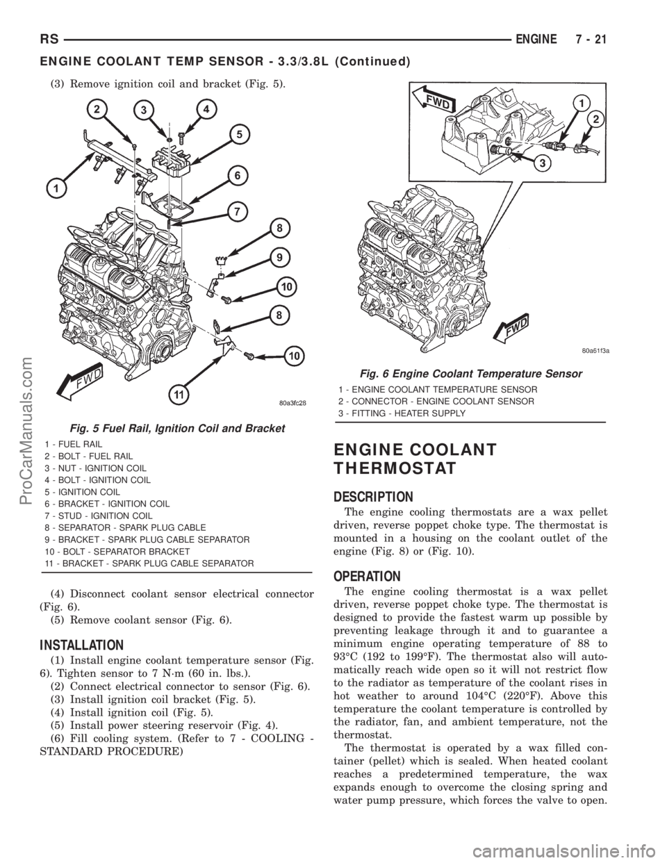
(3) Remove ignition coil and bracket (Fig. 5).
(4) Disconnect coolant sensor electrical connector
(Fig. 6).
(5) Remove coolant sensor (Fig. 6).
INSTALLATION
(1) Install engine coolant temperature sensor (Fig.
6). Tighten sensor to 7 N´m (60 in. lbs.).
(2) Connect electrical connector to sensor (Fig. 6).
(3) Install ignition coil bracket (Fig. 5).
(4) Install ignition coil (Fig. 5).
(5) Install power steering reservoir (Fig. 4).
(6) Fill cooling system. (Refer to 7 - COOLING -
STANDARD PROCEDURE)
ENGINE COOLANT
THERMOSTAT
DESCRIPTION
The engine cooling thermostats are a wax pellet
driven, reverse poppet choke type. The thermostat is
mounted in a housing on the coolant outlet of the
engine (Fig. 8) or (Fig. 10).
OPERATION
The engine cooling thermostat is a wax pellet
driven, reverse poppet choke type. The thermostat is
designed to provide the fastest warm up possible by
preventing leakage through it and to guarantee a
minimum engine operating temperature of 88 to
93ÉC (192 to 199ÉF). The thermostat also will auto-
matically reach wide open so it will not restrict flow
to the radiator as temperature of the coolant rises in
hot weather to around 104ÉC (220ÉF). Above this
temperature the coolant temperature is controlled by
the radiator, fan, and ambient temperature, not the
thermostat.
The thermostat is operated by a wax filled con-
tainer (pellet) which is sealed. When heated coolant
reaches a predetermined temperature, the wax
expands enough to overcome the closing spring and
water pump pressure, which forces the valve to open.
Fig. 5 Fuel Rail, Ignition Coil and Bracket
1 - FUEL RAIL
2 - BOLT - FUEL RAIL
3 - NUT - IGNITION COIL
4 - BOLT - IGNITION COIL
5 - IGNITION COIL
6 - BRACKET - IGNITION COIL
7 - STUD - IGNITION COIL
8 - SEPARATOR - SPARK PLUG CABLE
9 - BRACKET - SPARK PLUG CABLE SEPARATOR
10 - BOLT - SEPARATOR BRACKET
11 - BRACKET - SPARK PLUG CABLE SEPARATOR
Fig. 6 Engine Coolant Temperature Sensor
1 - ENGINE COOLANT TEMPERATURE SENSOR
2 - CONNECTOR - ENGINE COOLANT SENSOR
3 - FITTING - HEATER SUPPLY
RSENGINE7-21
ENGINE COOLANT TEMP SENSOR - 3.3/3.8L (Continued)
ProCarManuals.com
Page 296 of 2321
REMOVAL
There are no repairs to be made to the fan or
shroud assembly. If the fan is warped, cracked, or
otherwise damaged, it must be replaced as an assem-
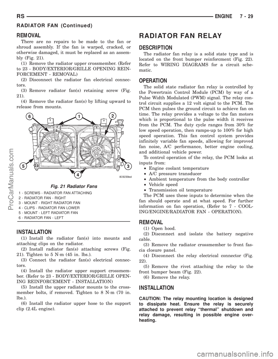
bly (Fig. 21).
(1) Remove the radiator upper crossmember. (Refer
to 23 - BODY/EXTERIOR/GRILLE OPENING REIN-
FORCEMENT - REMOVAL)
(2) Disconnect the radiator fan electrical connec-
tors.
(3) Remove radiator fan(s) retaining screw (Fig.
21).
(4) Remove the radiator fan(s) by lifting upward to
release from mounts.
INSTALLATION
(1) Install the radiator fan(s) into mounts and
attaching clips on the radiator.
(2) Install radiator fan(s) attaching screws (Fig.
21). Tighten to 5 N´m (45 in. lbs.).
(3) Connect the radiator fan(s) electrical connec-
tors.
(4) Install the radiator upper support crossmem-
ber. (Refer to 23 - BODY/EXTERIOR/GRILLE OPEN-
ING REINFORCEMENT - INSTALLATION)
(5) Install the upper radiator mounts to the cross-
member bolts, if removed. Tighten to 8 N´m (70 in.
lbs.).
(6) Install the radiator upper hose to the support
clip (2.4L engine).
RADIATOR FAN RELAY
DESCRIPTION
The radiator fan relay is a solid state type and is
located on the front bumper reinforcment (Fig. 22).
Refer to WIRING DIAGRAMS for a circuit sche-
matic.
OPERATION
The solid state radiator fan relay is controlled by
the Powertrain Control Module (PCM) by way of a
Pulse Width Modulated (PWM) signal. The relay con-
trol circuit supplies a 12 volt signal to the PCM. The
PCM then pulses the ground circuit to achieve fan on
time. The relay provides a voltage to the fan motors
which is proportional to the pulse width it receives
from the PCM. The duty cycle ranges from 30% for
low speed operation, then ramps-up to 100% for high
speed operation. This fan control system provides
infinitely variable fan speeds, allowing for improved
fan noise, A/C performance, better engine cooling,
and additional vehicle power.
To control operation of the relay, the PCM looks at
inputs from:
²Engine coolant temperature
²A/C pressure transducer
²Ambient temperature from the body controller
²Vehicle speed
²Transmission oil temperature
The PCM uses these inputs to determine when the
fan should operate and at what speed. For further
information on fan operation, (Refer to 7 - COOL-
ING/ENGINE/RADIATOR FAN - OPERATION).
REMOVAL
(1) Open hood.
(2) Disconnect and isolate the battery negative
cable.
(3) Remove the radiator crossmember to front fas-
cia closure panel.
(4) Disconnect the relay electrical connector (Fig.
22).
(5) Remove the rivet attaching the relay to the
front bumper beam (Fig. 22).
(6) Remove the relay.
INSTALLATION
CAUTION: The relay mounting location is designed
to dissipate heat. Ensure the relay is securely
attached to prevent relay ªthermalº shutdown and
relay damage, resulting in possible engine over-
heating.
Fig. 21 Radiator Fans
1 - SCREWS - RADIATOR FAN ATTACHING
2 - RADIATOR FAN - RIGHT
3 - MOUNT - RIGHT RADIATOR FAN
4 - CLIPS - RADIATOR FAN LOWER
5 - MOUNT - LEFT RADIATOR FAN
6 - RADIATOR FAN - LEFT
RSENGINE7-29
RADIATOR FAN (Continued)
ProCarManuals.com
Page 304 of 2321
- 31TH/OIL PUMP - STANDARD PROCEDURE)
(Refer to 21 - TRANSMISSION/TRANSAXLE/AU-
TOMATIC - 41TE/OIL PUMP - STANDARD PRO-
CEDURE)
(b) If oil pump volume is within specification, a
possible restriction in the cooler lines or cooler has
occurred.
(c) If oil pump volume is not within specification,
possible internal transmission restrictions, compo-
nent wear or damage has occurred. (Refer to 21 -
TRANSMISSION/TRANSAXLE/AUTOMATIC -
31TH - DIAGNOSIS AND TESTING) (Refer to 21 -
TRANSMISSION/TRANSAXLE/AUTOMATIC -
41TE - DIAGNOSIS AND TESTING)
(d) If an oil cooler restriction is suspected, per-
form further inspections and flow meter testing by
isolating components (i.e. lines, coolers).
(e) After a restriction is isolated, perform cooler
flush procedure. (Refer to 7 - COOLING/TRANS-
MISSION - STANDARD PROCEDURE)
(f) Re-test cooler flow. If cooler flow does not
exceed minimum specification, replace compo-
nent(s) as necessary.
STANDARD PROCEDURE - FLUSHING
COOLERS AND TUBES
The recommended procedure for cooler flushing is
to use Tool 6906 Cooler Flusher.
WARNING:
WEAR PROTECTIVE EYEWEAR THAT MEETS THE
REQUIREMENTS OF OSHA AND ANSI Z87.1±1968.
WEAR STANDARD INDUSTRIAL RUBBER GLOVES.
KEEP LIGHTED CIGARETTES, SPARKS, FLAMES,
AND OTHER IGNITION SOURCES AWAY FROM THE
AREA TO PREVENT THE IGNITION OF COMBUSTI-
BLE LIQUIDS AND GASES. KEEP A CLASS (B) FIRE
EXTINGUISHER IN THE AREA WHERE THE
FLUSHER WILL BE USED.
KEEP THE AREA WELL VENTILATED.
DO NOT LET FLUSHING SOLVENT COME IN CON-
TACT WITH YOUR EYES OR SKIN: IF EYE CONTAM-
INATION OCCURS, FLUSH EYES WITH WATER FOR15 TO 20 SECONDS. REMOVE CONTAMINATED
CLOTHING AND WASH AFFECTED SKIN WITH
SOAP AND WATER. SEEK MEDICAL ATTENTION.
(1) Remove cover plate filler plug on Tool 6906.
Fill reservoir 1/2 to 3/4 full of fresh flushing solution.
Use MopartTransmission Cooler Flush (MS-552) or
equivalent solution conforming to MS-552. Flushing
solvents are petroleum based solutions generally
used to clean automatic transmission components.
DO NOTuse solvents containing acids, water, gaso-
line, or any other corrosive liquids.
(2) Reinstall filler plug on Tool 6906.
(3) Verify pump power switch is turned OFF. Con-
nect red alligator clip to positive (+) battery post.
Connect black (-) alligator clip to a good ground.
NOTE: When flushing transmission cooler and
lines, ALWAYS reverse flush.
(4) Connect the BLUE pressure line to the OUT-
LET (From) cooler line.
(5) Connect the CLEAR return line to the INLET
(To) cooler line
(6) Turn pump ON for two to three minutes to
flush cooler and lines.
(7) Turn pump OFF.
(8) Disconnect CLEAR suction line from reservoir
at cover plate. Disconnect CLEAR return line at
cover plate, and place it in a drain pan.
(9) Turn pump ON for 30 seconds to purge flush-
ing solution from cooler and lines. Turn pump OFF.
(10) Place CLEAR suction line into a one quart
container of MopartATF+4 (Automatic Transmission
FluidÐType 9602).
(11) Turn pump ON until all transmission fluid is
removed from the one quart container and lines. This
purges any residual cleaning solvent from the trans-
mission cooler and lines. Turn pump OFF.
(12) Disconnect alligator clips from battery. Recon-
nect flusher lines to cover plate, and remove flushing
adapters from cooler lines.
RSTRANSMISSION7-37
TRANSMISSION (Continued)
ProCarManuals.com
Page 305 of 2321
TRANS COOLER
DESCRIPTION
The transmission oil cooler is an external oil-to-air
type cooler is mounted between the front of the radi-
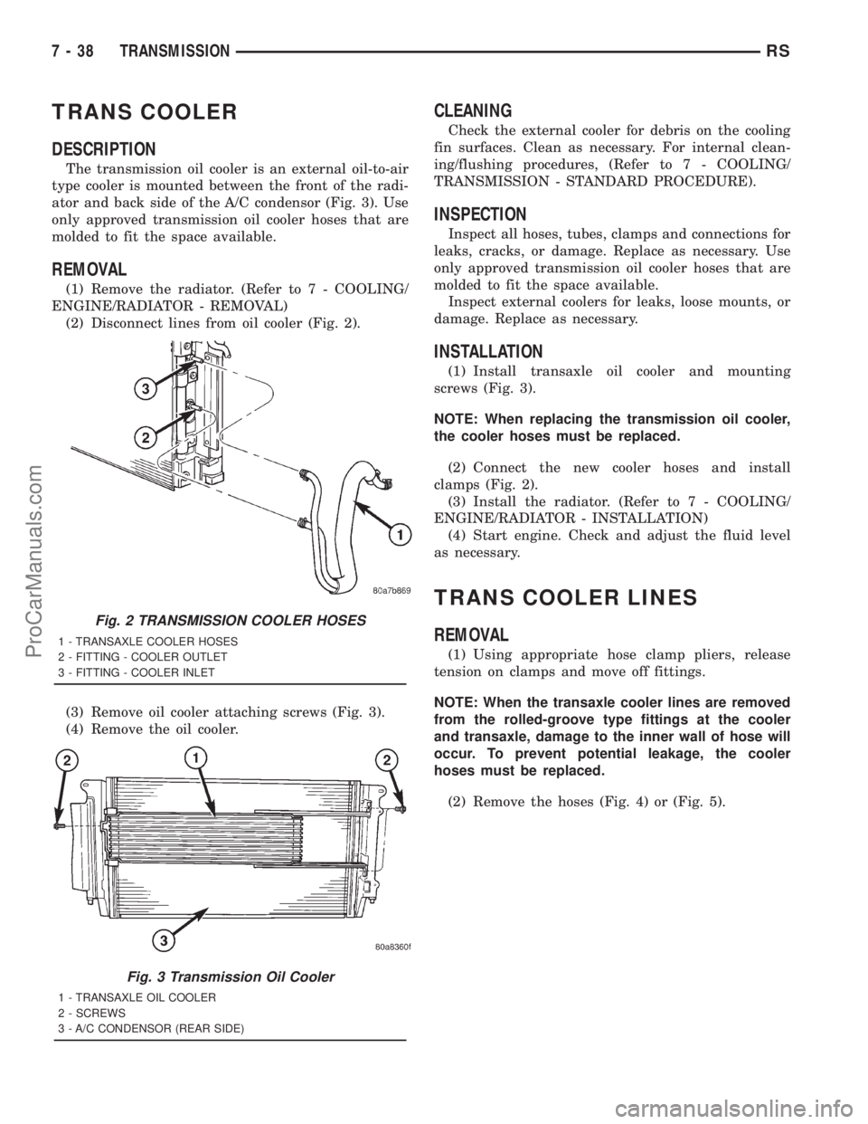
ator and back side of the A/C condensor (Fig. 3). Use
only approved transmission oil cooler hoses that are
molded to fit the space available.
REMOVAL
(1) Remove the radiator. (Refer to 7 - COOLING/
ENGINE/RADIATOR - REMOVAL)
(2) Disconnect lines from oil cooler (Fig. 2).
(3) Remove oil cooler attaching screws (Fig. 3).
(4) Remove the oil cooler.
CLEANING
Check the external cooler for debris on the cooling
fin surfaces. Clean as necessary. For internal clean-
ing/flushing procedures, (Refer to 7 - COOLING/
TRANSMISSION - STANDARD PROCEDURE).
INSPECTION
Inspect all hoses, tubes, clamps and connections for
leaks, cracks, or damage. Replace as necessary. Use
only approved transmission oil cooler hoses that are
molded to fit the space available.
Inspect external coolers for leaks, loose mounts, or
damage. Replace as necessary.
INSTALLATION
(1) Install transaxle oil cooler and mounting
screws (Fig. 3).
NOTE: When replacing the transmission oil cooler,
the cooler hoses must be replaced.
(2) Connect the new cooler hoses and install
clamps (Fig. 2).
(3) Install the radiator. (Refer to 7 - COOLING/
ENGINE/RADIATOR - INSTALLATION)
(4) Start engine. Check and adjust the fluid level
as necessary.
TRANS COOLER LINES
REMOVAL
(1) Using appropriate hose clamp pliers, release
tension on clamps and move off fittings.
NOTE: When the transaxle cooler lines are removed
from the rolled-groove type fittings at the cooler
and transaxle, damage to the inner wall of hose will
occur. To prevent potential leakage, the cooler
hoses must be replaced.
(2) Remove the hoses (Fig. 4) or (Fig. 5).
Fig. 2 TRANSMISSION COOLER HOSES
1 - TRANSAXLE COOLER HOSES
2 - FITTING - COOLER OUTLET
3 - FITTING - COOLER INLET
Fig. 3 Transmission Oil Cooler
1 - TRANSAXLE OIL COOLER
2 - SCREWS
3 - A/C CONDENSOR (REAR SIDE)
7 - 38 TRANSMISSIONRS
ProCarManuals.com
Page 306 of 2321
INSTALLATION
NOTE: When the transaxle cooler lines are removed
from the rolled-groove type fittings at the cooler
and transaxle, damage to the inner wall of hose willoccur. To prevent potential leakage, the cooler
hoses must be replaced.
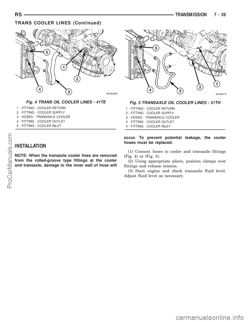
(1) Connect hoses to cooler and transaxle fittings
(Fig. 4) or (Fig. 5).
(2) Using appropriate pliers, position clamps over
fittings and release tension.
(3) Start engine and check transaxle fluid level.
Adjust fluid level as necessary.
Fig. 4 TRANS OIL COOLER LINES - 41TE
1 - FITTING - COOLER RETURN
2 - FITTING - COOLER SUPPLY
3 - HOSES - TRANSAXLE COOLER
4 - FITTING - COOLER OUTLET
5 - FITTING - COOLER INLET
Fig. 5 TRANSAXLE OIL COOLER LINES - 31TH
1 - FITTING - COOLER RETURN
2 - FITTING - COOLER SUPPLY
3 - HOSES - TRANSAXLE COOLER
4 - FITTING - COOLER OUTLET
5 - FITTING - COOLER INLET
RSTRANSMISSION7-39
TRANS COOLER LINES (Continued)
ProCarManuals.com
Page 322 of 2321
100 Percent Ethylene-GlycolÐShould Not Be Used in
Chrysler Vehicles
Use of 100 percent ethylene-glycol will cause for-
mation of additive deposits in the system, as the cor-
rosion inhibitive additives in ethylene-glycol require
the presence of water to dissolve. The deposits act as
insulation, causing temperatures to rise to as high as
149 deg. C (300 deg. F). This temperature is hot
enough to melt plastic and soften solder. The
increased temperature can result in engine detona-
tion. In addition, 100 percent ethylene-glycol freezes
at -22 deg. C (-8 deg. F ).
Propylene-glycol FormulationsÐShould Not Be Used in
Chrysler Vehicles
Propylene-glycol formulations do not meet
Chrysler coolant specifications.It's overall effec-
tive temperature range is smaller than that of ethyl-
ene-glycol. The freeze point of 50/50 propylene-glycol
and water is -32 deg. C (-26 deg. F). 5 deg. C higher
than ethylene-glycol's freeze point. The boiling point
(protection against summer boil-over) of propylene-
glycol is 125 deg. C (257 deg.F)at96.5 kPa (14 psi),
compared to 128 deg. C (263 deg. F) for ethylene-gly-
col. Use of propylene-glycol can result in boil-over or
freeze-up in Chrysler vehicles, which are designed for
ethylene-glycol. Propylene glycol also has poorer heat
transfer characteristics than ethylene glycol. This
can increase cylinder head temperatures under cer-
tain conditions.
Propylene-glycol/Ethylene-glycol MixturesÐShould Not Be
Used in Chrysler Vehicles
Propylene-glycol/ethylene-glycol Mixtures can
cause the destabilization of various corrosion inhibi-
tors, causing damage to the various cooling system
components. Also, once ethylene-glycol and propy-
lene-glycol based coolants are mixed in the vehicle,
conventional methods of determining freeze point will
not be accurate. Both the refractive index and spe-
cific gravity differ between ethylene glycol and propy-
lene glycol.
CAUTION: Richer antifreeze mixtures cannot be
measured with normal field equipment and can
cause problems associated with 100 percent ethyl-
ene-glycol.DIAGNOSIS AND TESTING - COOLANT
CONCENTRATION TESTING
Coolant concentration should be checked when any
additional coolant was added to system or after a
coolant drain, flush and refill. The coolant mixture
offers optimum engine cooling and protection against
corrosion when mixed to a freeze point of -37ÉC
(-34ÉF) to -59ÉC (-50ÉF). The use of a hydrometer or a
refractometer can be used to test coolant concentra-
tion.
A hydrometer will test the amount of glycol in a
mixture by measuring the specific gravity of the mix-
ture. The higher the concentration of ethylene glycol,
the larger the number of balls that will float, and
higher the freeze protection (up to a maximum of
60% by volume glycol).
A refractometer will test the amount of glycol in a
coolant mixture by measuring the amount a beam of
light bends as it passes through the fluid.
Some coolant manufactures use other types of gly-
cols into their coolant formulations. Propylene glycol
is the most common new coolant. However, propylene
glycol based coolants do not provide the same freez-
ing protection and corrosion protection and is not rec-
ommended.
CAUTION: Do not mix types of coolantÐcorrosion
protection will be severely reduced.
STANDARD PROCEDURE - COOLANT SERVICE
For engine coolant recommended service schedule,
(Refer to LUBRICATION & MAINTENANCE/MAIN-
TENANCE SCHEDULES - DESCRIPTION).
STANDARD PROCEDURE - ADDING
ADDITIONAL COOLANT
The pressure/vent cap should not be removed
from the coolant recovery pressure container.
When additional coolant is needed to maintain this
level, it should be added to the coolant recovery pres-
sure container (Fig. 1). Use only 50/50 mix of ethyl-
ene glycol type antifreeze and distilled water. For the
recommeded antifreeze/coolant type (Refer to LUBRI-
CATION & MAINTENANCE/FLUID TYPES -
DESCRIPTION).
CAUTION: Do not use well water, or suspect water
supply in cooling system. A 50/50 ethylene glycol
and distilled water mix is recommended. For the
recommeded antifreeze/coolant type (Refer to
LUBRICATION & MAINTENANCE/FLUID TYPES -
DESCRIPTION).
RGENGINE7a-15
COOLANT (Continued)
ProCarManuals.com
Page 335 of 2321

OPERATION - HOSE CLAMPS
The spring type hose clamp applies constant ten-
sion on a hose connection. To remove a spring type
hose clamp, use Special Tool 6094 or equivalent, con-
stant tension clamp pliers (Fig. 24) to compress the
hose clamp.
RADIATOR FAN RELAY
DESCRIPTION
The low and high speed fan relays are mounted to
the upper radiator support above the charge air
cooler (Fig. 25).
OPERATION
The cooling system uses two fans. Both fans oper-
ate at two different speeds, low and high. Depending
on engine coolant temperature and A/C system high
side pressure, the fans operate at either low or high.
The ignition switch supplies voltage to the coil side of
the relay. When the ECM grounds the coil side of the
relay, the contacts close and the battery supplies
power to the fans.
COOLANT SYSTEM HOSES
REMOVAL - UPPER RADIATOR HOSE
WARNING: THE WARNING WORDS ªDO NOT OPEN
HOTº ON THE RADIATOR PRESSURE CAP IS A
SAFETY PRECAUTION. WHEN HOT, PRESSURE
BUILDS UP IN COOLING SYSTEM. TO PREVENT
SCALDING OR INJURY, THE RADIATOR CAP
SHOULD NOT BE REMOVED WHILE THE SYSTEM
IS HOT OR UNDER PRESSURE.(1) Remove engine cover (Refer to 9 - ENGINE -
REMOVAL).
(2) Drain cooling system (Refer to 7 - COOLING/
ENGINE/COOLANT - STANDARD PROCEDURE).
(3) Remove upper radiator hose (Fig. 26).
REMOVAL - LOWER RADIATOR HOSE
WARNING: THE WARNING WORDS ªDO NOT OPEN
HOTº ON THE RADIATOR PRESSURE CAP IS A
SAFETY PRECAUTION. WHEN HOT, PRESSURE
BUILDS UP IN COOLING SYSTEM. TO PREVENT
SCALDING OR INJURY, THE RADIATOR CAP
SHOULD NOT BE REMOVED WHILE THE SYSTEM
IS HOT OR UNDER PRESSURE.
(1) Drain cooling system (Refer to 7 - COOLING/
ENGINE/COOLANT - STANDARD PROCEDURE).
(2) Remove lower radiator hose (Fig. 26).
REMOVAL - COOLANT BYPASS HOSE
WARNING: THE WARNING WORDS ªDO NOT OPEN
HOTº ON THE RADIATOR PRESSURE CAP IS A
SAFETY PRECAUTION. WHEN HOT, PRESSURE
BUILDS UP IN COOLING SYSTEM. TO PREVENT
SCALDING OR INJURY, THE RADIATOR CAP
SHOULD NOT BE REMOVED WHILE THE SYSTEM
IS HOT OR UNDER PRESSURE.
(1) Drain cooling system (Refer to 7 - COOLING/
ENGINE/COOLANT - STANDARD PROCEDURE).
(2) Remove the coolant bypass hose (Fig. 26).
Fig. 24 Hose Clamp Tool
1 - HOSE CLAMP TOOL 6094
2 - HOSE CLAMP
Fig. 25 RELAY LOCATIONS
1 - GLOW PLUG RELAY
2 - UPPER RADIATOR SUPPORT
3 - CHARGE AIR COOLER OUTLET HOSE
4 - RADIATOR FAN RELAYS
5 - UPPER RADIATOR HOSE
6 - EGR SOLENOID
7a - 28 ENGINERG
HOSE CLAMPS (Continued)
ProCarManuals.com
Page 410 of 2321

SPECIAL TOOLS
SPECIAL TOOLS
BATTERY TEMPERATURE
SENSOR
DESCRIPTION
The PCM incorporates a Battery Temperature Sen-
sor (BTS) on its circuit board.
OPERATION
The PCM uses the temperature of the battery area
to control the charge rate. This temperature data,
along with data from monitored line voltage, is used
by the PCM to vary the battery charging rate. The
system voltage is higher at cold temperatures and is
gradually reduced as temperature around the battery
increases.
The function of the battery temperature sensor
(BTS) is to enable control of the generator output
based upon ambient battery temperature. As battery
temperature increases, the charging rate should
decrease. As battery temperature decreases, the
charging rate should increase. The sensor functions
similar to the ECT sensor with one major difference,
the ambient sensor does not have a dual temperature
range program. The PCM maintains the optimal out-
put of the generator by monitoring battery voltage
and controlling battery voltage to a range of
13.5-14.7 volts based on battery temperature.
The battery temperature sensor is also used for
OBD II diagnostics. Certain faults and OBD II mon-
itors are either enabled or disabled depending upon
the battery temperature sensor input (example: dis-
able purge and EGR, enable LDP). Most OBD II
monitors are disabled below 20ÉF.
REMOVAL
The battery temperature sensor is not a serviced
separately. If replacement is necessary, the PCM
must be replaced.
GENERATOR
DESCRIPTION
The generator is belt-driven by the engine. It is
serviced only as a complete assembly. The generator
produces DC voltage at the B+ terminal. If the gen-
erator is failed, the generator assembly subcompo-
nents (generator and decoupler pulley) must be
inspected for individual failure and replaced accord-
ingly.
OPERATION
As the energized rotor begins to rotate within the
generator, the spinning magnetic field induces a cur-
rent into the windings of the stator coil. Once the
generator begins producing sufficient current, it also
provides the current needed to energize the rotor.
The Y type stator winding connections deliver the
induced AC current to 3 positive and 3 negative
diodes for rectification. From the diodes, rectified DC
current is delivered to the vehicles electrical system
through the generator, battery, and ground terminals.
Noise emitting from the generator may be caused
by:
²Worn, loose or defective bearings
²Loose or defective drive pulley (2.4L) or decou-
pler (3.3/3.8L)
²Incorrect, worn, damaged or misadjusted drive
belt
²Loose mounting bolts
²Misaligned drive pulley
²Defective stator or diode
²Damaged internal fins
REMOVAL - 2.4L
(1) Release hood latch and open hood.
(2) Disconnect battery negative cable.
(3) Disconnect the Inlet Air Temperature sensor.
(4) Remove the Air Box, refer to the Engine/Air
Cleaner for more information.
(5) Remove the EVAP Purge solenoid from its
bracket and reposition.
(6) Disconnect the push-in field wire connector
from back of generator.
(7) Remove nut holding B+ wire terminal to back
of generator.
(8) Separate B+ terminal from generator.
(9) Remove accessory drive belt, refer to the Cool-
ing System section for proper procedures.
(10) Remove the generator.
Fig. 1 GENERATOR DECOUPLER 8433
RSCHARGING8F-23
ProCarManuals.com