2001 DODGE TOWN AND COUNTRY sensor
[x] Cancel search: sensorPage 1700 of 2321
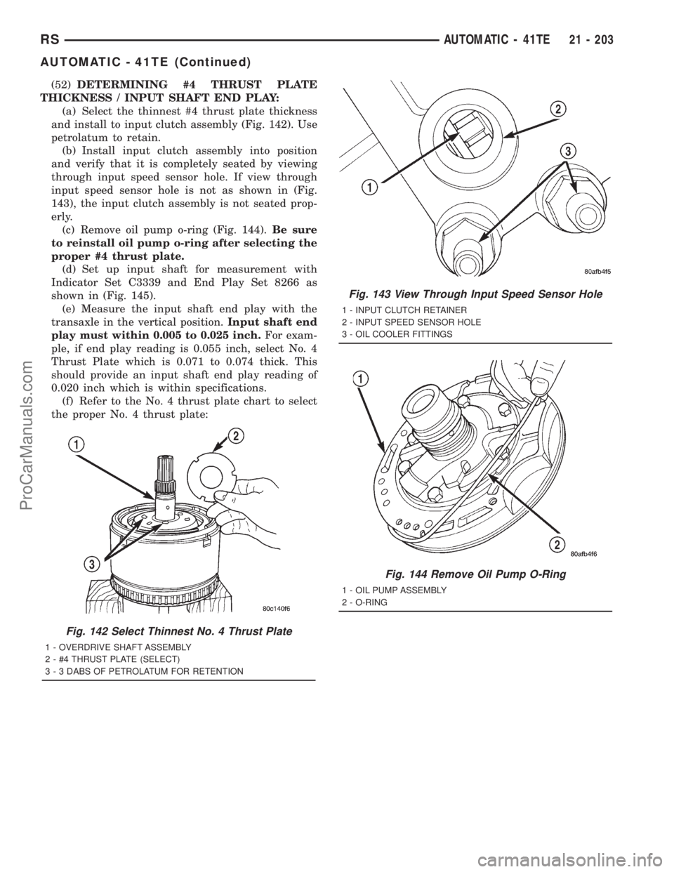
(52)DETERMINING #4 THRUST PLATE
THICKNESS / INPUT SHAFT END PLAY:
(a) Select the thinnest #4 thrust plate thickness
and install to input clutch assembly (Fig. 142). Use
petrolatum to retain.
(b) Install input clutch assembly into position
and verify that it is completely seated by viewing
through input speed sensor hole. If view through
input speed sensor hole is not as shown in (Fig.
143), the input clutch assembly is not seated prop-
erly.
(c) Remove oil pump o-ring (Fig. 144).Be sure
to reinstall oil pump o-ring after selecting the
proper #4 thrust plate.
(d) Set up input shaft for measurement with
Indicator Set C3339 and End Play Set 8266 as
shown in (Fig. 145).
(e) Measure the input shaft end play with the
transaxle in the vertical position.Input shaft end
play must within 0.005 to 0.025 inch.For exam-
ple, if end play reading is 0.055 inch, select No. 4
Thrust Plate which is 0.071 to 0.074 thick. This
should provide an input shaft end play reading of
0.020 inch which is within specifications.
(f) Refer to the No. 4 thrust plate chart to select
the proper No. 4 thrust plate:
Fig. 142 Select Thinnest No. 4 Thrust Plate
1 - OVERDRIVE SHAFT ASSEMBLY
2 - #4 THRUST PLATE (SELECT)
3 - 3 DABS OF PETROLATUM FOR RETENTION
Fig. 143 View Through Input Speed Sensor Hole
1 - INPUT CLUTCH RETAINER
2 - INPUT SPEED SENSOR HOLE
3 - OIL COOLER FITTINGS
Fig. 144 Remove Oil Pump O-Ring
1 - OIL PUMP ASSEMBLY
2 - O-RING
RSAUTOMATIC - 41TE21 - 203
AUTOMATIC - 41TE (Continued)
ProCarManuals.com
Page 1705 of 2321
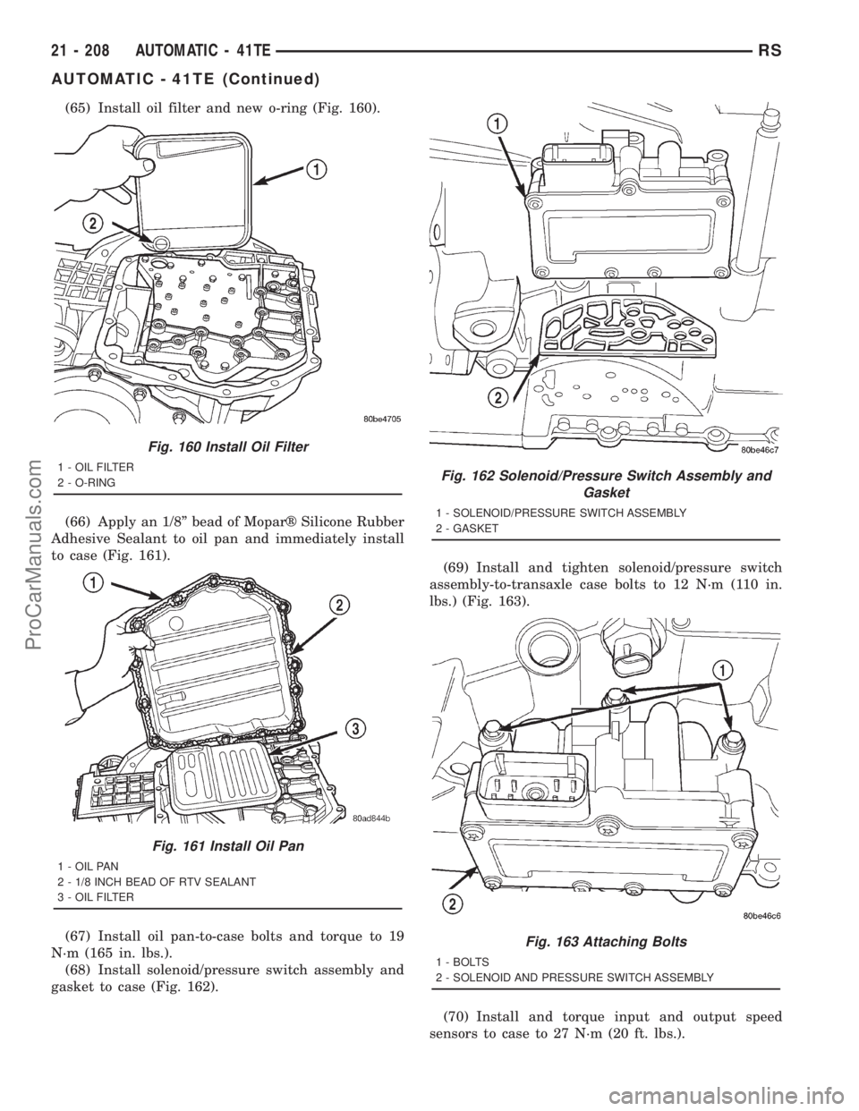
(65) Install oil filter and new o-ring (Fig. 160).
(66) Apply an 1/8º bead of Moparž Silicone Rubber
Adhesive Sealant to oil pan and immediately install
to case (Fig. 161).
(67) Install oil pan-to-case bolts and torque to 19
N´m (165 in. lbs.).
(68) Install solenoid/pressure switch assembly and
gasket to case (Fig. 162).(69) Install and tighten solenoid/pressure switch
assembly-to-transaxle case bolts to 12 N´m (110 in.
lbs.) (Fig. 163).
(70) Install and torque input and output speed
sensors to case to 27 N´m (20 ft. lbs.).
Fig. 160 Install Oil Filter
1 - OIL FILTER
2 - O-RING
Fig. 161 Install Oil Pan
1 - OIL PAN
2 - 1/8 INCH BEAD OF RTV SEALANT
3 - OIL FILTER
Fig. 162 Solenoid/Pressure Switch Assembly and
Gasket
1 - SOLENOID/PRESSURE SWITCH ASSEMBLY
2 - GASKET
Fig. 163 Attaching Bolts
1 - BOLTS
2 - SOLENOID AND PRESSURE SWITCH ASSEMBLY
21 - 208 AUTOMATIC - 41TERS
AUTOMATIC - 41TE (Continued)
ProCarManuals.com
Page 1706 of 2321
INSTALLATION
NOTE: If transaxle assembly has been replaced or
overhauled (clutch and/or seal replacement), it is
necessary to perfrom the TCM Quick Learn proce-
dure. (Refer to 8 - ELECTRICAL/ELECTRONIC CON-
TROL MODULES/TRANSMISSION CONTROL
MODULE - STANDARD PROCEDURE)
NOTE: If torque converter assembly has been
replaced, it is necessary to reset the TCC Break-In
Strategy. (Refer to 8 - ELECTRICAL/ELECTRONIC
CONTROL MODULES/TRANSMISSION CONTROL
MODULE - STANDARD PROCEDURE)
(1) Using a transmission jack and a helper, posi-
tion transaxle assembly to engine. Install and torque
bolts to 95 N´m (70 ft. lbs.).
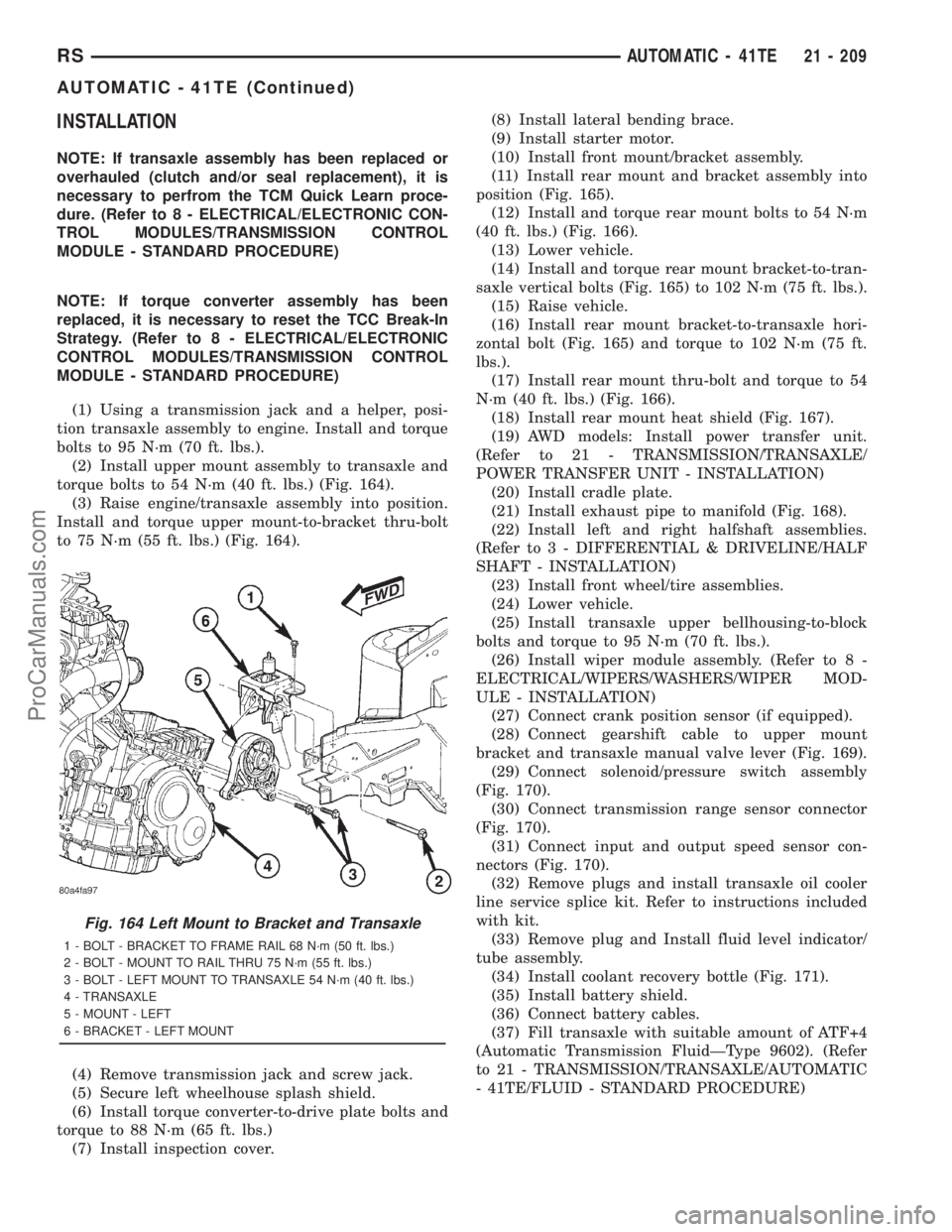
(2) Install upper mount assembly to transaxle and
torque bolts to 54 N´m (40 ft. lbs.) (Fig. 164).
(3) Raise engine/transaxle assembly into position.
Install and torque upper mount-to-bracket thru-bolt
to 75 N´m (55 ft. lbs.) (Fig. 164).
(4) Remove transmission jack and screw jack.
(5) Secure left wheelhouse splash shield.
(6) Install torque converter-to-drive plate bolts and
torque to 88 N´m (65 ft. lbs.)
(7) Install inspection cover.(8) Install lateral bending brace.
(9) Install starter motor.
(10) Install front mount/bracket assembly.
(11) Install rear mount and bracket assembly into
position (Fig. 165).
(12) Install and torque rear mount bolts to 54 N´m
(40 ft. lbs.) (Fig. 166).
(13) Lower vehicle.
(14) Install and torque rear mount bracket-to-tran-
saxle vertical bolts (Fig. 165) to 102 N´m (75 ft. lbs.).
(15) Raise vehicle.
(16) Install rear mount bracket-to-transaxle hori-
zontal bolt (Fig. 165) and torque to 102 N´m (75 ft.
lbs.).
(17) Install rear mount thru-bolt and torque to 54
N´m (40 ft. lbs.) (Fig. 166).
(18) Install rear mount heat shield (Fig. 167).
(19) AWD models: Install power transfer unit.
(Refer to 21 - TRANSMISSION/TRANSAXLE/
POWER TRANSFER UNIT - INSTALLATION)
(20) Install cradle plate.
(21) Install exhaust pipe to manifold (Fig. 168).
(22) Install left and right halfshaft assemblies.
(Refer to 3 - DIFFERENTIAL & DRIVELINE/HALF
SHAFT - INSTALLATION)
(23) Install front wheel/tire assemblies.
(24) Lower vehicle.
(25) Install transaxle upper bellhousing-to-block
bolts and torque to 95 N´m (70 ft. lbs.).
(26) Install wiper module assembly. (Refer to 8 -
ELECTRICAL/WIPERS/WASHERS/WIPER MOD-
ULE - INSTALLATION)
(27) Connect crank position sensor (if equipped).
(28) Connect gearshift cable to upper mount
bracket and transaxle manual valve lever (Fig. 169).
(29) Connect solenoid/pressure switch assembly
(Fig. 170).
(30) Connect transmission range sensor connector
(Fig. 170).
(31) Connect input and output speed sensor con-
nectors (Fig. 170).
(32) Remove plugs and install transaxle oil cooler
line service splice kit. Refer to instructions included
with kit.
(33) Remove plug and Install fluid level indicator/
tube assembly.
(34) Install coolant recovery bottle (Fig. 171).
(35) Install battery shield.
(36) Connect battery cables.
(37) Fill transaxle with suitable amount of ATF+4
(Automatic Transmission FluidÐType 9602). (Refer
to 21 - TRANSMISSION/TRANSAXLE/AUTOMATIC
- 41TE/FLUID - STANDARD PROCEDURE)
Fig. 164 Left Mount to Bracket and Transaxle
1 - BOLT - BRACKET TO FRAME RAIL 68 N´m (50 ft. lbs.)
2 - BOLT - MOUNT TO RAIL THRU 75 N´m (55 ft. lbs.)
3 - BOLT - LEFT MOUNT TO TRANSAXLE 54 N´m (40 ft. lbs.)
4 - TRANSAXLE
5 - MOUNT - LEFT
6 - BRACKET - LEFT MOUNT
RSAUTOMATIC - 41TE21 - 209
AUTOMATIC - 41TE (Continued)
ProCarManuals.com
Page 1708 of 2321
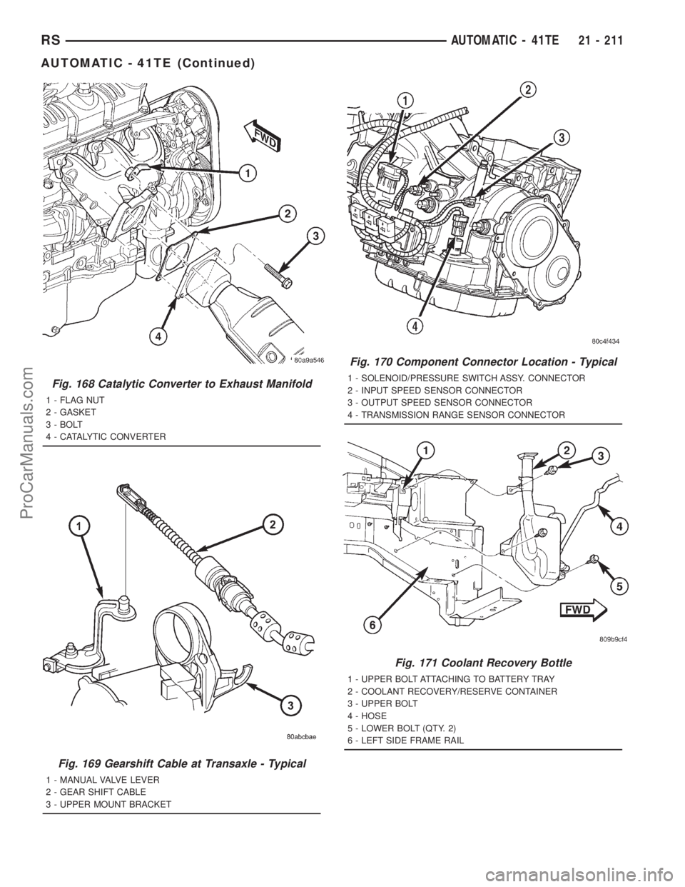
Fig. 168 Catalytic Converter to Exhaust Manifold
1 - FLAG NUT
2 - GASKET
3 - BOLT
4 - CATALYTIC CONVERTER
Fig. 169 Gearshift Cable at Transaxle - Typical
1 - MANUAL VALVE LEVER
2 - GEAR SHIFT CABLE
3 - UPPER MOUNT BRACKET
Fig. 170 Component Connector Location - Typical
1 - SOLENOID/PRESSURE SWITCH ASSY. CONNECTOR
2 - INPUT SPEED SENSOR CONNECTOR
3 - OUTPUT SPEED SENSOR CONNECTOR
4 - TRANSMISSION RANGE SENSOR CONNECTOR
Fig. 171 Coolant Recovery Bottle
1 - UPPER BOLT ATTACHING TO BATTERY TRAY
2 - COOLANT RECOVERY/RESERVE CONTAINER
3 - UPPER BOLT
4 - HOSE
5 - LOWER BOLT (QTY. 2)
6 - LEFT SIDE FRAME RAIL
RSAUTOMATIC - 41TE21 - 211
AUTOMATIC - 41TE (Continued)
ProCarManuals.com
Page 1723 of 2321
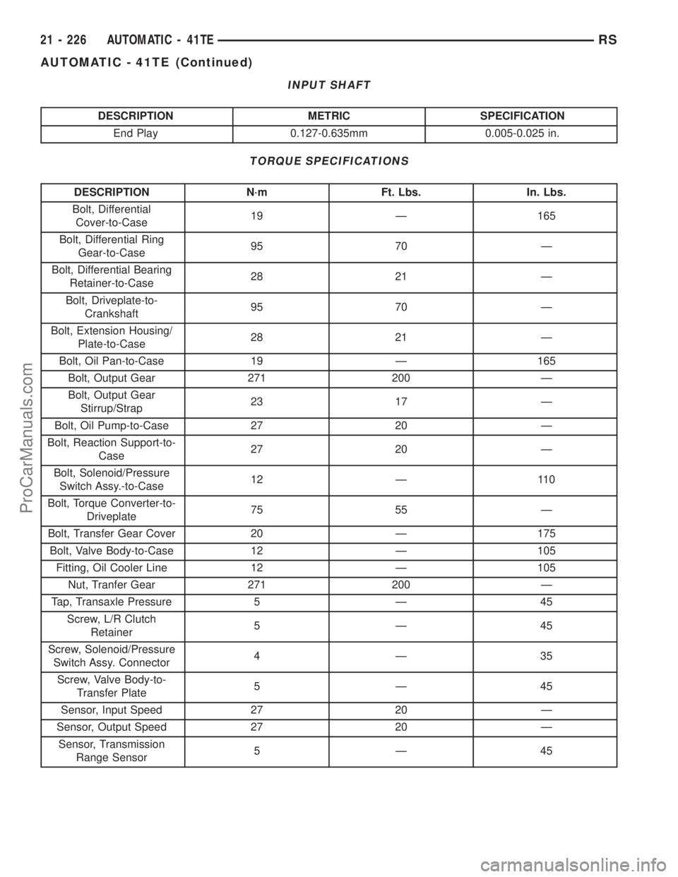
INPUT SHAFT
DESCRIPTION METRIC SPECIFICATION
End Play 0.127-0.635mm 0.005-0.025 in.
TORQUE SPECIFICATIONS
DESCRIPTION N´m Ft. Lbs. In. Lbs.
Bolt, Differential
Cover-to-Case19 Ð 165
Bolt, Differential Ring
Gear-to-Case95 70 Ð
Bolt, Differential Bearing
Retainer-to-Case28 21 Ð
Bolt, Driveplate-to-
Crankshaft95 70 Ð
Bolt, Extension Housing/
Plate-to-Case28 21 Ð
Bolt, Oil Pan-to-Case 19 Ð 165
Bolt, Output Gear 271 200 Ð
Bolt, Output Gear
Stirrup/Strap23 17 Ð
Bolt, Oil Pump-to-Case 27 20 Ð
Bolt, Reaction Support-to-
Case27 20 Ð
Bolt, Solenoid/Pressure
Switch Assy.-to-Case12 Ð 110
Bolt, Torque Converter-to-
Driveplate75 55 Ð
Bolt, Transfer Gear Cover 20 Ð 175
Bolt, Valve Body-to-Case 12 Ð 105
Fitting, Oil Cooler Line 12 Ð 105
Nut, Tranfer Gear 271 200 Ð
Tap, Transaxle Pressure 5 Ð 45
Screw, L/R Clutch
Retainer5Ð45
Screw, Solenoid/Pressure
Switch Assy. Connector4Ð35
Screw, Valve Body-to-
Transfer Plate5Ð45
Sensor, Input Speed 27 20 Ð
Sensor, Output Speed 27 20 Ð
Sensor, Transmission
Range Sensor5Ð45
21 - 226 AUTOMATIC - 41TERS
AUTOMATIC - 41TE (Continued)
ProCarManuals.com
Page 1743 of 2321
FLUID
STANDARD PROCEDURE - FLUID LEVEL AND
CONDITION CHECK
NOTE: Only transmission fluid of the type labeled
Mopar ATF+4 (Automatic Transmission Fluid±Type
9602) should be used in this transaxle.
FLUID LEVEL CHECK
The transmission sump has a fluid level indicator
(dipstick) to check oil similar to most automatic
transmissions. It is located on the left side of the
engine. Be sure to wipe all dirt from dipstick handle
before removing.
The torque converter fills in both the P Park and N
Neutral positions. Place the selector lever in P Park
to be sure that the fluid level check is accurate.The
engine should be running at idle speed for at
least one minute, with the vehicle on level
ground.At normal operating temperature (approxi-
mately 82 C. or 180 F.), the fluid level is correct if it
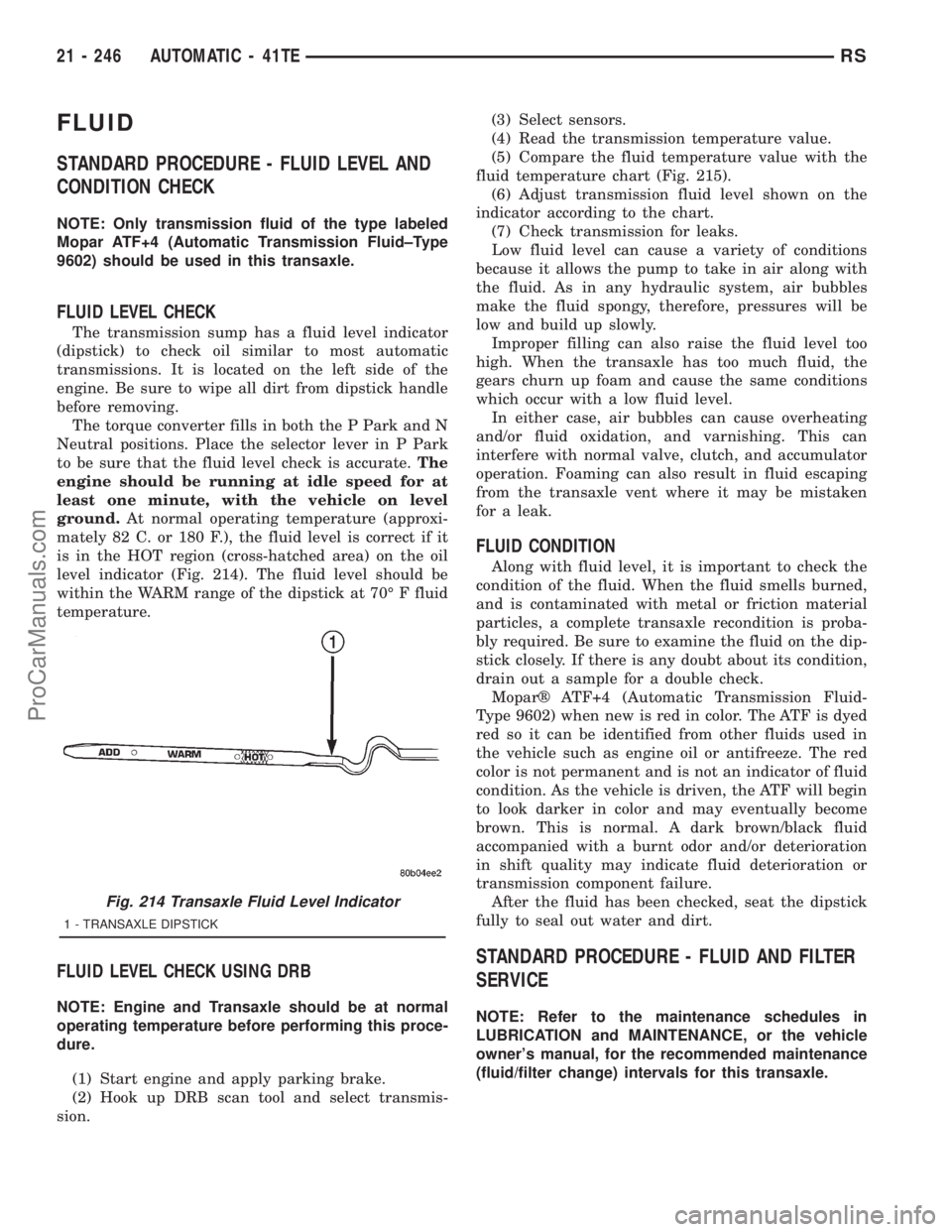
is in the HOT region (cross-hatched area) on the oil
level indicator (Fig. 214). The fluid level should be
within the WARM range of the dipstick at 70É F fluid
temperature.
FLUID LEVEL CHECK USING DRB
NOTE: Engine and Transaxle should be at normal
operating temperature before performing this proce-
dure.
(1) Start engine and apply parking brake.
(2) Hook up DRB scan tool and select transmis-
sion.(3) Select sensors.
(4) Read the transmission temperature value.
(5) Compare the fluid temperature value with the
fluid temperature chart (Fig. 215).
(6) Adjust transmission fluid level shown on the
indicator according to the chart.
(7) Check transmission for leaks.
Low fluid level can cause a variety of conditions
because it allows the pump to take in air along with
the fluid. As in any hydraulic system, air bubbles
make the fluid spongy, therefore, pressures will be
low and build up slowly.
Improper filling can also raise the fluid level too
high. When the transaxle has too much fluid, the
gears churn up foam and cause the same conditions
which occur with a low fluid level.
In either case, air bubbles can cause overheating
and/or fluid oxidation, and varnishing. This can
interfere with normal valve, clutch, and accumulator
operation. Foaming can also result in fluid escaping
from the transaxle vent where it may be mistaken
for a leak.
FLUID CONDITION
Along with fluid level, it is important to check the
condition of the fluid. When the fluid smells burned,
and is contaminated with metal or friction material
particles, a complete transaxle recondition is proba-
bly required. Be sure to examine the fluid on the dip-
stick closely. If there is any doubt about its condition,
drain out a sample for a double check.
Moparž ATF+4 (Automatic Transmission Fluid-
Type 9602) when new is red in color. The ATF is dyed
red so it can be identified from other fluids used in
the vehicle such as engine oil or antifreeze. The red
color is not permanent and is not an indicator of fluid
condition. As the vehicle is driven, the ATF will begin
to look darker in color and may eventually become
brown. This is normal. A dark brown/black fluid
accompanied with a burnt odor and/or deterioration
in shift quality may indicate fluid deterioration or
transmission component failure.
After the fluid has been checked, seat the dipstick
fully to seal out water and dirt.
STANDARD PROCEDURE - FLUID AND FILTER
SERVICE
NOTE: Refer to the maintenance schedules in
LUBRICATION and MAINTENANCE, or the vehicle
owner's manual, for the recommended maintenance
(fluid/filter change) intervals for this transaxle.
Fig. 214 Transaxle Fluid Level Indicator
1 - TRANSAXLE DIPSTICK
21 - 246 AUTOMATIC - 41TERS
ProCarManuals.com
Page 1774 of 2321
ing state. The result is an apply or release of a fric-
tional element.
The 2/4 and UD solenoids are normally applied,
which by design allow fluid to pass through in their
relaxed or ªoffº state. This allows transaxle limp-in
(P,R,N,2) in the event of an electrical failure.
The continuity of the solenoids and circuits are
periodically tested. Each solenoid is turned on or off
depending on its current state. An inductive spike
should be detected by the TCM during this test. It no
spike is detected, the circuit is tested again to verify
the failure. In addition to the periodic testing, the
solenoid circuits are tested if a speed ratio or pres-
sure switch error occurs.
PRESSURE SWITCHES
The TCM relies on three pressure switches to mon-
itor fluid pressure in the L/R, 2/4, and OD hydraulic
circuits. The primary purpose of these switches is to
help the TCM detect when clutch circuit hydraulic
failures occur. The range for the pressure switch clos-
ing and opening points is 11-23 psi. Typically the
switch opening point will be approximately one psi
lower than the closing point. For example, a switch
may close at 18 psi and open at 17 psi. The switches
are continuously monitored by the TCM for the cor-
rect states (open or closed) in each gear as shown in
the following chart:
PRESSURE SWITCH STATES
GEAR L/R 2/4 OD
ROPOPOP
P/N CL OP OP
1st CL OP OP
2nd OP CL OP
DOPOPCL
OD OP CL CL
OP = OPEN
CL = CLOSED
A Diagnostic Trouble Code (DTC) will set if the
TCM senses any switch open or closed at the wrong
time in a given gear.
The TCM also tests the 2/4 and OD pressure
switches when they are normally off (OD and 2/4 are
tested in 1st gear, OD in 2nd gear, and 2/4 in 3rd
gear). The test simply verifies that they are opera-
tional, by looking for a closed state when the corre-
sponding element is applied. Immediately after a
shift into 1st, 2nd, or 3rd gear with the engine speed
above 1000 rpm, the TCM momentarily turns on ele-
ment pressure to the 2/4 and/or OD clutch circuits to
identify that the appropriate switch has closed. If it
doesn't close, it is tested again. If the switch fails toclose the second time, the appropriate Diagnostic
Trouble Code (DTC) will set.
REMOVAL
NOTE: If solenoid/pressure switch assembly is
being replaced, it is necessary to perform the TCM
Quick Learn Procedure. (Refer to 8 - ELECTRICAL/
ELECTRONIC CONTROL MODULES/TRANSMISSION
CONTROL MODULE - STANDARD PROCEDURE)
(1) Disconnect battery negative cable.
(2) Remove air cleaner assembly.
(3) Disconnect solenoid/pressure switch assembly
connector.
(4) Disconnect input speed sensor connector.
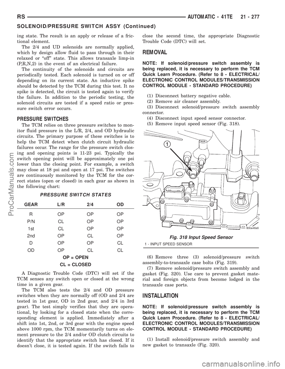
(5) Remove input speed sensor (Fig. 318).
(6) Remove three (3) solenoid/pressure switch
assembly-to-transaxle case bolts (Fig. 319).
(7) Remove solenoid/pressure switch assembly and
gasket (Fig. 320). Use care to prevent gasket mate-
rial and foreign objects from become lodged in the
transaxle case ports.
INSTALLATION
NOTE: If solenoid/pressure switch assembly is
being replaced, it is necessary to perform the TCM
Quick Learn Procedure. (Refer to 8 - ELECTRICAL/
ELECTRONIC CONTROL MODULES/TRANSMISSION
CONTROL MODULE - STANDARD PROCEDURE)
(1) Install solenoid/pressure switch assembly and
new gasket to transaxle (Fig. 320).
Fig. 318 Input Speed Sensor
1 - INPUT SPEED SENSOR
RSAUTOMATIC - 41TE21 - 277
SOLENOID/PRESSURE SWITCH ASSY (Continued)
ProCarManuals.com
Page 1775 of 2321
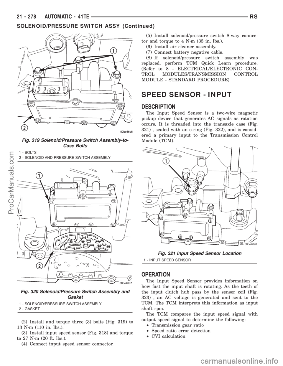
(2) Install and torque three (3) bolts (Fig. 319) to
13 N´m (110 in. lbs.).
(3) Install input speed sensor (Fig. 318) and torque
to 27 N´m (20 ft. lbs.).
(4) Connect input speed sensor connector.(5) Install solenoid/pressure switch 8-way connec-
tor and torque to 4 N´m (35 in. lbs.).
(6) Install air cleaner assembly.
(7) Connect battery negative cable.
(8) If solenoid/pressure switch assembly was
replaced, perform TCM Quick Learn procedure.
(Refer to 8 - ELECTRICAL/ELECTRONIC CON-
TROL MODULES/TRANSMISSION CONTROL
MODULE - STANDARD PROCEDURE)
SPEED SENSOR - INPUT
DESCRIPTION
The Input Speed Sensor is a two-wire magnetic
pickup device that generates AC signals as rotation
occurs. It is threaded into the transaxle case (Fig.
321) , sealed with an o-ring (Fig. 322), and is consid-
ered a primary input to the Transmission Control
Module (TCM).
OPERATION
The Input Speed Sensor provides information on
how fast the input shaft is rotating. As the teeth of
the input clutch hub pass by the sensor coil (Fig.
323) , an AC voltage is generated and sent to the
TCM. The TCM interprets this information as input
shaft rpm.
The TCM compares the input speed signal with
output speed signal to determine the following:
²Transmission gear ratio
²Speed ratio error detection
²CVI calculation
Fig. 319 Solenoid/Pressure Switch Assembly-to-
Case Bolts
1 - BOLTS
2 - SOLENOID AND PRESSURE SWITCH ASSEMBLY
Fig. 320 Solenoid/Pressure Switch Assembly and
Gasket
1 - SOLENOID/PRESSURE SWITCH ASSEMBLY
2 - GASKET
Fig. 321 Input Speed Sensor Location
1 - INPUT SPEED SENSOR
21 - 278 AUTOMATIC - 41TERS
SOLENOID/PRESSURE SWITCH ASSY (Continued)
ProCarManuals.com