2001 DODGE TOWN AND COUNTRY steering
[x] Cancel search: steeringPage 1896 of 2321
TIRES/WHEELS
TABLE OF CONTENTS
page page
TIRES/WHEELS
DIAGNOSIS AND TESTING..................1
TIRE AND WHEEL VIBRATION..............1
STANDARD PROCEDURE...................4
TIRE AND WHEEL BALANCE...............4
TIRE AND WHEEL MATCH MOUNTING.......6
TIRE AND WHEEL ROTATION..............6
REMOVAL...............................7
INSTALLATION............................7
TIRES
DESCRIPTION............................8
DIAGNOSIS AND TESTING..................9
TIRE NOISE............................9
TIRE/VEHICLE LEAD.....................9
TIRE WEAR PATTERNS..................11
TREAD WEAR INDICATORS...............11
STANDARD PROCEDURE..................11
TIRE INFLATION PRESSURES.............11
TIRE PRESSURE FOR HIGH SPEED
OPERATION...........................12TIRE LEAK REPAIRING..................12
CLEANING..............................13
WHEELS
DESCRIPTION...........................13
DIAGNOSIS AND TESTING.................13
WHEEL INSPECTION....................13
CLEANING..............................14
SPECIFICATIONS........................14
WHEEL COVER
DESCRIPTION...........................14
REMOVAL..............................14
INSTALLATION...........................14
WHEEL MOUNTING STUDS - FRONT
REMOVAL..............................15
INSTALLATION...........................16
WHEEL MOUNTING STUDS - REAR
REMOVAL..............................16
INSTALLATION...........................17
TIRES/WHEELS
DIAGNOSIS AND TESTING - TIRE AND WHEEL
VIBRATION
Tire and wheel imbalance, runout and force varia-
tion can cause vehicles to exhibit steering wheel
vibration.
VISUAL INSPECTION
Visual inspection of the vehicle is recommended
prior to road testing or performing any other proce-
dure. Raise vehicle on a suitable hoist. Refer to
Hoisting in Lubrication and Maintenance.
Inspect for the following:
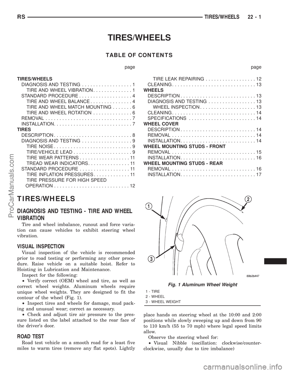
²Verify correct (OEM) wheel and tire, as well as
correct wheel weights. Aluminum wheels require
unique wheel weights. They are designed to fit the
contour of the wheel (Fig. 1).
²Inspect tires and wheels for damage, mud pack-
ing and unusual wear; correct as necessary.
²Check and adjust tire air pressure to the pres-
sure listed on the label attached to the rear face of
the driver's door.
ROAD TEST
Road test vehicle on a smooth road for a least five
miles to warm tires (remove any flat spots). Lightlyplace hands on steering wheel at the 10:00 and 2:00
positions while slowly sweeping up and down from 90
to 110 km/h (55 to 70 mph) where legal speed limits
allow.
Observe the steering wheel for:
²Visual Nibble (oscillation: clockwise/counter-
clockwise, usually due to tire imbalance)
Fig. 1 Aluminum Wheel Weight
1 - TIRE
2 - WHEEL
3 - WHEEL WEIGHT
RSTIRES/WHEELS22-1
ProCarManuals.com
Page 1904 of 2321
Performance tires will have a speed rating letter
after the aspect ratio number. For example, the letter
ªSº indicates that the tire is speed rated up to 112
mph (180 km/h). The speed rating is not always
printed on the tire sidewall.
²Q -up to 100 mph (160 km/h)
²S -up to 112 mph (180 km/h)
²T -up to 118 mph (190 km/h)
²U -up to 124 mph (200 km/h)
²H -up to 130 mph (210 km/h)
²V -up to 149 mph (240 km/h)
²Z -more than 149 mph (240 km/h) (consult the
tire manufacturer for the specific speed rating)
An All Season type tire will have eitherM+S,M
& S or M-S (indicating mud and snow traction)
imprinted on the side wall.
TIRE CHAINS
Refer to the owners manual supplied with the vehi-
cle to determine whether the use of tire chains is per-
mitted on this vehicle.
DESCRIPTION - RADIAL-PLY TIRES
Radial-ply tires improve handling, tread life, ride
quality and decrease rolling resistance.
Radial-ply tires must always be used in sets of four
and under no circumstances should they be used on
the front only. It is recommended that tires from dif-
ferent manufacturers NOT be mixed. They may bemixed with a temporary spare tire when necessary. A
maximum speed of 80 km/h (50 mph) is recom-
mended while a temporary spare is in use.
Radial-ply tires have the same load-carrying capac-
ity as other types of tires of the same size. They also
use the same recommended inflation pressures.
DESCRIPTION - REPLACEMENT TIRES
WARNING: FAILURE TO EQUIP THE VEHICLE WITH
TIRES HAVING ADEQUATE SPEED CAPABILITY
CAN RESULT IN SUDDEN TIRE FAILURE.
It is recommended that tires equivalent to the orig-
inal equipment tires be used when replacement is
needed.
Failure to use equivalent replacement tires may
adversely affect the safety and handling of the vehicle.
The original equipment tires provide a proper com-
bination of many characteristics such as:
²Ride
²Noise
²Handling
²Durability
²Tread life
²Traction
²Rolling resistance
²Speed capability
The use of oversize tires may cause interference
with vehicle components. Under extremes of suspen-
sion and steering travel, interference with vehicle
components may cause tire damage.
DESCRIPTION - SPARE TIRE (TEMPORARY)
The temporary (convenience) spare tire is designed
for emergency use only. The original tire should be
repaired and reinstalled, or replaced with a new, at
the first opportunity.
The temporary (convenience) spare tire should be
inflated to the pressure listed on its sidewall. Do not
exceed speeds of 80 km/h (50 mph) when the tempo-
rary spare tire is in use on the vehicle. Refer to the
Owner's Manual for more details.
DIAGNOSIS AND TESTING - TIRE NOISE
Unusual tire noise can be associated with tire and
wheel vibration or irregular tire wear. For vibration,
(Refer to 22 - TIRES/WHEELS - DIAGNOSIS AND
TESTING). For irregular tire wear, (Refer to 22 - TIRES/
WHEELS/TIRES - DIAGNOSIS AND TESTING).
DIAGNOSIS AND TESTING - TIRE/VEHICLE
LEAD
Use the following Vehicle Lead Diagnosis And Cor-
rection Chart to diagnose and correct a vehicle lead
or drift problem.
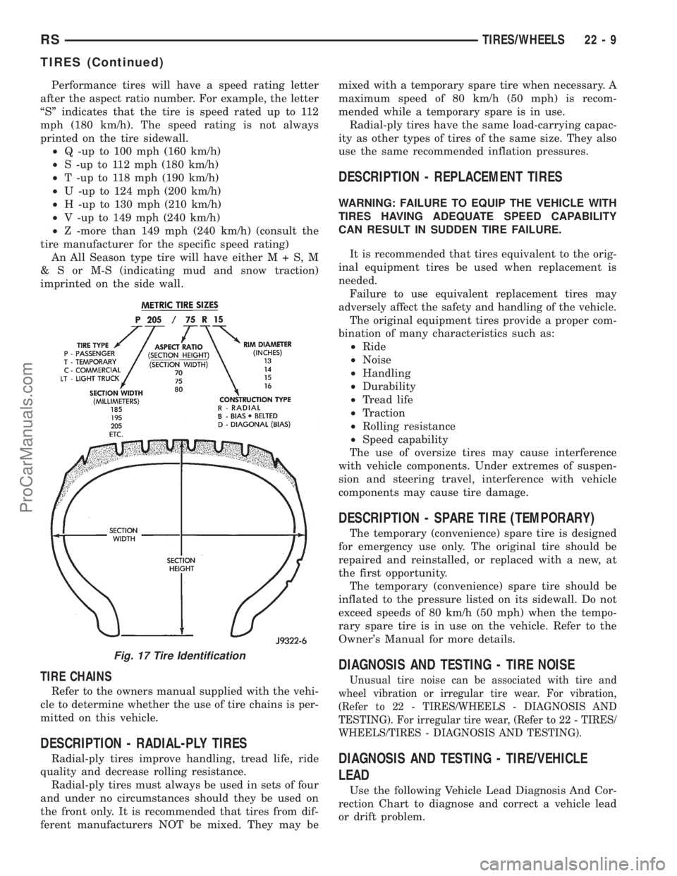
Fig. 17 Tire Identification
RSTIRES/WHEELS22-9
TIRES (Continued)
ProCarManuals.com
Page 1910 of 2321
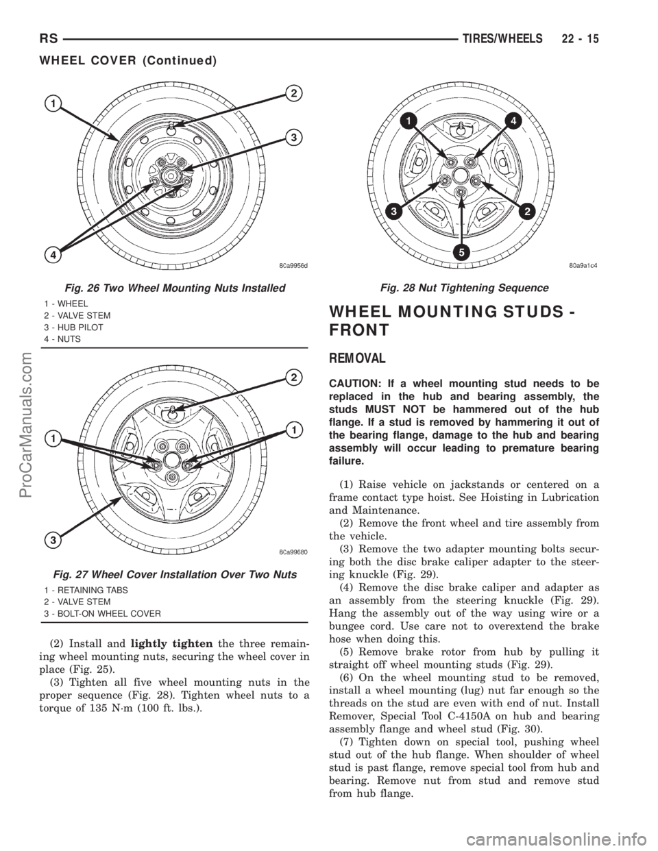
(2) Install andlightly tightenthe three remain-
ing wheel mounting nuts, securing the wheel cover in
place (Fig. 25).
(3) Tighten all five wheel mounting nuts in the
proper sequence (Fig. 28). Tighten wheel nuts to a
torque of 135 N´m (100 ft. lbs.).
WHEEL MOUNTING STUDS -
FRONT
REMOVAL
CAUTION: If a wheel mounting stud needs to be
replaced in the hub and bearing assembly, the
studs MUST NOT be hammered out of the hub
flange. If a stud is removed by hammering it out of
the bearing flange, damage to the hub and bearing
assembly will occur leading to premature bearing
failure.
(1) Raise vehicle on jackstands or centered on a
frame contact type hoist. See Hoisting in Lubrication
and Maintenance.
(2) Remove the front wheel and tire assembly from
the vehicle.
(3) Remove the two adapter mounting bolts secur-
ing both the disc brake caliper adapter to the steer-
ing knuckle (Fig. 29).
(4) Remove the disc brake caliper and adapter as
an assembly from the steering knuckle (Fig. 29).
Hang the assembly out of the way using wire or a
bungee cord. Use care not to overextend the brake
hose when doing this.
(5) Remove brake rotor from hub by pulling it
straight off wheel mounting studs (Fig. 29).
(6) On the wheel mounting stud to be removed,
install a wheel mounting (lug) nut far enough so the
threads on the stud are even with end of nut. Install
Remover, Special Tool C-4150A on hub and bearing
assembly flange and wheel stud (Fig. 30).
(7) Tighten down on special tool, pushing wheel
stud out of the hub flange. When shoulder of wheel
stud is past flange, remove special tool from hub and
bearing. Remove nut from stud and remove stud
from hub flange.
Fig. 26 Two Wheel Mounting Nuts Installed
1 - WHEEL
2 - VALVE STEM
3 - HUB PILOT
4 - NUTS
Fig. 27 Wheel Cover Installation Over Two Nuts
1 - RETAINING TABS
2 - VALVE STEM
3 - BOLT-ON WHEEL COVER
Fig. 28 Nut Tightening Sequence
RSTIRES/WHEELS22-15
WHEEL COVER (Continued)
ProCarManuals.com
Page 1911 of 2321
INSTALLATION
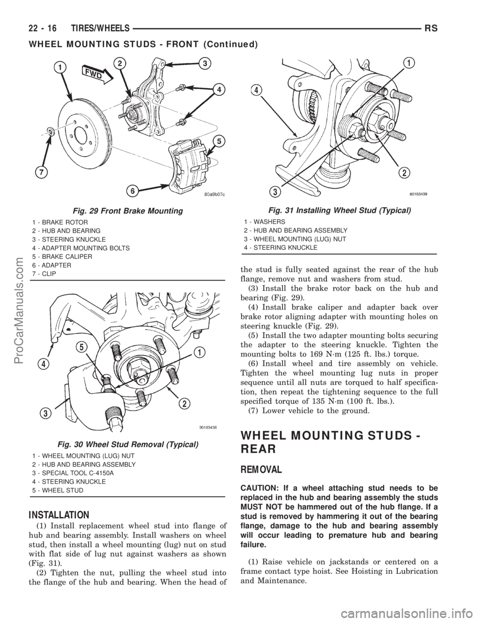
(1) Install replacement wheel stud into flange of
hub and bearing assembly. Install washers on wheel
stud, then install a wheel mounting (lug) nut on stud
with flat side of lug nut against washers as shown
(Fig. 31).
(2) Tighten the nut, pulling the wheel stud into
the flange of the hub and bearing. When the head ofthe stud is fully seated against the rear of the hub
flange, remove nut and washers from stud.
(3) Install the brake rotor back on the hub and
bearing (Fig. 29).
(4) Install brake caliper and adapter back over
brake rotor aligning adapter with mounting holes on
steering knuckle (Fig. 29).
(5) Install the two adapter mounting bolts securing
the adapter to the steering knuckle. Tighten the
mounting bolts to 169 N´m (125 ft. lbs.) torque.
(6) Install wheel and tire assembly on vehicle.
Tighten the wheel mounting lug nuts in proper
sequence until all nuts are torqued to half specifica-
tion, then repeat the tightening sequence to the full
specified torque of 135 N´m (100 ft. lbs.).
(7) Lower vehicle to the ground.
WHEEL MOUNTING STUDS -
REAR
REMOVAL
CAUTION: If a wheel attaching stud needs to be
replaced in the hub and bearing assembly the studs
MUST NOT be hammered out of the hub flange. If a
stud is removed by hammering it out of the bearing
flange, damage to the hub and bearing assembly
will occur leading to premature hub and bearing
failure.
(1) Raise vehicle on jackstands or centered on a
frame contact type hoist. See Hoisting in Lubrication
and Maintenance.
Fig. 29 Front Brake Mounting
1 - BRAKE ROTOR
2 - HUB AND BEARING
3 - STEERING KNUCKLE
4 - ADAPTER MOUNTING BOLTS
5 - BRAKE CALIPER
6 - ADAPTER
7 - CLIP
Fig. 30 Wheel Stud Removal (Typical)
1 - WHEEL MOUNTING (LUG) NUT
2 - HUB AND BEARING ASSEMBLY
3 - SPECIAL TOOL C-4150A
4 - STEERING KNUCKLE
5 - WHEEL STUD
Fig. 31 Installing Wheel Stud (Typical)
1 - WASHERS
2 - HUB AND BEARING ASSEMBLY
3 - WHEEL MOUNTING (LUG) NUT
4 - STEERING KNUCKLE
22 - 16 TIRES/WHEELSRS
WHEEL MOUNTING STUDS - FRONT (Continued)
ProCarManuals.com
Page 2115 of 2321
INSTRUMENT PANEL
TABLE OF CONTENTS
page page
CLUSTER BEZEL
REMOVAL.............................202
INSTALLATION..........................202
CUP HOLDER
REMOVAL.............................202
INSTALLATION..........................202
GLOVE BOX
REMOVAL.............................203
INSTALLATION..........................203
GLOVE BOX LATCH
REMOVAL.............................203
INSTALLATION..........................203
GLOVE BOX LATCH STRIKER
REMOVAL.............................203
INSTALLATION..........................203
INSTRUMENT PANEL ASSEMBLY
REMOVAL.............................203
INSTALLATION..........................204
INSTRUMENT PANEL CENTER BEZEL
REMOVAL.............................205
INSTALLATION..........................205INSTRUMENT PANEL END COVER
REMOVAL.............................205
INSTALLATION..........................205
INSTRUMENT PANEL TOP COVER
REMOVAL.............................205
INSTALLATION..........................206
KNEE BLOCKER REINFORCEMENT
REMOVAL.............................206
INSTALLATION..........................206
LOWER CONSOLE
REMOVAL.............................206
INSTALLATION..........................206
LOWER INSTRUMENT PANEL
REMOVAL.............................206
INSTALLATION..........................206
LOWER STEERING COLUMN COVER
REMOVAL.............................206
INSTALLATION..........................206
OVER STEERING COLUMN COVER
REMOVAL.............................207
INSTALLATION..........................207
CLUSTER BEZEL
REMOVAL
(1) Disconnect and isolate the battery negative
cable.
(2) Remove Over Steering Column Bezel by lifting
it straight up with a firm pull.
(3) Remove the four bezel attaching screws.
(4) Tilt the steering column in the full down posi-
tion.
(5) Pull rearward on the cluster bezel and remove.
INSTALLATION
(1) Manuever cluster bezel over steering column
and into position.
(2) Install the four bezel attaching screws.
(3) Install the Over Steering Column Bezel by
positioning it over the retaining slots and firmly
snapping it into place.
(4) Connect the battery negative cable.
CUP HOLDER
REMOVAL
(1) Remove the cup holder. Pull the cup holder out
and depress the tang in the middle back and pull
rearward to release the cup holder.
(2) Remove the screw access cover from the bottom
of the center bezel.
(3) Using a trim stick (special tool #C-4755) or
equivalent, gently pry out on the edge of the instru-
ment panel center bezel. Hang off to the side leaving
the accessory switches connected.
(4) Remove the cup holder assembly attaching
screws and pull the assembly rearward to disengage
the rear guide studs from instrument panel.
(5) Remove the cup holder track assembly.
INSTALLATION
(1) Install the cup holder track assembly.
(2) Place the cup holder track assembly into posi-
tion and slide into opening in instrument panel until
the rear guide struts snap into place. Install the cup
holder assembly attaching screws.
(3) Install the center bezel.
(4) Install the screw access cover from the bottom
of the center bezel.
23 - 202 INSTRUMENT PANELRS
ProCarManuals.com
Page 2116 of 2321
(5) Install the cup holder. Align the cup holder
assembly with the track and firmly slide shut to
engage retaining tang.
GLOVE BOX
REMOVAL
(1) Open glove box.
(2) Push in on sides of glove box bin and lower
door.
(3) Pivot glove box downward and disengage hinge
hooks from instrument panel.
(4) Remove glove box.
INSTALLATION
(1) Place glove box in position.
(2) Engage hinge hooks into instrument panel and
pivot glove box upward.
(3) Push in sides of glove box bin and snap glove
box assembly into instrument panel.
(4) Close glove box door.
GLOVE BOX LATCH
REMOVAL
(1) Open glove box.
(2) Push in on sides of glove box bin and lower
door.
(3) Pivot glove box downward and disengage hinge
hooks from instrument panel.
(4) Remove glove box.
(5) Remove the assembly screws.
(6) Disassemble the glove box.
(7) Separate the latch from the glove box assembly.
INSTALLATION
(1) Install the latch onto the glove box assembly.
(2) Assemble the glove box.
(3) Install the assembly screws.
(4) Engage hinge hooks into instrument panel and
pivot glove box upward.
(5) Push in sides of glove box bin and snap glove
box assembly into instrument panel.
(6) Close glove box door.
GLOVE BOX LATCH STRIKER
REMOVAL
(1) Open glove box door.
(2) Remove screws holding lock striker to instru-
ment panel.
(3) Remove glove box latch striker.
INSTALLATION
(1) Install the glove box latch striker.
(2) Install the screws holding latch striker to
instrument panel.
(3) Close glove box door.
INSTRUMENT PANEL
ASSEMBLY
REMOVAL
(1) Disconnect and isolate the battery negative
cable.
(2) Remove the lower console:
(a) Remove six retaining screws.
(b) Pull rearward and disconnect the auxiliary
power outlet.
(c) Remove lower console from vehicle.
(3) Remove the bolts holding the lower supports to
the instrument panel frame.
(4) Remove the bolts holding the lower supports to
the floor pan.
(5) Disconnect the wire connectors from the Pas-
senger Airbag.
(6) Remove the two screws to each right and left
cowl trim covers.
(7) Remove the both left and right side A-pillar
trim covers using a trim stick (special tool #C-4755)
or equivalent gently pry out on the trim covers and
remove.
(8) Remove the glove box:
(a) Push in on sides of glove box bin and lower
door.
(b) Pivot glove box downward and disengage
hinge hooks from instrument panel.
(c) Remove glove box from vehicle.
(9) Disconnect the antenna lead connector from
behind the glove box.
(10) Remove the four screws to the lower steering
column cover.
(11) Remove the eight screws to the plastic knee
blocker reinforcement.
(12) Unclip the Data Link Connector (DLC) from
the instrument panel reinforcement.
(13) Remove one screw to the left side instrument
panel silencer and remove.
(14) Disconnect the left side wiring:
(a) Brake switch.
(b) Main bulkhead connector.
(c) Five harness connectors.
(d) Driver airbag connector.
(15) Remove the two screws to the hood release
handle.
(16) Remove five screws to the left under column
instrument panel reinforcement brace and remove.
RSINSTRUMENT PANEL23 - 203
CUP HOLDER (Continued)
ProCarManuals.com
Page 2117 of 2321
(17) Remove the two steering column shroud
retaining screws. Separate the shrouds and remove
from vehicle.
(18) Disconnect the steering column wiring. There
are seven connectors and then unclip the harness
from the column.
(19) Disconnect the ORC harness connector.
(20) Remove the four nuts retaining the steering
column and lower to the floor.
(21) Remove the four nuts attaching the instru-
ment panel to the brake pedal support bracket.
(22) Loosen the left side roll down bolt.
(23) Remove the left side A-pillar retaining bolts.
There are two 13 mm bolts and one 10 mm bolt.
(24) If equipped with a mechanical transmission
range indicator:
(a) Remove the indicator cable loop.
(b) Remove the clip holding gear shift cable end
to the gear selector adapter.
(c) Pull the cable end from gear selector.
(d) Disconnect the clip for the indicator cable
and guide tube from the shift cable bracket and
move out of the way.
(25) Remove the instrument panel top cover. Using
a trim stick or equivalent, gently pry up on the front
edge of the top cover, pull rearward and remove from
vehicle.
(26) Disconnect the right side wire connectors from
the HVAC behind the glove box area and the two
antenna connectors behind the glove box hinge.
(27) Remove the right end cover by pulling out-
board.
(28) Remove the right side A-pillar retaining bolts.
There are two 13 mm bolts and one 10 mm bolt.
(29) Loosen the right side roll down bolt.
(30) Disconnect the two front window defroster
grid wire connectors. One on each side of vehicle.
(31) Remove both the left and right power mirrors:
(a) Using a trim stick or equivalent, gently pry
out on mirror trim cover.
(b) Open door and remove the three torx retain-
ing screws.
(c) Disconnect the wire connector and remove
mirror from the vehicle.
(32) Feed power mirror wire harness inboard
through the A-pillar.
(33) Remove the bolts holding the instrument
panel frame to the dash panel below windshield
opening.
(34) With the help of an assistant remove the
instrument panel from vehicle. Lift the instrument
panel up off the HVAC so you won't damage the seal-
ing surface of the distribution duct.
If the instrument panel is being replaced, transfer
all parts to the new instrument panel assembly.INSTALLATION
(1) With the help of an assistant place the instru-
ment panel into vehicle on roll down bolts. As you
roll the instrument panel up, lift the instrument
panel up so the duct work does not bind or bend and
you can set it down on the HVAC housing to get the
proper seal at the distribution duct. Get one bolt
started in the dash panel.
(2) Install the bolts holding the instrument panel
frame to the dash panel below windshield opening.
(3) Feed power mirror wire harness outboard
through the A-pillar.
(4) Install both the left and right power mirrors:
(a) Connect the wire connector and install the
mirror onto the vehicle.
(b) Install the three torx retaining screws.
(c) Using a firm push, snap the mirror trim
cover into place.
(5) Connect the two front window defroster grid
wire connectors. One on each side of vehicle.
(6) Tighten the right side roll down bolt.
(7) Install the right side A-pillar retaining bolts.
There are two 13 mm bolts and one 10 mm bolt.
(8) Install the right end cover. Position over retain-
ing slots and firmly snap into place.
(9) Connect the right side wire connectors to the
HVAC behind the glove box area and the two
antenna connectors behind the glove box hinge.
(10) Install the instrument panel top cover. Slide
the front edge of the top cover toward dash panel,
and firmly snap down the rear edge of the to cover to
engage clips.
(11) If equipped with a mechanical transmission
range indicator:
(a) Connect the clip for the indicator cable and
guide tube to the shift cable bracket.
(b) Install the cable end to the gear selector.
(c) Install the clip holding the gear shift cable
end to the gear selector adapter.
(d) Install the indicator cable loop.
(12) Install the left side A-pillar retaining bolts.
There are two 13 mm bolts and one 10 mm bolt.
(13) Tighten the left side roll down bolt.
(14) Install the four nuts attaching the instrument
panel to the brake pedal support bracket.
(15) Install the four nuts retaining the steering
column and lower to the floor.
(16) Connect the ORC harness connector.
(17) Connect the steering column wiring. There
are seven connectors and then clip the harness to the
column.
(18) Connect the shrouds and install the two steer-
ing column shroud retaining screws.
(19) Install five screws to the left under column
instrument panel reinforcement brace.
23 - 204 INSTRUMENT PANELRS
INSTRUMENT PANEL ASSEMBLY (Continued)
ProCarManuals.com
Page 2118 of 2321
(20) Install the two screws to the hood release
handle.
(21) Connect the left side wiring:
(a) Brake switch.
(b) Main bulkhead connector.
(c) Five harness connectors.
(d) Driver airbag connector.
(22) Install one screw to the left side instrument
panel silencer.
(23) Clip the Data Link Connector (DLC) to the
instrument panel reinforcement.
(24) Install the eight screws to the plastic knee
blocker reinforcement.
(25) Install the four screws to the lower steering
column cover.
(26) Install the glove box:
(a) Install glove box into the vehicle. Line up the
hinges and firmly snap together.
(b) Push in on sides of glove box bin and raise
door.
(27) Install the both left and right side A-pillar
trim covers. Position trim cover over slots and firmly
snap into place.
(28) Install the two screws to each right and left
cowl trim covers.
(29) Connect the wire connectors to the Passenger
Airbag.
(30) Install the bolts holding the lower supports to
the floor pan.
(31) Install the bolts holding the lower supports to
the instrument panel frame.
(32) Install the lower console:
(a) Install lower console to vehicle.
(b) Connect the auxiliary power outlet.
(c) Install the six retaining screws.
(33) Connect the battery negative cable.
INSTRUMENT PANEL CENTER
BEZEL
REMOVAL
(1) Disconnect and isolate the battery negative
cable.
(2) Remove cup holder. Refer to Body, Instrument
Panel, Cup Holder, Removal.
(3) Insert the trim stick (special tool #C-4755) or
equivalent between access cover and center bezel.
(4) Carefully pry the access cover from the instru-
ment panel.
(5) Remove the cup holder track. Refer to Body,
Instrument Panel, Cup Holder, Removal.
(6) Using a trim stick or equivalent, gently pry out
on the edge of the instrument panel center bezel and
pull outward.(7) Disconnect the wire connectors to the accessory
switches and HVAC control.
(8) Remove the instrument panel center bezel from
the vehicle.
INSTALLATION
(1) Install the instrument panel center bezel from
the vehicle.
(2) Connect the wire connectors to the accessory
switches and HVAC control.
(3) Position the center bezel over the retaining
slots and firmly snap the instrument panel center
bezel into place.
(4) Install the cup holder track. Refer to Body,
Instrument Panel, Cup Holder, Installation.
(5) Position the center bezel over the retaining
slots and firmly snap into place.
(6) Install cup holder. Refer to Body, Instrument
Panel, Cup Holder, Installation.
(7) Connect the battery negative cable.
INSTRUMENT PANEL END
COVER
REMOVAL
(1) Open passenger side front door.
(2) Place fingers in end cover grille, and with a
firm outboard pulling motion, disengage clips holding
end cover to instrument panel.
INSTALLATION
(1) Position end cover over retaining slots and
firmly snap into place.
(2) Close passenger side front door.
INSTRUMENT PANEL TOP
COVER
REMOVAL
(1) Remove A-pillar trim. Using a trim stick (spe-
cial tool #C-4755) or equivalent, gently pry out and
remove.
(2) Using a trim stick, disengage clips holding rear
edge of top cover to instrument panel.
NOTE: The Instrument Panel Top Cover may be
hard to unsnap from the instrument panel. Be sure
not to mar, scuff, or damage the instrument panel
pad.
(3) Pull top cover rearward to disengage hooks
holding front of top cover to instrument panel.
(4) Remove top cover from vehicle.
RSINSTRUMENT PANEL23 - 205
INSTRUMENT PANEL ASSEMBLY (Continued)
ProCarManuals.com