2001 DODGE TOWN AND COUNTRY air conditioning
[x] Cancel search: air conditioningPage 292 of 2321
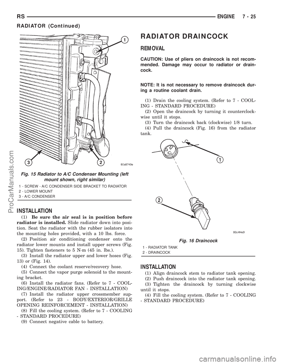
INSTALLATION
(1)Be sure the air seal is in position before
radiator is installed.Slide radiator down into posi-
tion. Seat the radiator with the rubber isolators into
the mounting holes provided, with a 10 lbs. force.
(2) Position air conditioning condenser onto the
radiator lower mounts and install upper screws (Fig.
15). Tighten fasteners to 5 N´m (45 in. lbs.).
(3) Install the radiator upper and lower hoses (Fig.
13) or (Fig. 14).
(4) Connect the coolant reserve/recovery hose.
(5) Connect the vapor purge solenoid to the mount-
ing bracket.
(6) Install the radiator fans. (Refer to 7 - COOL-
ING/ENGINE/RADIATOR FAN - INSTALLATION)
(7) Install the radiator upper crossmember sup-
port. (Refer to 23 - BODY/EXTERIOR/GRILLE
OPENING REINFORCEMENT - INSTALLATION)
(8) Fill the cooling system. (Refer to 7 - COOLING
- STANDARD PROCEDURE)
(9) Connect negative cable to battery.
RADIATOR DRAINCOCK
REMOVAL
CAUTION: Use of pliers on draincock is not recom-
mended. Damage may occur to radiator or drain-
cock.
NOTE: It is not necessary to remove draincock dur-
ing a routine coolant drain.
(1) Drain the cooling system. (Refer to 7 - COOL-
ING - STANDARD PROCEDURE)
(2) Open the draincock by turning it counterclock-
wise until it stops.
(3) Turn the draincock back (clockwise) 1/8 turn.
(4) Pull the draincock (Fig. 16) from the radiator
tank.
INSTALLATION
(1) Align draincock stem to radiator tank opening.
(2) Push draincock into the radiator tank opening.
(3) Tighten the draincock by turning clockwise
until it stops.
(4) Fill the cooling system. (Refer to 7 - COOLING
- STANDARD PROCEDURE)
Fig. 15 Radiator to A/C Condenser Mounting (left
mount shown, right similar)
1 - SCREW - A/C CONDENSER SIDE BRACKET TO RADIATOR
2 - LOWER MOUNT
3 - A/C CONDENSER
Fig. 16 Draincock
1 - RADIATOR TANK
2 - DRAINCOCK
RSENGINE7-25
RADIATOR (Continued)
ProCarManuals.com
Page 309 of 2321
COOLING SYSTEM DIAGNOSIS-DIESEL ENGINE
CONDITION POSSIBLE CAUSES CORRECTION
TEMPERATURE GAUGE
READS LOW1. Diesel engines, due to their
inherent effiency are slower to warm
up than gasoline powered engines,
and will operate at lower
temperatures when the vehicle is
unloaded.1. The low gauge reading may
be normal. Refer to thermostats
in the manual text for
information. See Thermostat
Diagnosis-Diesel Engine.
2. Is the temperature gauge
connected to the temperature gauge
coolant sensor on the engine?2. Check, the engine
temperature sensor connector
in the engine compartment.
3. Is the temperature gauge
operating OK?3. Check gauge operation.
Repair as necessary.
4. Coolant level low in cold ambient
temperatures accompanied with poor
heater performance.4. Check coolant level in the
coolant tank. Inspect system for
leaks. Repair leaks as
necessary. Refer to the Coolant
section for WARNINGS and
precautions before removing
the pressure cap.
5. Improper operation of internal
heater doors or heater controls.5. Inspect heater and repair as
necessary. Refer to Heating
and Air Conditioning for
procedures.
TEMPERATURE GAUGE
READS HIGH. COOLANT
MAY OR MAY NOT BE
LOST OR LEAKING FROM
COOLING SYSTEM1. Trailer is being towed, a steep hill
is being climbed, vehicle is operated
in slow moving traffic, or engine is
being idled with very high ambient
(outside) temperature and the air
conditioning is on. Higher altitudes
could aggravate these conditions.1. This may be a temporary
condition and repair is not
necessary. Turn off the air
conditioning and attempt to
drive the vehicle without any of
the previous conditions.
Observe the temperature
gauge. The gauge should return
to the normal range. If the
gauge does not return to
normal range, determine the
cause for the overheating and
repair.
2. Temperature gauge reading
incorrectly.2. Check gauge. Refer to I/P
group.
3. Coolant low in coolant tank and
radiator.3. Check for coolant leaks and
repair as necessary.
4. Pressure cap not installed tightly.
If cap is loose, boiling point of
coolant will be lowered.4. Tighten cap.
5. Poor seals at pressure/vent cap. 5. (a) Check condition of cap
and cap seals. (b) Check
condition of coolant tank filler
neck. Make sure it does not
leak pressure.
7a - 2 COOLING 2.5L TURBO DIESELRG
COOLING 2.5L TURBO DIESEL (Continued)
ProCarManuals.com
Page 328 of 2321
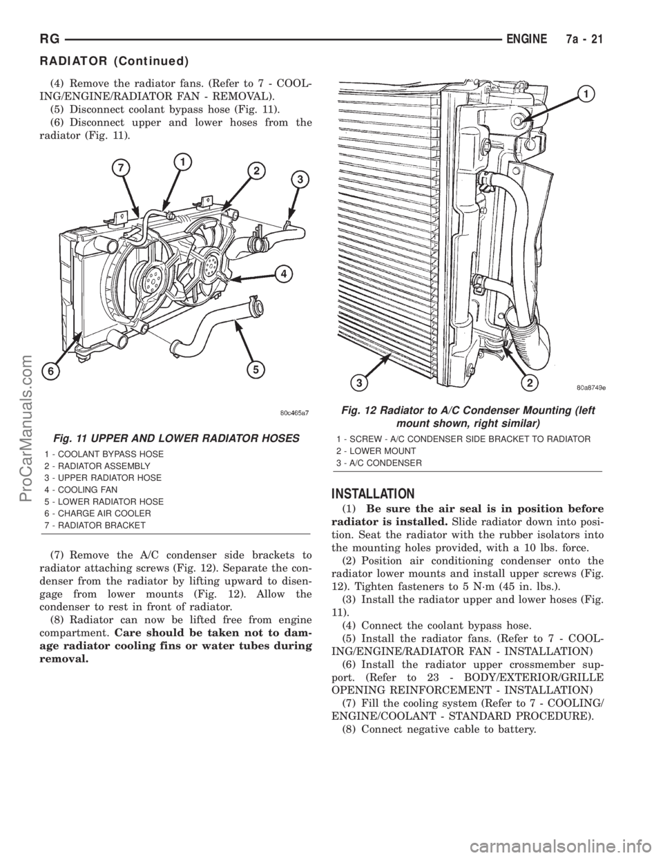
(4) Remove the radiator fans. (Refer to 7 - COOL-
ING/ENGINE/RADIATOR FAN - REMOVAL).
(5) Disconnect coolant bypass hose (Fig. 11).
(6) Disconnect upper and lower hoses from the
radiator (Fig. 11).
(7) Remove the A/C condenser side brackets to
radiator attaching screws (Fig. 12). Separate the con-
denser from the radiator by lifting upward to disen-
gage from lower mounts (Fig. 12). Allow the
condenser to rest in front of radiator.
(8) Radiator can now be lifted free from engine
compartment.Care should be taken not to dam-
age radiator cooling fins or water tubes during
removal.
INSTALLATION
(1)Be sure the air seal is in position before
radiator is installed.Slide radiator down into posi-
tion. Seat the radiator with the rubber isolators into
the mounting holes provided, with a 10 lbs. force.
(2) Position air conditioning condenser onto the
radiator lower mounts and install upper screws (Fig.
12). Tighten fasteners to 5 N´m (45 in. lbs.).
(3) Install the radiator upper and lower hoses (Fig.
11).
(4) Connect the coolant bypass hose.
(5) Install the radiator fans. (Refer to 7 - COOL-
ING/ENGINE/RADIATOR FAN - INSTALLATION)
(6) Install the radiator upper crossmember sup-
port. (Refer to 23 - BODY/EXTERIOR/GRILLE
OPENING REINFORCEMENT - INSTALLATION)
(7) Fill the cooling system (Refer to 7 - COOLING/
ENGINE/COOLANT - STANDARD PROCEDURE).
(8) Connect negative cable to battery.
Fig. 11 UPPER AND LOWER RADIATOR HOSES
1 - COOLANT BYPASS HOSE
2 - RADIATOR ASSEMBLY
3 - UPPER RADIATOR HOSE
4 - COOLING FAN
5 - LOWER RADIATOR HOSE
6 - CHARGE AIR COOLER
7 - RADIATOR BRACKET
Fig. 12 Radiator to A/C Condenser Mounting (left
mount shown, right similar)
1 - SCREW - A/C CONDENSER SIDE BRACKET TO RADIATOR
2 - LOWER MOUNT
3 - A/C CONDENSER
RGENGINE7a-21
RADIATOR (Continued)
ProCarManuals.com
Page 365 of 2321

INSTALLATION
(1) Install the PLG control module on the D-pillar
and install retaining screw. Torque the screw to 14.5
in. lbs.
(2) Connect the wire harness connections on the
PLG control module. Be certain to slide connector
locks to the locked position.
(3) Install the D-pillar trim panel on the vehicle.
Refer to the Body section for the procedure.
(4) Connect the negative battery cable.
(5) Using an appropriate scan tool, check any
erase any PLG control module diagnostic trouble
codes.
(6) Verify PLG system operation. Cycle the PLG
through one complete open and close cycle, this will
allow the PLG control module to relearn its cycle
with the new components.
POWERTRAIN CONTROL
MODULE
DESCRIPTION
The Powertrain Control Module (PCM) is a digital
computer containing a microprocessor (Fig. 10). The
PCM receives input signals from various switchesand sensors referred to as Powertrain Control Mod-
ule Inputs. Based on these inputs, the PCM adjusts
various engine and vehicle operations through
devices referred to as Powertrain Control Module
Outputs.
NOTE: PCM Inputs:
²Air Conditioning Pressure Transducer
²ASD Relay
²Battery Voltage
²Brake Switch
²Camshaft Position Sensor
²Crankshaft Position Sensor
²Distance Sensor (from transmission control mod-
ule)
²EGR Position Feedback
²Engine Coolant Temperature Sensor
²Heated Oxygen Sensors
²Ignition sense
²Intake Air Temperature Sensor
²Knock Sensor
²Leak Detection Pump Feedback
²Manifold Absolute Pressure (MAP) Sensor
²Park/Neutral (from transmission control module)
²PCI Bus
²Power Steering Pressure Switch
²Proportional Purge Sense
²SCI Receive
²Speed Control
Fig. 9 LIFTGATE CONTROL MODULE
1 - POWER LIFTGATE CONTROL MODULE
2 - MODULE RETAINING SCREWS
3 - D-PILLAR
4 - POWER LIFTGATE MOTOR
5 - MODULE ELECTRICAL CONNECTORS
Fig. 10 Powertrain Control Module (PCM)
1 - Battery
2 - Power Distribution Center
3 - Powertrain Control Module
8E - 8 ELECTRONIC CONTROL MODULESRS
POWER LIFTGATE MODULE (Continued)
ProCarManuals.com
Page 366 of 2321

²Throttle Position Sensor
²Torque Management Input (From TCM)
²Transaxle Control Module (TCM)
²Transaxle Gear Engagement (From TCM)
²Vehicle Speed (from transmission control mod-
ule)
NOTE: PCM Outputs:
²Air Conditioning Clutch Relay
²Automatic Shut Down (ASD) and Fuel Pump
Relays
²Data Link Connector (PCI and SCI Transmit)
²Double Start Override
²EGR Solenoid
²Fuel Injectors
²Generator Field
²High Speed Fan Relay
²Idle Air Control Motor
²Ignition Coils
²Leak Detection Pump
²Low Speed Fan Relay
²MTV Actuator
²Proportional Purge Solenoid
²SRV Valve
²Speed Control Relay
²Speed Control Vent Relay
²Speed Control Vacuum Relay
²8 Volt Output
²5 Volt Output
Based on inputs it receives, the powertrain control
module (PCM) adjusts fuel injector pulse width, idle
speed, ignition timing, and canister purge operation.
The PCM regulates the cooling fans, air conditioning
and speed control systems. The PCM changes gener-
ator charge rate by adjusting the generator field.
The PCM adjusts injector pulse width (air-fuel
ratio) based on the following inputs.
²Battery Voltage
²Intake Air Temperature Sensor
²Engine Coolant Temperature
²Engine Speed (crankshaft position sensor)
²Exhaust Gas Oxygen Content (heated oxygen
sensors)
²Manifold Absolute Pressure
²Throttle Position
The PCM adjusts engine idle speed through the
idle air control motor based on the following inputs.
²Brake Switch
²Engine Coolant Temperature
²Engine Speed (crankshaft position sensor)
²Park/Neutral (transmission gear selection)
²Transaxle Gear Engagement
²Throttle Position
²Vehicle Speed (from Transmission Control Mod-
ule)The PCM adjusts ignition timing based on the fol-
lowing inputs.
²Intake Air Temperature
²Engine Coolant Temperature
²Engine Speed (crankshaft position sensor)
²Knock Sensor
²Manifold Absolute Pressure
²Park/Neutral (transmission gear selection)
²Transaxle Gear Engagement
²Throttle Position
The automatic shut down (ASD) and fuel pump
relays are mounted externally, but turned on and off
by the powertrain control module through the same
circuit.
The camshaft and crankshaft signals are sent to
the powertrain control module. If the PCM does not
receive both signals within approximately one second
of engine cranking, it deactivates the ASD and fuel
pump relays. When these relays are deactivated,
power is shut off to the fuel injectors, ignition coils,
fuel pump and the heating element in each oxygen
sensor.
The PCM contains a voltage converter that
changes battery voltage to a regulated 8.0 volts. The
8.0 volts power the camshaft position sensor, crank-
shaft position sensor and vehicle speed sensor. The
PCM also provides a 5.0 volts supply for the engine
coolant temperature sensor, intake air temperature
sensor, manifold absolute pressure sensor and throt-
tle position sensor.
The PCM engine control strategy prevents reduced
idle speeds until after the engine operates for 320 km
(200 miles). If the PCM is replaced after 320 km (200
miles) of usage, update the mileage in new PCM. Use
the DRB scan tool to change the mileage in the PCM.
Refer to the appropriate Powertrain Diagnostic Man-
ual and the DRB scan tool.
DIAGNOSTIC TROUBLE CODE
DESCRIPTION
A Diagnostic Trouble Code (DTC) indicates the
PCM has recognized an abnormal condition in the
system.
Remember that DTC's are the results of a sys-
tem or circuit failure, but do not directly iden-
tify the failed component or components.
NOTE: For a list of DTC's, refer to the charts in this
section.
RSELECTRONIC CONTROL MODULES8E-9
POWERTRAIN CONTROL MODULE (Continued)
ProCarManuals.com
Page 378 of 2321

²Fuel system monitor
²EGR monitor
²Purge system monitor
²All inputs monitored for proper voltage range.
²All monitored components (refer to the Emission
section for On-Board Diagnostics).
The PCM compares the upstream and downstream
heated oxygen sensor inputs to measure catalytic
convertor efficiency. If the catalyst efficiency drops
below the minimum acceptable percentage, the PCM
stores a diagnostic trouble code in memory.
During certain idle conditions, the PCM may enter
a variable idle speed strategy. During variable idle
speed strategy the PCM adjusts engine speed based
on the following inputs.
²A/C sense
²Battery voltage
²Battery temperature
²Engine coolant temperature
²Engine run time
²Inlet/Intake air temperature
²Vehicle mileage
ACCELERATION MODE
This is a CLOSED LOOP mode. The PCM recog-
nizes an abrupt increase in Throttle Position sensor
output voltage or MAP sensor output voltage as a
demand for increased engine output and vehicle
acceleration. The PCM increases injector pulse width
in response to increased fuel demand.
DECELERATION MODE
This is a CLOSED LOOP mode. During decelera-
tion the following inputs are received by the PCM:
²A/C sense
²Battery voltage
²Inlet/Intake air temperature
²Engine coolant temperature
²Crankshaft position (engine speed)
²Exhaust gas oxygen content (upstream heated
oxygen sensor)
²Knock sensor
²Manifold absolute pressure
²Throttle position
²IAC motor control changes in response to MAP
sensor feedback
The PCM may receive a closed throttle input from
the Throttle Position Sensor (TPS) when it senses an
abrupt decrease in manifold pressure. This indicates
a hard deceleration. In response, the PCM may
momentarily turn off the injectors. This helps
improve fuel economy, emissions and engine braking.
WIDE-OPEN-THROTTLE MODE
This is an OPEN LOOP mode. During wide-open-
throttle operation, the following inputs are used by
the PCM:
²Inlet/Intake air temperature
²Engine coolant temperature
²Engine speed
²Knock sensor
²Manifold absolute pressure
²Throttle position
When the PCM senses a wide-open-throttle condi-
tion through the Throttle Position Sensor (TPS) it de-
energizes the A/C compressor clutch relay. This
disables the air conditioning system.
The PCM does not monitor the heated oxygen sen-
sor inputs during wide-open-throttle operation except
for downstream heated oxygen sensor and both
shorted diagnostics. The PCM adjusts injector pulse
width to supply a predetermined amount of addi-
tional fuel.
IGNITION SWITCH OFF MODE
When the operator turns the ignition switch to the
OFF position, the following occurs:
²All outputs are turned off, unless 02 Heater
Monitor test is being run. Refer to the Emission sec-
tion for On-Board Diagnostics.
²No inputs are monitored except for the heated
oxygen sensors. The PCM monitors the heating ele-
ments in the oxygen sensors and then shuts down.
STANDARD PROCEDURES - OBTAINING
DIAGNOSTIC TROUBLE CODES
BULB CHECK
Each time the ignition key is turned to the ON
position, the malfunction indicator (check engine)
lamp on the instrument panel should illuminate for
approximately 2 seconds then go out. This is done for
a bulb check. When the key is in the power on, but
engine off position, the MIL will remain illuminated
for regulatory purposes.
OBTAINING DTC'S USING DRB SCAN TOOL
(1) Connect the DRB scan tool to the data link
(diagnostic) connector. This connector is located in
the passenger compartment; at the lower edge of
instrument panel; near the steering column.
(2) Turn the ignition switch on and access the
ªRead Faultº screen.
(3) Record all the DTC's and ªfreeze frameº infor-
mation shown on the DRB scan tool.
RSELECTRONIC CONTROL MODULES8E-21
POWERTRAIN CONTROL MODULE (Continued)
ProCarManuals.com
Page 618 of 2321
WIRING
TABLE OF CONTENTS
page page
WIRING DIAGRAM INFORMATION...... 8Wa-01-1
COMPONENT INDEX................. 8Wa-02-1
POWER DISTRIBUTION.............. 8Wa-10-1
GROUND DISTRIBUTION............. 8Wa-15-1
BUS COMMUNICATIONS............. 8Wa-18-1
CHARGING SYSTEM................. 8Wa-20-1
STARTING SYSTEM................. 8Wa-21-1
FUEL/IGNITION SYSTEM............. 8Wa-30-1
TRANSMISSION CONTROL SYSTEM.... 8Wa-31-1
VEHICLE SPEED CONTROL........... 8Wa-33-1
ANTILOCK BRAKES.................. 8Wa-35-1
VEHICLE THEFT SECURITY SYSTEM.... 8Wa-39-1
INSTRUMENT CLUSTER.............. 8Wa-40-1
HORN/CIGAR LIGHTER/POWER OUTLET . 8Wa-41-1
AIR CONDITIONING-HEATER.......... 8Wa-42-1
AIRBAG SYSTEM................... 8Wa-43-1
INTERIOR LIGHTING................. 8Wa-44-1
BODY CONTROL MODULE............ 8Wa-45-1MESSAGE CENTER.................. 8Wa-46-1
AUDIO SYSTEM.................... 8Wa-47-1
REAR WINDOW DEFOGGER........... 8Wa-48-1
OVERHEAD CONSOLE................ 8Wa-49-1
FRONT LIGHTING................... 8Wa-50-1
REAR LIGHTING.................... 8Wa-51-1
TURN SIGNALS..................... 8Wa-52-1
WIPERS........................... 8Wa-53-1
TRAILER TOW...................... 8Wa-54-1
POWER WINDOWS.................. 8Wa-60-1
POWER DOOR LOCKS............... 8Wa-61-1
POWER MIRRORS.................. 8Wa-62-1
POWER SEATS..................... 8Wa-63-1
SPLICE INFORMATION............... 8Wa-70-1
CONNECTOR PIN-OUTS.............. 8Wa-80-1
CONNECTOR/GROUND LOCATIONS BUX . 8Wa-90-1
SPLICE LOCATIONS BUX............. 8Wa-95-1 RGWIRING
8Wa-1
ProCarManuals.com
Page 818 of 2321
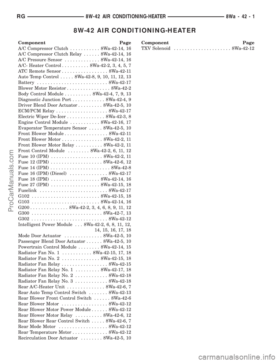
8W-42 AIR CONDITIONING-HEATER
Component Page
A/C Compressor Clutch........... 8Wa-42-14, 16
A/C Compressor Clutch Relay...... 8Wa-42-14, 16
A/C Pressure Sensor............. 8Wa-42-14, 16
A/C- Heater Control.......... 8Wa-42-2, 3, 4, 5, 7
ATC Remote Sensor................. 8Wa-42-11
Auto Temp Control..... 8Wa-42-8, 9, 10, 11, 12, 13
Battery.......................... 8Wa-42-17
Blower Motor Resistor................ 8Wa-42-2
Body Control Module.......... 8Wa-42-4, 7, 9, 13
Diagnostic Junction Port............ 8Wa-42-4, 9
Driver Blend Door Actuator......... 8Wa-42-5, 10
ECM/PCM Relay................... 8Wa-42-17
Electric Wiper De-Icer.............. 8Wa-42-3, 8
Engine Control Module........... 8Wa-42-16, 17
Evaporator Temperature Sensor..... 8Wa-42-5, 10
Front Blower Module................ 8Wa-42-11
Front Blower Motor............... 8Wa-42-2, 11
Front Blower Motor Relay.......... 8Wa-42-2, 11
Front Control Module........ 8Wa-42-2, 6, 11, 12
Fuse 10 (IPM)................... 8Wa-42-2, 11
Fuse 12 (IPM)................... 8Wa-42-6, 12
Fuse 14 (IPM)...................... 8Wa-42-8
Fuse 16 (IPM) (Diesel).............. 8Wa-42-17
Fuse 18 (IPM).................. 8Wa-42-14, 16
Fuse 27 (IPM).................. 8Wa-42-15, 18
Fuselink......................... 8Wa-42-17
G102......................... 8Wa-42-15, 18
G103......................... 8Wa-42-14, 16
G200.............. 8Wa-42-2, 3, 4, 6, 8, 9, 11, 12
G300.......................... 8Wa-42-7, 13
G302............................ 8Wa-42-12
Intelligent Power Module . . . 8Wa-42-2, 6, 8, 11, 12,
14, 15, 16, 17, 18
Mode Door Actuator.............. 8Wa-42-5, 10
Passenger Blend Door Actuator...... 8Wa-42-5, 10
Powertrain Control Module........ 8Wa-42-14, 15
Radiator Fan No. 1........... 8Wa-42-15, 17, 18
Radiator Fan No. 2.............. 8Wa-42-15, 18
Radiator Fan Relay................. 8Wa-42-15
Radiator Fan Relay No. 1......... 8Wa-42-17, 18
Radiator Fan Relay No. 2............ 8Wa-42-18
Radiator Fan Relay No. 3............ 8Wa-42-18
Rear A/C-Heater Unit.............. 8Wa-42-6, 7
Rear Auto Temp Control Switch....... 8Wa-42-13
Rear Blower Front Control Switch...... 8Wa-42-6
Rear Blower Motor................. 8Wa-42-12
Rear Blower Motor Power Module...... 8Wa-42-12
Rear Blower Motor Relay.......... 8Wa-42-6, 12
Rear Blower Rear Control Switch..... 8Wa-42-6, 7
Rear Mode Motor.................. 8Wa-42-12
Rear Temperature Motor............. 8Wa-42-12
Recirculation Door Actuator........ 8Wa-42-5, 10Component Page
TXV Solenoid..................... 8Wa-42-12
RG8W-42 AIR CONDITIONING-HEATER8Wa-42-1
ProCarManuals.com