2001 DODGE TOWN AND COUNTRY ignition
[x] Cancel search: ignitionPage 605 of 2321
OPERATION
Each Sentry Key has a unique transponder identi-
fication code permanently programmed into it by the
manufacturer. Likewise, the SKIM has a unique
9Secret Key9code programmed into it by the manu-
facturer as well. When a Sentry Key is programmed
into the memory of the SKIM, the SKIM stores the
transponder identification code from the Sentry Key,
and the Sentry Key learns the9Secret Key9code from
the SKIM. Once the Sentry Key learns the9Secret
Key9code of the SKIM, it is also permanently pro-
grammed into the transponder's memory. Therefore,
blank keys for the SKIS must be programmed by the
SKIM in addition to being cut to match the mechan-
ical coding of the ignition lock cylinder. Refer to Elec-
trical, Vehicle Theft Security, Transponder Key,
Standard Procedure - Transponder Programming.
The Sentry Key's transponder is within the range
of the SKIM's transceiver antenna ring when it is
inserted into the ignition lock cylinder. When the
ignition switch is turned to the ON position, the
SKIM communicates with the Sentry Key via a radio
frequency (RF) signal. The SKIM determines if a
valid key is present based on the information it
receives from the Sentry Key. If a valid key is
detected, that fact is communicated to the PCM via
the PCI bus and the vehicle is allowed to continue
running. If an invalid key is received by the PCM or
no status at all is communicated, the vehicle will
stall after two (2) seconds of running. The indicator
light will be flashing at this point. The Sentry Key's
transponder can not be repaired. If it is faulty or
damaged, it must be replaced.
Common communication problems:
²Two transponder keys too close together.
²Speed Pass too close to transponder key.
Solid indicator that there is a system failure.
²Loss of PCM communication.
²Failed antenna circuit.
STANDARD PROCEDURE - TRANSPONDER
PROGRAMMING
USING A DRB IIITSCAN TOOL
All Sentry Keys included with the vehicle are pre-
programmed to work with the Sentry Key Immobi-
lizer System (SKIS) when it is shipped from the
factory. The Sentry Key Immobilizer Module (SKIM)
can be programmed to recognize up to a total of eight
Sentry Keys. When programming a blank Sentry Key
transponder, the key must first be cut to match the
ignition lock cylinder of the vehicle for which it will
be used. The vehicle's four digit PIN code will be
required to complete this task since you will need it
to enter the Secured Access Mode in the SKIM. Thefollowing steps must be completed using a DRB IIIt
scan tool:
(1) Insert the blank key into the ignition and turn
it to the RUN position.
(2) Using a DRB IIItscan tool, select9Theft
Alarm,99SKIM,99Miscellaneous,9and then9Program
New Key.9
(3) Enter the four digit PIN code using the DRB
IIItscan tool. When programming is completed, the
SKIM will exit Secured Access Mode and the DRB
IIItscan tool will display the results of your attempt
to program the key. One of five distinct results may
be displayed. All five are listed below:
²(Programming Successful(is displayed if the
Sentry Key programming is successful.
²(Learned Key in Ignition(is displayed if the
key in the ignition has already been programmed
into that vehicle's SKIM.
²(Eight Keys Already Learned (At The Maxi-
mum) Programming Not Done(is displayed if
eight keys have already been programmed into the
SKIM. In this case, if a new key needs to be added
due to a lost or defective key, the9Erase All Keys9
command (which requires entering the Secured
Access Mode) has to be performed. Following the
9Erase All Keys9command, all keys that will be used
to operate the vehicleMUSTbe reprogrammed to
the SKIM.
²(Programming Not Attempted(is displayed
after an9Erase All Keys9function is executed.
²(Programming Key Failed(is displayed if fur-
ther diagnosis is required.
To learn additional keys, turn the ignition OFF,
remove the learned key, insert the next new blank
key, and repeat the steps from the beginning.
ªCUSTOMER LEARNº MODE
This feature is only available on domestic vehicles
or those which have a U.S. country code designator.
This procedure requires access to at least two valid
Sentry Keys. If two valid Sentry Keys are not avail-
able, Sentry Key programming will require the use of
a DRB IIItscan tool.
The steps required to program Sentry Keys with
two valid Sentry Keys follows:
(1) Obtain the blank Sentry Key(s) that need to be
programmed. Cut the keys to match the ignition lock
cylinder mechanical key codes.
(2) Insert one of the two valid Sentry Keys into the
ignition switch and turn the ignition switch to the
ON position.
(3) After the ignition switch has been in the ON
position for longer than three seconds, but no more
than fifteen seconds, cycle the ignition switch back to
8Q - 4 VEHICLE THEFT SECURITYRS
TRANSPONDER KEY (Continued)
ProCarManuals.com
Page 606 of 2321
the OFF position. Replace the first valid Sentry Key
in the ignition lock cylinder with the second valid
Sentry Key and turn the ignition switch back to the
ON position. The second valid Sentry Key must be
inserted within 15 seconds of removing the first valid
Sentry key.
(4) About ten seconds after the completion of Step
3, the indicator light will start to flash and a single
audible chime tone will sound to indicate that the
system has entered the9Customer Learn9program-
ming mode.
(5) Within sixty seconds of entering the9Customer
Learn9programming mode, turn the ignition switch
to the OFF position, replace the valid Sentry Key
with a blank Sentry Key transponder, and turn the
ignition switch back to the ON position.
(6) About ten seconds after the completion of Step
5, a single audible chime tone will sound and the
indicator light will stop flashing and stay on solid for
three seconds and then turn off to indicate that the
blank Sentry Key has been successfully programmed.
The SKIS will immediately exit the9Customer
Learn9programming mode and the vehicle may be
started using the newly programmed Sentry Key.
These steps must be completed in their entirety for
each additional Sentry Key to be programmed. If any
of the above steps are not completed in the given
sequence, or within the allotted time, the SKIS will
exit the9Customer Learn9programming mode and
the programming will be unsuccessful. The SKIS will
also automatically exit the9Customer Learn9pro-
gramming mode if:
²It sees a non-blank Sentry Key when it should
see a blank.
²If it has already programmed eight (8) valid
Sentry Keys.
²If the ignition switch is turned to the OFF posi-
tion for more than about fifty (50) seconds.
NOTE: If you attempt to start the vehicle while in
ªCustomer Learnº mode (LED flashing), the vehicle
will behave as though an invalid key is being used
(i.e. the engine will stall after two (2) seconds of
running). No faults will be logged.
NOTE: Once a Sentry Key has been programmed to
a particular vehicle, it cannot be used on any other
vehicle.VTSS/SKIS INDICATOR LAMP
DESCRIPTION
The Sentry Key Immobilizer System (SKIS) uses
an indicator light to convey information on the status
of the system to the customer. This light is shared
with the Vehicle Theft Security System (VTSS). The
light is located in the Message Center. The indicator
light is controlled by the Body Control Module (BCM)
based upon messages it receives from the Sentry Key
Immobilizer Module (SKIM) on the PCI bus.
OPERATION
The BCM performs a four second bulb check,
regardless of SKIM messages. After the bulb check,
the lamp is controlled according to SKIM messages.
Then, the SKIM sends messages to the BCM to oper-
ate the light based upon the results of the SKIS self
tests. The light may be actuated in two possible
ways, flashing or on solid. If the light comes on and
stays on solid after a power-up test, this indicates
that the SKIM has detected a system malfunction. If
the SKIM detects an invalid key when the ignition
switch is moved to the ON position, it sends a mes-
sage on the PCI bus to the BCM, to flash the light.
The SKIM can also send a message to flash the light
and generate a single audible chime at the same
time. These two events occurring simultaneously
indicate that the SKIS has been placed into the9Cus-
tomer Learn9mode. Refer to Electrical, Vehicle Theft
Security, Transponder Key, Standard Procedure -
Transponder Programming for more information on
the9Customer Learn9mode. If the light comes on
and stays on after the power-up test, diagnosis of the
SKIS should be performed using a DRB IIItscan tool
and the appropriate Body Diagnostic Procedures
manual. The light is not a serviceable component.
RSVEHICLE THEFT SECURITY8Q-5
TRANSPONDER KEY (Continued)
ProCarManuals.com
Page 608 of 2321
WIPERS/WASHERS
TABLE OF CONTENTS
page page
WIPERS/WASHERS
DESCRIPTION............................1
OPERATION.............................1
DIAGNOSIS AND TESTING..................2
FRONT WIPER SYSTEM..................2
REAR WIPER SYSTEM...................2
FRONT WIPER/WASHER SWITCH...........2
FAILED PARK SWITCH...................2
FRONT WIPER ARMS
REMOVAL...............................4
INSTALLATION............................4
ADJUSTMENTS...........................4
FRONT WIPER MOTOR
REMOVAL...............................5
INSTALLATION............................5
FRONT WIPER UNIT
REMOVAL...............................5
INSTALLATION............................6
REAR WIPER ARM
REMOVAL...............................6
INSTALLATION............................7
REAR WIPER MOTOR
REMOVAL...............................7INSTALLATION............................7
REAR WIPER/WASHER SWITCH
DESCRIPTION............................7
OPERATION.............................7
WASHER HOSES
REMOVAL...............................7
INSTALLATION............................8
WASHER RESERVOIR
REMOVAL...............................8
INSTALLATION............................8
WIPER BLADES
REMOVAL...............................9
CLEANING...............................9
INSTALLATION............................9
WIPER BLADE ELEMENTS
REMOVAL...............................9
INSTALLATION...........................10
WIPER LINKAGE
REMOVAL..............................10
INSTALLATION...........................10
WIPERS/WASHERS
DESCRIPTION
FRONT WIPER/WASHER SYSTEM
The windshield wipers can be operated with the
windshield wiper switch when the ignition switch is
in the RUN or ACCESSORY positions. The wind-
shield wiper system is protected by a 30 amp fuse (9)
located in the Power Distribution Center (PDC) part
of the Integrated Power Module (IPM) in the engine
compartment. The wiper/washer switch is integral to
the multi-function switch. It is a resistive MUX
switch that sends inputs to the BCM to operate the
wiper/washer system.
REAR WIPER/WASHER SYSTEM
The rear windshield wiper and washers can be
operated when the ignition switch is in the RUN or
ACCESSORY positions.
OPERATION
FRONT WIPER/WASHER SYSTEM
The windshield washer circuit is protected by a 9
amp PTC located in the Junction Block. The wiper
motor has permanent magnetic fields. The speeds are
determined by current flow to the appropriate set of
brushes inside the motor. The current flow is con-
trolled by the multi-function switch stalk mounted
wiper switch, high speed/low speed relays located in
the Power Distribution Center (PDC) part of the
Integrated Power Module (IPM) in the engine com-
partment. The speed sensitive intermittent wiper is
controlled by the Body Control Module (BCM). The
intermittent mode, with the vehicle traveling greater
than 10.4 mph, has a range of 0.5 to 18 seconds.
With the vehicle traveling less than 10.4 mph, and
the time delay is not adjusted, time delay doubles to
a range of 1 to 36 seconds. The wiper arms will park
at the base of the windshield just above the cowl
cover after the wiper switch is turned OFF.
RSWIPERS/WASHERS8R-1
ProCarManuals.com
Page 609 of 2321
The windshield wiper motor and linkage is located
in an integral wiper unit at the rear of the engine
compartment. The wiper unit must be removed to
gain access to the wiper motor.
REAR WIPER/WASHER SYSTEM
When continuous rear wiper operation is required,
the Body Control Module (BCM) will provide ignition
ON voltage to the rear wiper motor. When the wiper
switch is turned OFF, the BCM provides circuit
ground to operate the motor until the wipe cycle is
complete and the wiper arm returns to the base of
the rear window.
When intermittent rear wiper mode is selected, the
wiper motor will cycle every 7 seconds. The intermit-
tent delay time is also adjusted based upon vehicle
speed. With the vehicle traveling greater at 50 mph,
the cycle changes to every 5 seconds. DIAGNOSIS
AND TESTING
DIAGNOSIS AND TESTING - FRONT WIPER
SYSTEM
The windshield wiper system operates in several
modes:
²Low and high speed normal wipe
²Speed sensitive intermittent wipe
²Wipe after wash
²Pulse wipe
²Park (switch OFF)
The windshield wiper circuits are continuously
monitored and controlled by the Body Control Mod-
ule (BCM). If a problem occurs in the electronic com-
ponents, wiring, switch (except integral motor park
switch) and wiper motor a Diagnostic Trouble Code
(DTC) will be stored in the BCM memory. DTC's can
be retrieved using a DRB IIItscan tool. Refer to the
proper Body Diagnostic Procedures manual for DTC
descriptions and retrieval information.
The windshield wiper park switch and circuit is
monitored by the BCM. The park switch and circuit
can be tested using the Wiper System Diagnosis
table.
DIAGNOSIS AND TESTING - REAR WIPER
SYSTEM
The rear window wiper system operates in several
modes:
²Continuous wipe
²Intermittent wipe
²Wash
²Wipe after wash
The windshield wiper circuits are continuously
monitored and controlled by the Body Control Mod-
ule (BCM). If a problem occurs in the electronic com-
ponents, wiring, switch (except integral motor parkswitch) and wiper motor a Diagnostic Trouble Code
(DTC) will be stored in the BCM memory. The
DTC(s) can be retrieved using a DRB IIItscan tool.
DIAGNOSIS AND TESTING - FRONT
WIPER/WASHER SWITCH
To test the front wiper/washer portion of the multi-
function switch:
(1) Remove the multi-function switch (Refer to 8 -
ELECTRICAL/LAMPS/LIGHTING - EXTERIOR/
MULTI-FUNCTION SWITCH - REMOVAL).
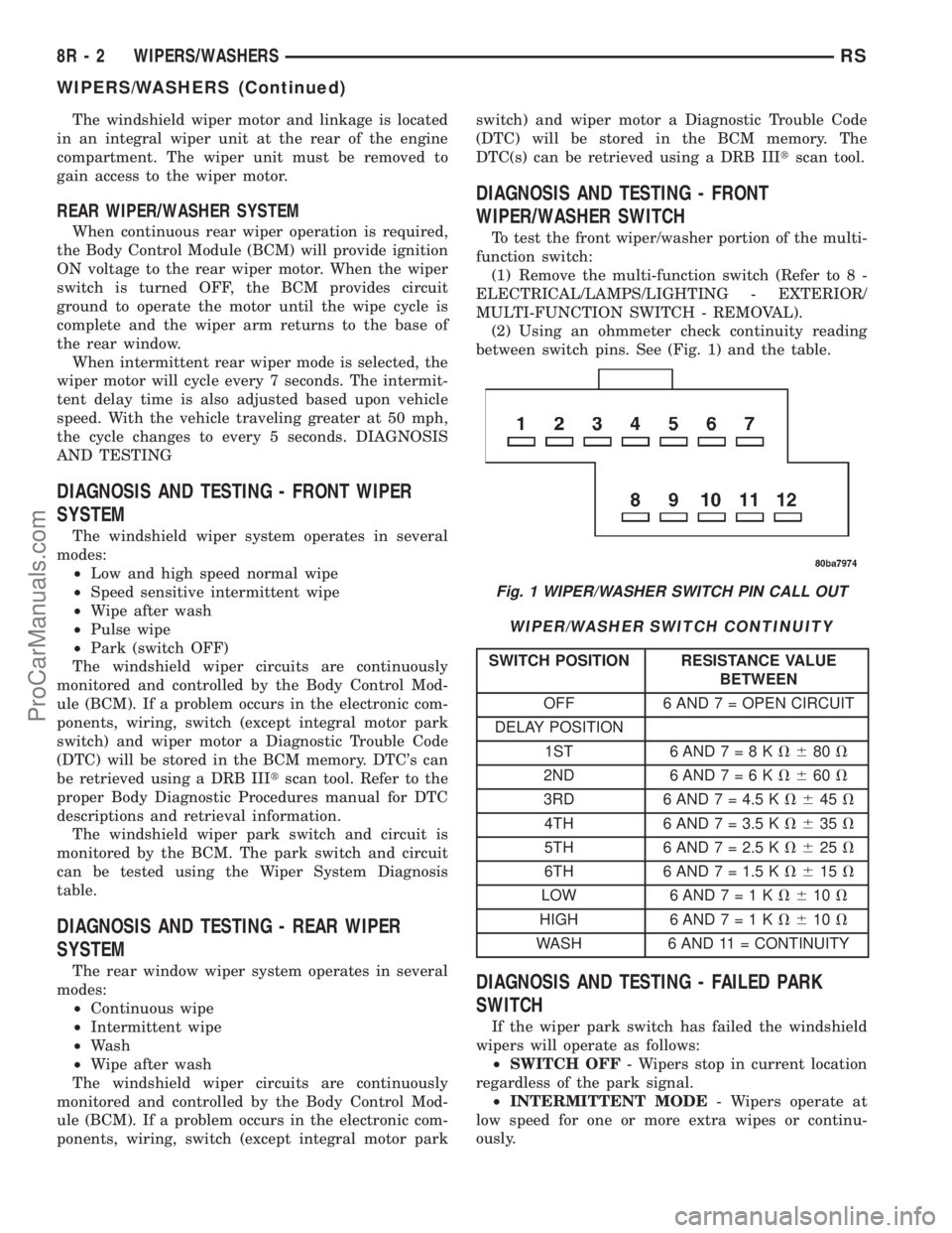
(2) Using an ohmmeter check continuity reading
between switch pins. See (Fig. 1) and the table.
WIPER/WASHER SWITCH CONTINUITY
SWITCH POSITION RESISTANCE VALUE
BETWEEN
OFF 6 AND 7 = OPEN CIRCUIT
DELAY POSITION
1ST 6AND7=8KV680V
2ND 6AND7=6KV660V
3RD 6 AND 7 = 4.5 KV645V
4TH 6 AND 7 = 3.5 KV635V
5TH 6 AND 7 = 2.5 KV625V
6TH 6 AND 7 = 1.5 KV615V
LOW 6AND7=1KV610V
HIGH 6 AND7=1KV610V
WASH 6 AND 11 = CONTINUITY
DIAGNOSIS AND TESTING - FAILED PARK
SWITCH
If the wiper park switch has failed the windshield
wipers will operate as follows:
²SWITCH OFF- Wipers stop in current location
regardless of the park signal.
²INTERMITTENT MODE- Wipers operate at
low speed for one or more extra wipes or continu-
ously.
Fig. 1 WIPER/WASHER SWITCH PIN CALL OUT
8R - 2 WIPERS/WASHERSRS
WIPERS/WASHERS (Continued)
ProCarManuals.com
Page 618 of 2321
WIRING
TABLE OF CONTENTS
page page
WIRING DIAGRAM INFORMATION...... 8Wa-01-1
COMPONENT INDEX................. 8Wa-02-1
POWER DISTRIBUTION.............. 8Wa-10-1
GROUND DISTRIBUTION............. 8Wa-15-1
BUS COMMUNICATIONS............. 8Wa-18-1
CHARGING SYSTEM................. 8Wa-20-1
STARTING SYSTEM................. 8Wa-21-1
FUEL/IGNITION SYSTEM............. 8Wa-30-1
TRANSMISSION CONTROL SYSTEM.... 8Wa-31-1
VEHICLE SPEED CONTROL........... 8Wa-33-1
ANTILOCK BRAKES.................. 8Wa-35-1
VEHICLE THEFT SECURITY SYSTEM.... 8Wa-39-1
INSTRUMENT CLUSTER.............. 8Wa-40-1
HORN/CIGAR LIGHTER/POWER OUTLET . 8Wa-41-1
AIR CONDITIONING-HEATER.......... 8Wa-42-1
AIRBAG SYSTEM................... 8Wa-43-1
INTERIOR LIGHTING................. 8Wa-44-1
BODY CONTROL MODULE............ 8Wa-45-1MESSAGE CENTER.................. 8Wa-46-1
AUDIO SYSTEM.................... 8Wa-47-1
REAR WINDOW DEFOGGER........... 8Wa-48-1
OVERHEAD CONSOLE................ 8Wa-49-1
FRONT LIGHTING................... 8Wa-50-1
REAR LIGHTING.................... 8Wa-51-1
TURN SIGNALS..................... 8Wa-52-1
WIPERS........................... 8Wa-53-1
TRAILER TOW...................... 8Wa-54-1
POWER WINDOWS.................. 8Wa-60-1
POWER DOOR LOCKS............... 8Wa-61-1
POWER MIRRORS.................. 8Wa-62-1
POWER SEATS..................... 8Wa-63-1
SPLICE INFORMATION............... 8Wa-70-1
CONNECTOR PIN-OUTS.............. 8Wa-80-1
CONNECTOR/GROUND LOCATIONS BUX . 8Wa-90-1
SPLICE LOCATIONS BUX............. 8Wa-95-1 RGWIRING
8Wa-1
ProCarManuals.com
Page 620 of 2321
8W-01 WIRING DIAGRAM INFORMATION
TABLE OF CONTENTS
page page
WIRING DIAGRAM INFORMATION
DESCRIPTION............................1
WARNING...............................5
DIAGNOSIS AND TESTING..................5
WIRING HARNESS......................5
STANDARD PROCEDURE...................6
TESTING OF VOLTAGE POTENTIAL.........6
TESTING FOR CONTINUITY...............6
TESTING FOR SHORT TO GROUND.........6
TESTING FOR A SHORT TO GROUND ON
FUSES POWERING SEVERAL LOADS........7
TESTING FOR VOLTAGE DROP............7
SPECIAL TOOLS..........................8
CONNECTOR - AUGAT
REMOVAL...............................8
INSTALLATION............................8CONNECTOR - MOLEX
REMOVAL...............................9
INSTALLATION............................9
CONNECTOR - THOMAS AND BETTS
REMOVAL...............................9
INSTALLATION...........................10
DIODE
REMOVAL..............................10
INSTALLATION...........................10
TERMINAL
REMOVAL..............................11
INSTALLATION...........................11
WIRE
STANDARD PROCEDURE..................11
STANDARD PROCEDURE - WIRE SPLICING . . 11
WIRING DIAGRAM
INFORMATION
DESCRIPTION - HOW TO USE WIRING
DIAGRAMS
DaimlerChrysler Corporation wiring diagrams are
designed to provide information regarding the vehi-
cles wiring content. In order to effectively use the
wiring diagrams to diagnose and repair
DaimlerChrysler Corporation vehicles, it is important
to understand all of their features and characteris-
tics.
Diagrams are arranged such that the power (B+)
side of the circuit is placed near the top of the page,
and the ground (B-) side of the circuit is placed near
the bottom of the page (Fig. 1).
All switches, components, and modules are shown
in the at rest position with the doors closed and the
key removed from the ignition (Fig. 2).Components are shown two ways. A solid line
around a component indicates that the component is
complete. A dashed line around the component indi-
cates that the component is being shown is not com-
plete. Incomplete components have a reference
number to indicate the page where the component is
shown complete.
It is important to realize that no attempt is made
on the diagrams to represent components and wiring
as they appear on the vehicle. For example, a short
piece of wire is treated the same as a long one. In
addition, switches and other components are shown
as simply as possible, with regard to function only.
SYMBOLS
International symbols are used throughout the wir-
ing diagrams. These symbols are consistent with
those being used around the world (Fig. 3).
RG8W-01 WIRING DIAGRAM INFORMATION8Wa-01-1
ProCarManuals.com
Page 624 of 2321
TERMINOLOGY
This is a list of terms and definitions used in the
wiring diagrams.
LHD .................Left Hand Drive Vehicles
RHD................Right Hand Drive Vehicles
ATX . . Automatic Transmissions-Front Wheel Drive
MTX....Manual Transmissions-Front Wheel Drive
AT ....Automatic Transmissions-Rear Wheel Drive
MT .....Manual Transmissions-Rear Wheel Drive
SOHC...........Single Over Head Cam Engine
DOHC..........Double Over Head Cam Engine
Built-Up-Export.......... Vehicles Built For Sale
In Markets Other Than North America
Except-Built-Up-Export.... Vehicles Built For Sale
In North America
WARNINGS - GENERAL
WARNINGSprovide information to prevent per-
sonal injury and vehicle damage. Below is a list of
general warnings that should be followed any time a
vehicle is being serviced.
WARNING:: ALWAYS WEAR SAFETY GLASSES FOR
EYE PROTECTION.
WARNING: USE SAFETY STANDS ANYTIME A PRO-
CEDURE REQUIRES BEING UNDER A VEHICLE.
WARNING: BE SURE THAT THE IGNITION SWITCH
ALWAYS IS IN THE OFF POSITION, UNLESS THE
PROCEDURE REQUIRES IT TO BE ON.
WARNING: SET THE PARKING BRAKE WHEN
WORKING ON ANY VEHICLE. AN AUTOMATIC
TRANSMISSION SHOULD BE IN PARK. A MANUAL
TRANSMISSION SHOULD BE IN NEUTRAL.
WARNING: OPERATE THE ENGINE ONLY IN A
WELL-VENTILATED AREA.
WARNING: KEEP AWAY FROM MOVING PARTS
WHEN THE ENGINE IS RUNNING, ESPECIALLY THE
FAN AND BELTS.
WARNING: TO PREVENT SERIOUS BURNS, AVOID
CONTACT WITH HOT PARTS SUCH AS THE RADIA-
TOR, EXHAUST MANIFOLD(S), TAIL PIPE, CATA-
LYTIC CONVERTER AND MUFFLER.WARNING: DO NOT ALLOW FLAME OR SPARKS
NEAR THE BATTERY. GASES ARE ALWAYS
PRESENT IN AND AROUND THE BATTERY.
WARNING: ALWAYS REMOVE RINGS, WATCHES,
LOOSE HANGING JEWELRY AND LOOSE CLOTH-
ING.
DIAGNOSIS AND TESTING - WIRING HARNESS
TROUBLESHOOTING TOOLS
When diagnosing a problem in an electrical circuit
there are several common tools necessary. These tools
are listed and explained below.
²Jumper Wire - This is a test wire used to con-
nect two points of a circuit. It can be used to bypass
an open in a circuit.
WARNING: NEVER USE A JUMPER WIRE ACROSS
A LOAD, SUCH AS A MOTOR, CONNECTED
BETWEEN A BATTERY FEED AND GROUND.
²Voltmeter - Used to check for voltage on a cir-
cuit. Always connect the black lead to a known good
ground and the red lead to the positive side of the
circuit.
CAUTION: Most of the electrical components used
in today's vehicles are Solid State. When checking
voltages in these circuits, use a meter with a 10 -
megohm or greater impedance rating.
²Ohmmeter - Used to check the resistance
between two points of a circuit. Low or no resistance
in a circuit means good continuity.
CAUTION: Most of the electrical components used
in today's vehicles are Solid State. When checking
resistance in these circuits use a meter with a 10 -
megohm or greater impedance rating. In addition,
make sure the power is disconnected from the cir-
cuit. Circuits that are powered up by the vehicle's
electrical system can cause damage to the equip-
ment and provide false readings.
²Probing Tools - These tools are used for probing
terminals in connectors (Fig. 4)Select the proper size
tool from Special Tool Package 6807, and insert it
into the terminal being tested. Use the other end of
the tool to insert the meter probe.
RG8W-01 WIRING DIAGRAM INFORMATION8Wa-01-5
WIRING DIAGRAM INFORMATION (Continued)
ProCarManuals.com
Page 625 of 2321
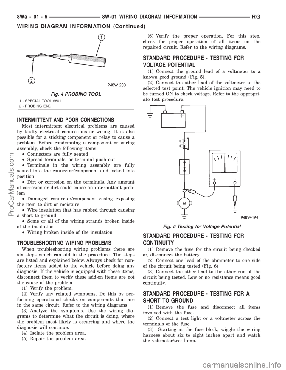
INTERMITTENT AND POOR CONNECTIONS
Most intermittent electrical problems are caused
by faulty electrical connections or wiring. It is also
possible for a sticking component or relay to cause a
problem. Before condemning a component or wiring
assembly, check the following items.
²Connectors are fully seated
²Spread terminals, or terminal push out
²Terminals in the wiring assembly are fully
seated into the connector/component and locked into
position
²Dirt or corrosion on the terminals. Any amount
of corrosion or dirt could cause an intermittent prob-
lem
²Damaged connector/component casing exposing
the item to dirt or moisture
²Wire insulation that has rubbed through causing
a short to ground
²Some or all of the wiring strands broken inside
of the insulation
²Wiring broken inside of the insulation
TROUBLESHOOTING WIRING PROBLEMS
When troubleshooting wiring problems there are
six steps which can aid in the procedure. The steps
are listed and explained below. Always check for non-
factory items added to the vehicle before doing any
diagnosis. If the vehicle is equipped with these items,
disconnect them to verify these add-on items are not
the cause of the problem.
(1) Verify the problem.
(2) Verify any related symptoms. Do this by per-
forming operational checks on components that are
in the same circuit. Refer to the wiring diagrams.
(3) Analyze the symptoms. Use the wiring dia-
grams to determine what the circuit is doing, where
the problem most likely is occurring and where the
diagnosis will continue.
(4) Isolate the problem area.
(5) Repair the problem area.(6) Verify the proper operation. For this step,
check for proper operation of all items on the
repaired circuit. Refer to the wiring diagrams.
STANDARD PROCEDURE - TESTING FOR
VOLTAGE POTENTIAL
(1) Connect the ground lead of a voltmeter to a
known good ground (Fig. 5).
(2) Connect the other lead of the voltmeter to the
selected test point. The vehicle ignition may need to
be turned ON to check voltage. Refer to the appropri-
ate test procedure.
STANDARD PROCEDURE - TESTING FOR
CONTINUITY
(1) Remove the fuse for the circuit being checked
or, disconnect the battery.
(2) Connect one lead of the ohmmeter to one side
of the circuit being tested (Fig. 6)
(3) Connect the other lead to the other end of the
circuit being tested. Low or no resistance means good
continuity.
STANDARD PROCEDURE - TESTING FOR A
SHORT TO GROUND
(1) Remove the fuse and disconnect all items
involved with the fuse.
(2) Connect a test light or a voltmeter across the
terminals of the fuse.
(3) Starting at the fuse block, wiggle the wiring
harness about six to eight inches apart and watch
the voltmeter/test lamp.
Fig. 4 PROBING TOOL
1 - SPECIAL TOOL 6801
2 - PROBING END
Fig. 5 Testing for Voltage Potential
8Wa - 01 - 6 8W-01 WIRING DIAGRAM INFORMATIONRG
WIRING DIAGRAM INFORMATION (Continued)
ProCarManuals.com