Page 1809 of 2321
REVERSE GEAR
Engine power is transmitted to the input shaft via
the clutch assembly and the input shaft turns. The
input shaft reverse gear is integral to the input
shaft, and is in constant mesh with the reverse idler
gear. The reverse idler gear, which reverses the rota-
tion of the intermediate shaft, is in constant mesh
with the intermediate shaft reverse gear. Because of
this constant mesh, the intermediate shaft reversegear freewheels until reverse gear is selected. As the
gearshift lever is moved to the reverse gear position,
the 5-R fork moves the 5-R synchronizer sleeve
towards the intermediate shaft reverse gear. The
synchronizer sleeve engages the reverse gear clutch
teeth, fixing the gear to the intermediate shaft, and
allowing power to transmit through the intermediate
shaft to the differential (in reverse) (Fig. 9).
Fig. 9 Reverse Gear Operation
21a - 10 T850 MANUAL TRANSAXLERG
T850 MANUAL TRANSAXLE (Continued)
ProCarManuals.com
Page 1819 of 2321

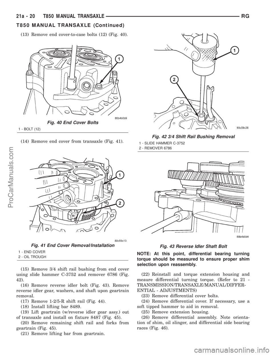
(13) Remove end cover-to-case bolts (12) (Fig. 40).
(14) Remove end cover from transaxle (Fig. 41).
(15) Remove 3/4 shift rail bushing from end cover
using slide hammer C-3752 and remover 6786 (Fig.
42).
(16) Remove reverse idler bolt (Fig. 43). Remove
reverse idler gear, washers, and shaft upon geartrain
removal.
(17) Remove 1-2/5-R shift rail (Fig. 44).
(18) Install lifting bar 8489.
(19) Lift geartrain (w/reverse idler gear assy.) out
of transaxle and install on fixture 8487 (Fig. 45).
(20) Remove remaining shift rail and forks from
geartrain (Fig. 45).
(21) Remove lifting bar from geartrain.NOTE: At this point, differential bearing turning
torque should be measured to ensure proper shim
selection upon reassembly.
(22) Reinstall and torque extension housing and
meaure differential turning torque. (Refer to 21 -
TRANSMISSION/TRANSAXLE/MANUAL/DIFFER-
ENTIAL - ADJUSTMENTS)
(23) Remove differential cover bolts.
(24) Remove differential cover. If necessary, use a
soft tipped hammer to aid in removal.
(25) Remove extension housing.
(26) Remove differential assembly. Note orienta-
tion of shim, oil slinger, and differential side bearing
races (Fig. 46).
Fig. 40 End Cover Bolts
1 - BOLT (12)
Fig. 41 End Cover Removal/Installation
1 - END COVER
2 - OIL TROUGH
Fig. 42 3/4 Shift Rail Bushing Removal
1 - SLIDE HAMMER C-3752
2 - REMOVER 6786
Fig. 43 Reverse Idler Shaft Bolt
21a - 20 T850 MANUAL TRANSAXLERG
T850 MANUAL TRANSAXLE (Continued)
ProCarManuals.com
Page 1820 of 2321
(27) Remove differential chip collector magnet and
clean (Fig. 47).Magnet is adhered with RTV, and
may require force to remove.
(28) Remove intermediate shaft bearing race with
puller 8472 (Fig. 48).
(29) Remove shift rail bushing from case with
remover 6786 and slide hammer C-3752 (Fig. 49).
(30) Remove input shaft bearing using an arbor
press and tool 8474 (Fig. 50).
Fig. 44 1/2-5/R Shift Rail Removal/Installation
1 - 1/2-5/R SHIFT RAIL
Fig. 45 Shift Fork/Rail Orientation
1 - 5/R FORK
2 - 3/4 RAIL ASSEMBLY
3 - 3/4 FORK
4 - 1/2 FORK
Fig. 46 Differential Shim/Slinger Orientation
1 - SLINGER
2 - BEARING RACE
3 - DIFFERENTIAL ASSEMBLY
4 - SHIM (SELECT)
Fig. 47 Differential Magnet
1 - MAGNET
RGT850 MANUAL TRANSAXLE21a-21
T850 MANUAL TRANSAXLE (Continued)
ProCarManuals.com
Page 1821 of 2321
ASSEMBLY
NOTE: When assembling this transaxle, always use
NEW snap rings.
NOTE: Before assembling transaxle, differential
turning torque must be measured and adjusted.
(Refer to 21 - TRANSMISSION/TRANSAXLE/MANU-
AL/DIFFERENTIAL - ADJUSTMENTS). Differential
turning torque must be measured with geartrain out
of case.
(1) Install input shaft bearing using an arbor press
and remover/installer 8474 (Fig. 51).
(2) Install shift shaft bushing to case using
installer 8475 (Fig. 52).
Fig. 48 Intermediate Shaft Bearing Race Removal
1 - REMOVER 8472
Fig. 49 Shift Rail Bushing Removal
1 - SLIDE HAMMER C-3752
2 - REMOVER 6786
Fig. 50 Input Shaft Bearing Removal
1 - ARBOR PRESS
2 - DRIVER HANDLE C-4171
3 - REMOVER/INSTALLER 8474
21a - 22 T850 MANUAL TRANSAXLERG
T850 MANUAL TRANSAXLE (Continued)
ProCarManuals.com
Page 1827 of 2321
(24) Roll transaxle assembly on side.
(25) Install differential chip collector magnet (Fig.
71). Retain to case with a dab of MopartGear Lube
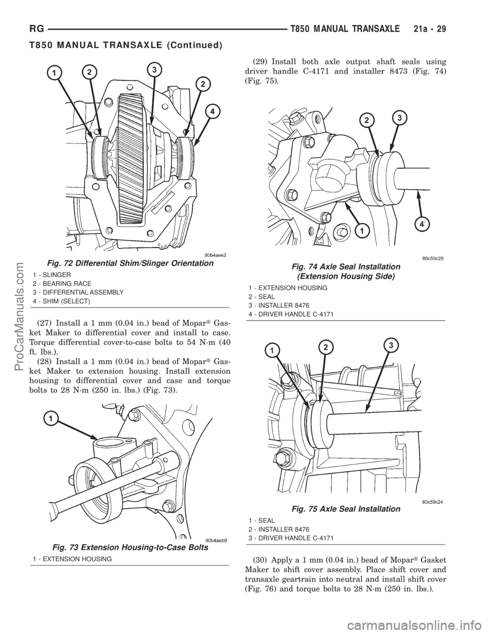
RTV.(26) Install differential assembly with bearing
races and select shim (Fig. 72). Shim selection was
determined before transaxle assembly (Refer to 21 -
TRANSMISSION/TRANSAXLE/MANUAL/DIFFER-
ENTIAL - ADJUSTMENTS).
Fig. 68 Input Bearing Snap Ring
1 - SNAP RING PLIERS
2 - LIFTING BAR 8489
3 - SNAP RING
Fig. 69 End Plate Bolts
1 - BOLT (11)
Fig. 70 Back-Up Lamp Switch
1 - BACK-UP LAMP SWITCH
Fig. 71 Differential Magnet
1 - MAGNET
21a - 28 T850 MANUAL TRANSAXLERG
T850 MANUAL TRANSAXLE (Continued)
ProCarManuals.com
Page 1828 of 2321

(27) Installa1mm(0.04 in.) bead of MopartGas-
ket Maker to differential cover and install to case.
Torque differential cover-to-case bolts to 54 N´m (40
ft. lbs.).
(28) Installa1mm(0.04 in.) bead of MopartGas-
ket Maker to extension housing. Install extension
housing to differential cover and case and torque
bolts to 28 N´m (250 in. lbs.) (Fig. 73).(29) Install both axle output shaft seals using
driver handle C-4171 and installer 8473 (Fig. 74)
(Fig. 75).
(30) Applya1mm(0.04 in.) bead of MopartGasket
Maker to shift cover assembly. Place shift cover and
transaxle geartrain into neutral and install shift cover
(Fig. 76) and torque bolts to 28 N´m (250 in. lbs.).
Fig. 72 Differential Shim/Slinger Orientation
1 - SLINGER
2 - BEARING RACE
3 - DIFFERENTIAL ASSEMBLY
4 - SHIM (SELECT)
Fig. 73 Extension Housing-to-Case Bolts
1 - EXTENSION HOUSING
Fig. 74 Axle Seal Installation
(Extension Housing Side)
1 - EXTENSION HOUSING
2 - SEAL
3 - INSTALLER 8476
4 - DRIVER HANDLE C-4171
Fig. 75 Axle Seal Installation
1 - SEAL
2 - INSTALLER 8476
3 - DRIVER HANDLE C-4171
RGT850 MANUAL TRANSAXLE21a-29
T850 MANUAL TRANSAXLE (Continued)
ProCarManuals.com
Page 1831 of 2321

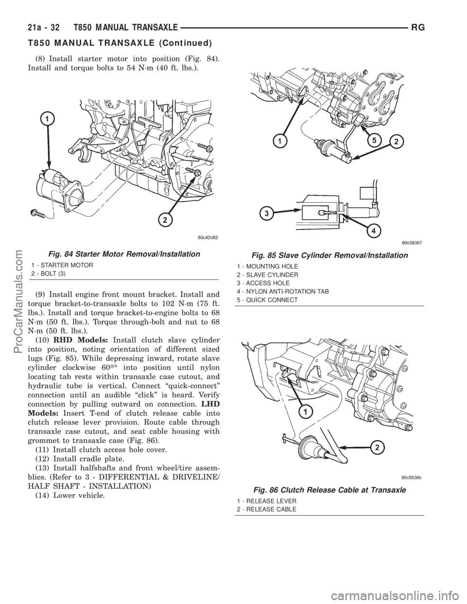
(8) Install starter motor into position (Fig. 84).
Install and torque bolts to 54 N´m (40 ft. lbs.).
(9) Install engine front mount bracket. Install and
torque bracket-to-transaxle bolts to 102 N´m (75 ft.
lbs.). Install and torque bracket-to-engine bolts to 68
N´m (50 ft. lbs.). Torque through-bolt and nut to 68
N´m (50 ft. lbs.).
(10)RHD Models:Install clutch slave cylinder
into position, noting orientation of different sized
lugs (Fig. 85). While depressing inward, rotate slave
cylinder clockwise 60tÉ into position until nylon
locating tab rests within transaxle case cutout, and
hydraulic tube is vertical. Connect ªquick-connectº
connection until an audible ªclickº is heard. Verify
connection by pulling outward on connection.LHD
Models:Insert T-end of clutch release cable into
clutch release lever provision. Route cable through
transaxle case cutout, and seat cable housing with
grommet to transaxle case (Fig. 86).
(11) Install clutch access hole cover.
(12) Install cradle plate.
(13) Install halfshafts and front wheel/tire assem-
blies. (Refer to 3 - DIFFERENTIAL & DRIVELINE/
HALF SHAFT - INSTALLATION)
(14) Lower vehicle.
Fig. 84 Starter Motor Removal/Installation
1 - STARTER MOTOR
2 - BOLT (3)
Fig. 85 Slave Cylinder Removal/Installation
1 - MOUNTING HOLE
2 - SLAVE CYLINDER
3 - ACCESS HOLE
4 - NYLON ANTI-ROTATION TAB
5 - QUICK CONNECT
Fig. 86 Clutch Release Cable at Transaxle
1 - RELEASE LEVER
2 - RELEASE CABLE
21a - 32 T850 MANUAL TRANSAXLERG
T850 MANUAL TRANSAXLE (Continued)
ProCarManuals.com
Page 1834 of 2321

(8) Install engine front mount bracket. Install and
torque bracket-to-transaxle bolts to 102 N´m (75 ft.
lbs.). Install and torque bracket-to-engine bolts to 68
N´m (50 ft. lbs.). Torque through-bolt and nut to 68
N´m (50 ft. lbs.).
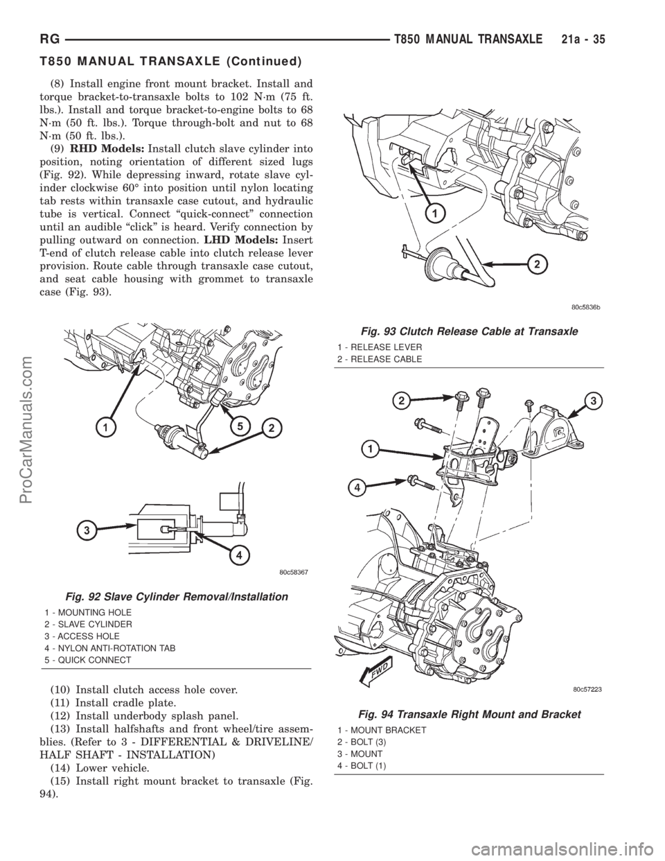
(9)RHD Models:Install clutch slave cylinder into
position, noting orientation of different sized lugs
(Fig. 92). While depressing inward, rotate slave cyl-
inder clockwise 60É into position until nylon locating
tab rests within transaxle case cutout, and hydraulic
tube is vertical. Connect ªquick-connectº connection
until an audible ªclickº is heard. Verify connection by
pulling outward on connection.LHD Models:Insert
T-end of clutch release cable into clutch release lever
provision. Route cable through transaxle case cutout,
and seat cable housing with grommet to transaxle
case (Fig. 93).
(10) Install clutch access hole cover.
(11) Install cradle plate.
(12) Install underbody splash panel.
(13) Install halfshafts and front wheel/tire assem-
blies. (Refer to 3 - DIFFERENTIAL & DRIVELINE/
HALF SHAFT - INSTALLATION)
(14) Lower vehicle.
(15) Install right mount bracket to transaxle (Fig.
94).
Fig. 92 Slave Cylinder Removal/Installation
1 - MOUNTING HOLE
2 - SLAVE CYLINDER
3 - ACCESS HOLE
4 - NYLON ANTI-ROTATION TAB
5 - QUICK CONNECT
Fig. 93 Clutch Release Cable at Transaxle
1 - RELEASE LEVER
2 - RELEASE CABLE
Fig. 94 Transaxle Right Mount and Bracket
1 - MOUNT BRACKET
2 - BOLT (3)
3 - MOUNT
4 - BOLT (1)
RGT850 MANUAL TRANSAXLE21a-35
T850 MANUAL TRANSAXLE (Continued)
ProCarManuals.com