2001 DODGE TOWN AND COUNTRY remote control
[x] Cancel search: remote controlPage 343 of 2321
CD CHANGER
DESCRIPTION
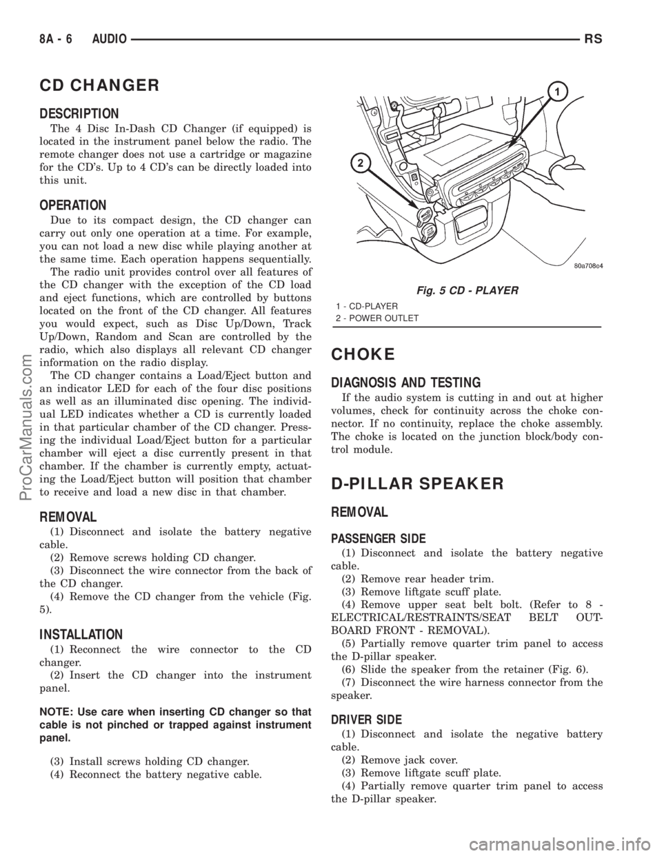
The 4 Disc In-Dash CD Changer (if equipped) is
located in the instrument panel below the radio. The
remote changer does not use a cartridge or magazine
for the CD's. Up to 4 CD's can be directly loaded into
this unit.
OPERATION
Due to its compact design, the CD changer can
carry out only one operation at a time. For example,
you can not load a new disc while playing another at
the same time. Each operation happens sequentially.
The radio unit provides control over all features of
the CD changer with the exception of the CD load
and eject functions, which are controlled by buttons
located on the front of the CD changer. All features
you would expect, such as Disc Up/Down, Track
Up/Down, Random and Scan are controlled by the
radio, which also displays all relevant CD changer
information on the radio display.
The CD changer contains a Load/Eject button and
an indicator LED for each of the four disc positions
as well as an illuminated disc opening. The individ-
ual LED indicates whether a CD is currently loaded
in that particular chamber of the CD changer. Press-
ing the individual Load/Eject button for a particular
chamber will eject a disc currently present in that
chamber. If the chamber is currently empty, actuat-
ing the Load/Eject button will position that chamber
to receive and load a new disc in that chamber.
REMOVAL
(1) Disconnect and isolate the battery negative
cable.
(2) Remove screws holding CD changer.
(3) Disconnect the wire connector from the back of
the CD changer.
(4) Remove the CD changer from the vehicle (Fig.
5).
INSTALLATION
(1) Reconnect the wire connector to the CD
changer.
(2) Insert the CD changer into the instrument
panel.
NOTE: Use care when inserting CD changer so that
cable is not pinched or trapped against instrument
panel.
(3) Install screws holding CD changer.
(4) Reconnect the battery negative cable.
CHOKE
DIAGNOSIS AND TESTING
If the audio system is cutting in and out at higher
volumes, check for continuity across the choke con-
nector. If no continuity, replace the choke assembly.
The choke is located on the junction block/body con-
trol module.
D-PILLAR SPEAKER
REMOVAL
PASSENGER SIDE
(1) Disconnect and isolate the battery negative
cable.
(2) Remove rear header trim.
(3) Remove liftgate scuff plate.
(4) Remove upper seat belt bolt. (Refer to 8 -
ELECTRICAL/RESTRAINTS/SEAT BELT OUT-
BOARD FRONT - REMOVAL).
(5) Partially remove quarter trim panel to access
the D-pillar speaker.
(6) Slide the speaker from the retainer (Fig. 6).
(7) Disconnect the wire harness connector from the
speaker.
DRIVER SIDE
(1) Disconnect and isolate the negative battery
cable.
(2) Remove jack cover.
(3) Remove liftgate scuff plate.
(4) Partially remove quarter trim panel to access
the D-pillar speaker.
Fig. 5 CD - PLAYER
1 - CD-PLAYER
2 - POWER OUTLET
8A - 6 AUDIORS
ProCarManuals.com
Page 347 of 2321
REMOTE SWITCHES
DESCRIPTION
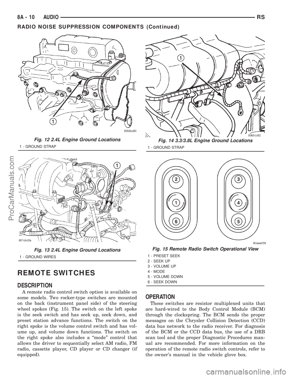
A remote radio control switch option is available on
some models. Two rocker-type switches are mounted
on the back (instrument panel side) of the steering
wheel spokes (Fig. 15). The switch on the left spoke
is the seek switch and has seek up, seek down, and
preset station advance functions. The switch on the
right spoke is the volume control switch and has vol-
ume up, and volume down functions. The switch on
the right spoke also includes a ªmodeº control that
allows the driver to sequentially select AM radio, FM
radio, cassette player, CD player or CD changer (if
equipped).
OPERATION
These switches are resistor multiplexed units that
are hard-wired to the Body Control Module (BCM)
through the clockspring. The BCM sends the proper
messages on the Chrysler Collision Detection (CCD)
data bus network to the radio receiver. For diagnosis
of the BCM or the CCD data bus, the use of a DRB
scan tool and the proper Diagnostic Procedures man-
ual are recommended. For more information on the
operation of the remote radio switch controls, refer to
the owner's manual in the vehicle glove box.
Fig. 12 2.4L Engine Ground Locations
1 - GROUND STRAP
Fig. 13 2.4L Engine Ground Locations
1 - GROUND WIRES
Fig. 14 3.3/3.8L Engine Ground Locations
1 - GROUND STRAP
Fig. 15 Remote Radio Switch Operational View
1 - PRESET SEEK
2 - SEEK UP
3 - VOLUME UP
4 - MODE
5 - VOLUME DOWN
6 - SEEK DOWN
8A - 10 AUDIORS
RADIO NOISE SUPPRESSION COMPONENTS (Continued)
ProCarManuals.com
Page 348 of 2321
DIAGNOSIS AND TESTING
WARNING:
ON VEHICLES EQUIPPED WITH AIRBAGS, REFER
TO ELECTRICAL, RESTRAINTS BEFORE ATTEMPT-
ING ANY STEERING WHEEL, STEERING COLUMN,
OR INSTRUMENT PANEL COMPONENT DIAGNOSIS
OR SERVICE. FAILURE TO TAKE THE PROPER
PRECAUTIONS COULD RESULT IN ACCIDENTAL
AIRBAG DEPLOYMENT AND POSSIBLE PERSONAL
INJURY.
(1) Disconnect and isolate the battery negative
cable. Wait two minutes for the airbag system capac-
itor to discharge before further service.
(2) Remove the remote radio switch(es) from the
steering wheel. (Refer to 8 - ELECTRICAL/AUDIO/
REMOTE SWITCHES - REMOVAL).
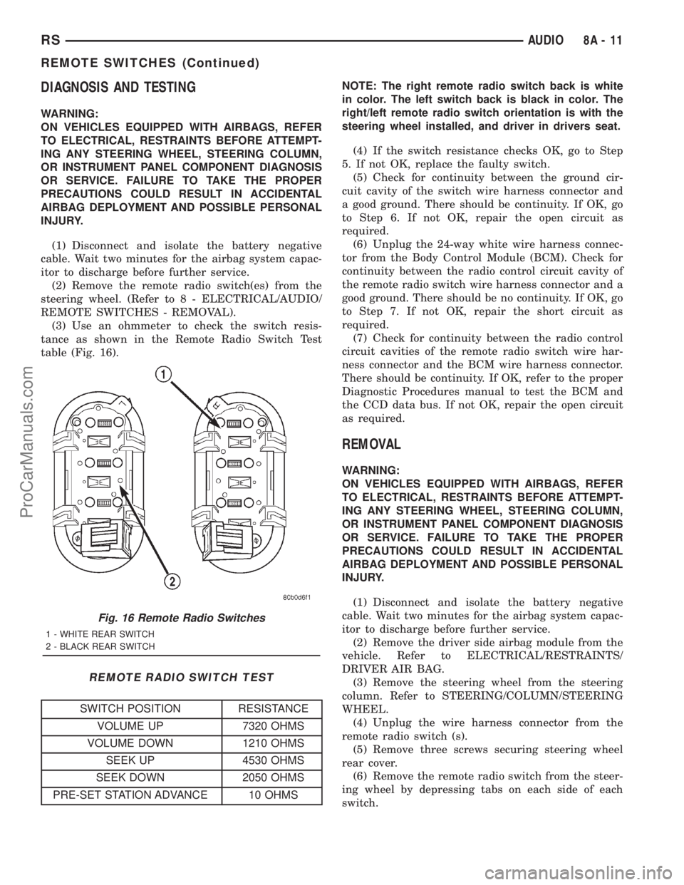
(3) Use an ohmmeter to check the switch resis-
tance as shown in the Remote Radio Switch Test
table (Fig. 16).
REMOTE RADIO SWITCH TEST
SWITCH POSITION RESISTANCE
VOLUME UP 7320 OHMS
VOLUME DOWN 1210 OHMS
SEEK UP 4530 OHMS
SEEK DOWN 2050 OHMS
PRE-SET STATION ADVANCE 10 OHMSNOTE: The right remote radio switch back is white
in color. The left switch back is black in color. The
right/left remote radio switch orientation is with the
steering wheel installed, and driver in drivers seat.
(4) If the switch resistance checks OK, go to Step
5. If not OK, replace the faulty switch.
(5) Check for continuity between the ground cir-
cuit cavity of the switch wire harness connector and
a good ground. There should be continuity. If OK, go
to Step 6. If not OK, repair the open circuit as
required.
(6) Unplug the 24-way white wire harness connec-
tor from the Body Control Module (BCM). Check for
continuity between the radio control circuit cavity of
the remote radio switch wire harness connector and a
good ground. There should be no continuity. If OK, go
to Step 7. If not OK, repair the short circuit as
required.
(7) Check for continuity between the radio control
circuit cavities of the remote radio switch wire har-
ness connector and the BCM wire harness connector.
There should be continuity. If OK, refer to the proper
Diagnostic Procedures manual to test the BCM and
the CCD data bus. If not OK, repair the open circuit
as required.
REMOVAL
WARNING:
ON VEHICLES EQUIPPED WITH AIRBAGS, REFER
TO ELECTRICAL, RESTRAINTS BEFORE ATTEMPT-
ING ANY STEERING WHEEL, STEERING COLUMN,
OR INSTRUMENT PANEL COMPONENT DIAGNOSIS
OR SERVICE. FAILURE TO TAKE THE PROPER
PRECAUTIONS COULD RESULT IN ACCIDENTAL
AIRBAG DEPLOYMENT AND POSSIBLE PERSONAL
INJURY.
(1) Disconnect and isolate the battery negative
cable. Wait two minutes for the airbag system capac-
itor to discharge before further service.
(2) Remove the driver side airbag module from the
vehicle. Refer to ELECTRICAL/RESTRAINTS/
DRIVER AIR BAG.
(3) Remove the steering wheel from the steering
column. Refer to STEERING/COLUMN/STEERING
WHEEL.
(4) Unplug the wire harness connector from the
remote radio switch (s).
(5) Remove three screws securing steering wheel
rear cover.
(6) Remove the remote radio switch from the steer-
ing wheel by depressing tabs on each side of each
switch.
Fig. 16 Remote Radio Switches
1 - WHITE REAR SWITCH
2 - BLACK REAR SWITCH
RSAUDIO8A-11
REMOTE SWITCHES (Continued)
ProCarManuals.com
Page 437 of 2321

²Remote Keyless Entry Module (RKE)- Refer
toRemote Keyless Entry Modulein Power Locks
for more information.
²Electronic Vehicle Information Center
(EVIC)- Refer toElectronic Vehicle Information
Centerin Overhead Console for more information.
²Heated Seat Module (HSM)- Refer toHeated
Seat Modulein Electronic Control Modules for more
information.
²Memory Heated Seat Module (MHSM)-If
the vehicle is equipped with the Memory System,
refer toMemory Seat Mirror Module (MSMM)in
Electronic Control Modules for more information.
Refer toWiring Diagramsfor complete circuit
diagrams. Following are general descriptions of the
major components in the heated seat system.
OPERATION
The heated seat system will only operate when the
ignition switch is in the On position, and the surface
temperature at the front seat heating element sen-
sors is below the designed temperature set points of
the system. The heated seat system will not operate
in ambient temperatures greater than about 41É C
(105É F). The front seat heating elements and sensors
are hard wired to the Heated Seat Module (HSM) or
the Memory Heated Seat Module (MHSM).
The heated seat switches are hard wired to the
Body Control Module (BCM). The BCM monitors the
heated seat switch inputs, then sends heated seat
switch status messages to the HSM or MHSM over
the Programmable Communications Interface J1850
(PCI) data bus. The HSM or MHSM contains the con-
trol logic for the heated seat system. The HSM or
MHSM responds to the heated seat switch status
messages, ignition switch status messages, and the
front seat heating element sensor inputs by control-
ling the output to the front seat heating elements
through integral solid-state relays.
When a seat heater is turned on, the sensor
located on the seat cushion electric heater element
provides the HSM or MHSM with an input indicating
the surface temperature of the seat cushion. If the
surface temperature input is below the temperature
set point for the selected Low or High heated seat
switch position, the HSM or MHSM energizes the
integral solid-state relay, which supplies battery cur-
rent to the heating elements in the seat cushion and
back. When the sensor input indicates the correct
temperature set point has been achieved, the HSM or
MHSM de-energizes the solid-state relay. The HSM
or MHSM will continue to cycle the solid-state relay
as needed to maintain the temperature set point.
The HSM or MHSM and the seat heater elements
operate on non-switched battery current supplied
through the power seat fuse in the intelligent powermodule. However, the HSM or MHSM will automati-
cally turn off the heating elements if it detects an
open in the sensor circuit, a short in the heating ele-
ment circuit causing an excessive current draw, or
when the ignition switch is turned to the Off posi-
tion.
See the owner's manual in the vehicle glove box for
more information on the features, use and operation
of the heated seat system.
DRIVER HEATED SEAT
SWITCH
DESCRIPTION
The heated seat switches are mounted in the
instrument panel center bezel (Fig. 2). The two three-
position rocker-type switches, one switch for each
front seat, are incorporated into one large switch
assembly that also includes the hazzard, rear window
wiper and washer switches. The heated seat switches
provide a resistor multiplexed signal to the Body
Control Module (BCM) through separate hard wired
circuits. Each switch has an Off, Low, and High posi-
tion so that both the driver and the front seat pas-
senger can select a preferred seat heating mode.
Each switch has two Light-Emitting Diodes (LED)
which light to indicate that the heater for the seat is
turned on.
The heated seat switches and their LEDs cannot
be repaired. If either switch or LED is faulty or dam-
aged, the entire switch assembly must be replaced.
Fig. 2 HEATED SEAT SWITCHES
8G - 8 HEATED SEAT SYSTEMRS
HEATED SEAT SYSTEM (Continued)
ProCarManuals.com
Page 511 of 2321
OPERATION
The Compass Mini-Trip Computer (CMTC), Com-
pass Temperature (CT) module in the overhead con-
sole has buttons used to select various functions. The
CMTC, CT selector buttons will not operate until the
ignition is in the RUN position.
When the ignition switch is first turned to the
RUN position the CMTC, CT display;
²Blanks momentarily
²
All segments of the VFD will light for one second
²Blanks momentarily
²Returns to the last mode setting selected before
the ignition was last switched OFF.
DIAGNOSIS & TESTING - COMPASS MINI-TRIP
COMPUTER
Compass Mini-Trip Computer (CMTC) and Com-
pass Temperature (CT) data is obtained from the
Body Control Module (BCM) on the J1850 Data Bus
circuit. The CMTC and CT will display dashes (- -)
for any of the screens it did not receive the bus mes-
sages. The label corresponding to the missing infor-
mation will be lit. If no compass mini-trip computer
data is displayed, check the J1850 Data Bus circuit
communications and the BCM. If the brightness level
is improper check the J1850 Data Bus circuit.
The DRB IIItis recommended for checking the
J1850 Data Bus circuit and the BCM. Perform the
CMTC, CT self diagnosis before replacing the CMTC
or CT module.
REMOVAL
(1) Disconnect and isolate the battery negative
cable.
(2) Remove overhead console. Refer to Overhead
Console Removal and Installation in this section(Re-
fer to 8 - ELECTRICAL/OVERHEAD CONSOLE -
REMOVAL) .
(3) Remove the screws holding Compass Mini-Trip
Computer module in the overhead console.
(4) Remove CMTC module from console assembly.
INSTALLATION
(1) Position the compass mini-trip computer mod-
ule in the overhead console.
(2) Install the ten screws holding the compass
mini-trip computer module in the overhead console.
(3) Install the overhead console. Refer to Overhead
Console Removal and Installation in this section.
(4) Connect the battery negative cable.
NOTE: If a new module has been installed, the com-
pass will have to be calibrated and the variance set.
Refer to Compass Variation Adjustment and Com-
pass Calibration in the Service Procedures section
of this group for the procedures.
UNIVERSAL TRANSMITTER
DESCRIPTION
On some RS models a Homelinkttransceiver is
standard factory-installed equipment. The Homelinkt
transceiver is integral to the Electronic Vehicle Infor-
mation Center (EVIC) and the Compass Mini-Trip
Computer (CMTC), which is located in the overhead
console. The only visible component of the Homelinkt
are the three transmitter push buttons centered
between the modules push buttons located just rear-
ward of the display screen in the overhead console.
The three Homelinkttransmitter push buttons are
identified with one, two or three light indicators so
that they be easily identified by sight or by feel.
Each of the three Homelinkttransmitter push but-
tons controls an independent radio transmitter chan-
nel. Each of these three channels can be trained to
transmit a different radio frequency signal for the
remote operation of garage door openers, motorized
gate openers, home or office lighting, security sys-
tems or just about any other device that can be
equipped with a radio receiver in the 286 to 399
MegaHertz (MHz) frequency range for remote opera-
tion. The Homelinktis capable of operating systems
using either rolling code or non-rolling code technol-
ogy.
The electronics module displays messages and a
small house-shaped icon with one, two or three dots
corresponding to the three transmitter buttons to
indicate the status of the Homelinkt. The EVIC mes-
sages are:
²Cleared Channels- Indicates that all of the
transmitter codes stored in the Homelinkthave been
successfully cleared.
²Training- Indicates that the Homelinktis in
its transmitter learning mode.
²Trained- Indicates that the Homelinkthas
successfully acquired a new transmitter code.
²Transmit- Indicates that a trained Homelinkt
transmitter button has been depressed and that the
Homelinktis transmitting.
The Homelinktcannot be repaired, and is avail-
able for service only as a unit with the EVIC or
CMTC modules. If any of these components is faulty
or damaged, the complete EVIC or CMTC module
must be replaced.
OPERATION
The Homelinktoperates on a non-switched source
of battery current so the unit will remain functional,
regardless of the ignition switch position. For more
information on the features, programming procedures
and operation of the Homelinkt, see the owner's
manual in the vehicle glove box.
8M - 10 OVERHEAD CONSOLERS
COMPASS/MINI-TRIP COMPUTER (Continued)
ProCarManuals.com
Page 553 of 2321
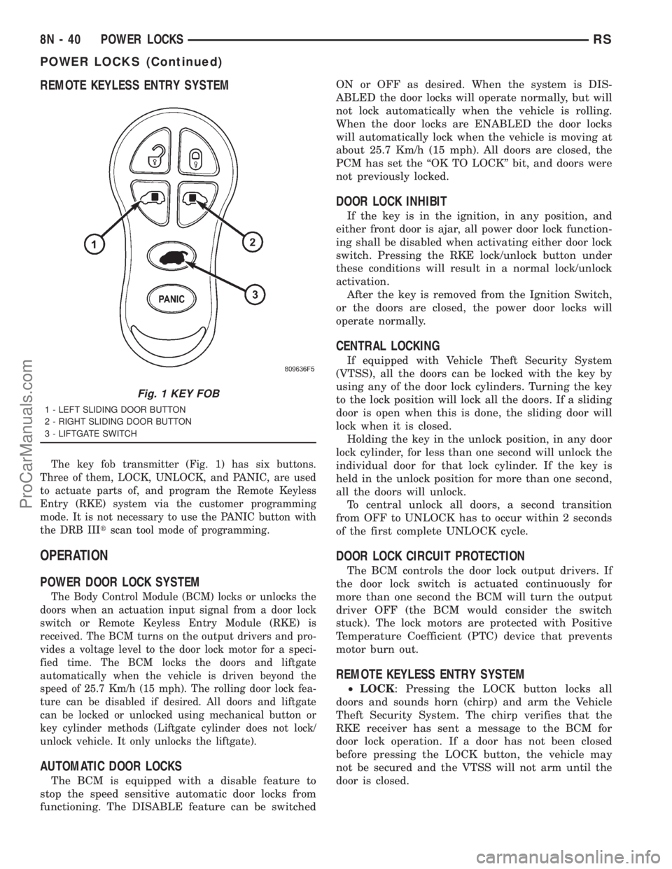
REMOTE KEYLESS ENTRY SYSTEM
The key fob transmitter (Fig. 1) has six buttons.
Three of them, LOCK, UNLOCK, and PANIC, are used
to actuate parts of, and program the Remote Keyless
Entry (RKE) system via the customer programming
mode. It is not necessary to use the PANIC button with
the DRB IIItscan tool mode of programming.
OPERATION
POWER DOOR LOCK SYSTEM
The Body Control Module (BCM) locks or unlocks the
doors when an actuation input signal from a door lock
switch or Remote Keyless Entry Module (RKE) is
received. The BCM turns on the output drivers and pro-
vides a voltage level to the door lock motor for a speci-
fied time. The BCM locks the doors and liftgate
automatically when the vehicle is driven beyond the
speed of 25.7 Km/h (15 mph). The rolling door lock fea-
ture can be disabled if desired. All doors and liftgate
can be locked or unlocked using mechanical button or
key cylinder methods (Liftgate cylinder does not lock/
unlock vehicle. It only unlocks the liftgate).
AUTOMATIC DOOR LOCKS
The BCM is equipped with a disable feature to
stop the speed sensitive automatic door locks from
functioning. The DISABLE feature can be switchedON or OFF as desired. When the system is DIS-
ABLED the door locks will operate normally, but will
not lock automatically when the vehicle is rolling.
When the door locks are ENABLED the door locks
will automatically lock when the vehicle is moving at
about 25.7 Km/h (15 mph). All doors are closed, the
PCM has set the ªOK TO LOCKº bit, and doors were
not previously locked.
DOOR LOCK INHIBIT
If the key is in the ignition, in any position, and
either front door is ajar, all power door lock function-
ing shall be disabled when activating either door lock
switch. Pressing the RKE lock/unlock button under
these conditions will result in a normal lock/unlock
activation.
After the key is removed from the Ignition Switch,
or the doors are closed, the power door locks will
operate normally.
CENTRAL LOCKING
If equipped with Vehicle Theft Security System
(VTSS), all the doors can be locked with the key by
using any of the door lock cylinders. Turning the key
to the lock position will lock all the doors. If a sliding
door is open when this is done, the sliding door will
lock when it is closed.
Holding the key in the unlock position, in any door
lock cylinder, for less than one second will unlock the
individual door for that lock cylinder. If the key is
held in the unlock position for more than one second,
all the doors will unlock.
To central unlock all doors, a second transition
from OFF to UNLOCK has to occur within 2 seconds
of the first complete UNLOCK cycle.
DOOR LOCK CIRCUIT PROTECTION
The BCM controls the door lock output drivers. If
the door lock switch is actuated continuously for
more than one second the BCM will turn the output
driver OFF (the BCM would consider the switch
stuck). The lock motors are protected with Positive
Temperature Coefficient (PTC) device that prevents
motor burn out.
REMOTE KEYLESS ENTRY SYSTEM
²LOCK: Pressing the LOCK button locks all
doors and sounds horn (chirp) and arm the Vehicle
Theft Security System. The chirp verifies that the
RKE receiver has sent a message to the BCM for
door lock operation. If a door has not been closed
before pressing the LOCK button, the vehicle may
not be secured and the VTSS will not arm until the
door is closed.
Fig. 1 KEY FOB
1 - LEFT SLIDING DOOR BUTTON
2 - RIGHT SLIDING DOOR BUTTON
3 - LIFTGATE SWITCH
8N - 40 POWER LOCKSRS
POWER LOCKS (Continued)
ProCarManuals.com
Page 557 of 2321
INSTALLATION
(1) Position the RKE module and install the
screws.
(2) Connect the wire connector to the RKE module
(Fig. 4).
(3) Install the instrument panel top pad.
(4) Connect the battery negative cable.
SLIDING DOOR LOCK MOTOR
REMOVAL
(1) Disconnect and isolate the negative battery
cable.
(2) Remove sliding door trim panel (Refer to 23 -
BODY/DOORS - SLIDING/TRIM PANEL - REMOV-
AL).
(3) Remove sound pad as necessary.
(4) Remove latch/lock control cover.
(5) Remove latch/lock control.
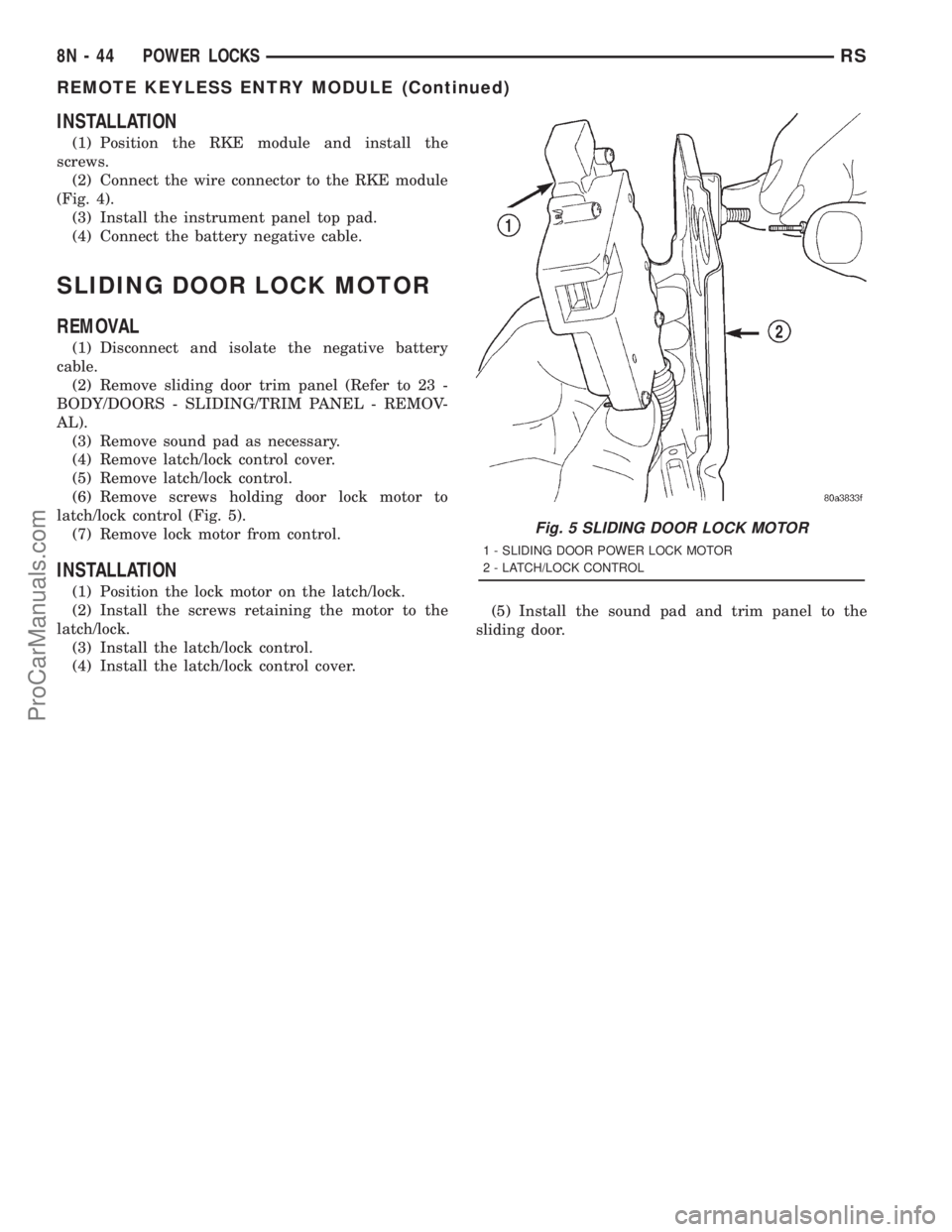
(6) Remove screws holding door lock motor to
latch/lock control (Fig. 5).
(7) Remove lock motor from control.
INSTALLATION
(1) Position the lock motor on the latch/lock.
(2) Install the screws retaining the motor to the
latch/lock.
(3) Install the latch/lock control.
(4) Install the latch/lock control cover.(5) Install the sound pad and trim panel to the
sliding door.
Fig. 5 SLIDING DOOR LOCK MOTOR
1 - SLIDING DOOR POWER LOCK MOTOR
2 - LATCH/LOCK CONTROL
8N - 44 POWER LOCKSRS
REMOTE KEYLESS ENTRY MODULE (Continued)
ProCarManuals.com
Page 558 of 2321

POWER MIRRORS
TABLE OF CONTENTS
page page
POWER MIRRORS
DESCRIPTION...........................45
OPERATION.............................45
DIAGNOSIS AND TESTING.................45
POWER MIRRORS......................45
AUTOMATIC DAY / NIGHT MIRROR
DESCRIPTION...........................46
OPERATION.............................46
DIAGNOSIS AND TESTING.................47AUTOMATIC DAY/NIGHT MIRROR..........47
REMOTE SWITCH
DIAGNOSIS AND TESTING.................48
REMOTE SWITCH......................48
REMOVAL..............................48
INSTALLATION...........................48
SIDEVIEW MIRROR
REMOVAL..............................48
POWER MIRRORS
DESCRIPTION
If equipped with power mirrors, the control switch
is located on the instrument panel to the left of the
headlamp switch.
OPERATION
The power mirrors are connected to battery feed at
all times. Each mirror head contains two electric
motors, two drive mechanisms, an electric heating
element, and the mirror glass. If the vehicle is
equipped with the optional memory system, each
mirror head also contains both a horizontal and a
vertical motor position sensor. One motor and drive
controls mirror up-and-down movement, and the
other controls right-and-left movement.
An optional driver side outside electrochromic mir-
ror is able to automatically change its reflectance
level. This mirror is controlled by the circuitry of the
automatic day/night inside rear view mirror. A thin
layer of electrochromic material between two pieces
of conductive glass make up the face of the mirror.
Two photocell sensors on the inside rear view mirror
are used to monitor light levels and adjust the reflec-tance of both the inside and driver side outside mir-
rors. This change in reflectance helps to reduce the
glare of headlamps approaching the vehicle from the
rear. (Refer to 8 - ELECTRICAL/POWER MIRRORS/
AUTOMATIC DAY / NIGHT MIRROR - DESCRIP-
TION) for more information on this system.
The motors which operate the mirrors are part of
the mirror assembly and cannot be serviced sepa-
rately.
DIAGNOSIS AND TESTING - POWER MIRRORS
(1) Remove Power Mirror Switch. (Refer to 8 -
ELECTRICAL/POWER MIRRORS/POWER MIRROR
SWITCH - REMOVAL).
(2) Disconnect wiring harness connector to the
power mirror switch and headlamp switch.
(3) Using two jumper wires:
²Connect one to a 12-volt source
²Connect the other to a good body ground
²Refer to the Mirror Test Chart for wire hookups
at the switch connector (Fig. 1).
(4) If results shown in table are not obtained,
check for broken or shorted circuit, or replace mirror
assembly as necessary.
RSPOWER MIRRORS8N-45
ProCarManuals.com