Page 53 of 64

ZKE - 53
DRIVER’S SEAT MEMORY FUNCTION
As with previous systems, the seat memory feature of the SM stores three seat positions
for recall. The positions are stored in a non-volatile memory preventing loss of positions if
in case the SM or the battery is disconnected.
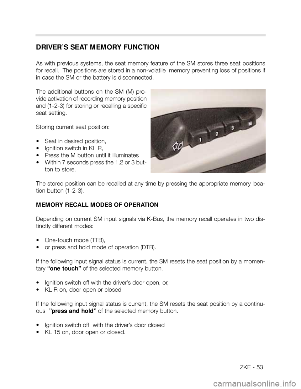
The additional buttons on the SM (M) pro-
vide activation of recording memory position
and (1-2-3) for storing or recalling a specific
seat setting.
Storing current seat position:
• Seat in desired position,
• Ignition switch in KL R,
• Press the M button until it illuminates
• Within 7 seconds press the 1,2 or 3 but-
ton to store.
The stored position can be recalled at any time by pressing the appropriate memory loca-
tion button (1-2-3).
MEMORY RECALL MODES OF OPERATION
Depending on current SM input signals via K-Bus, the memory recall operates in two dis-
tinctly different modes:
• One-touch mode (TTB),
• or press and hold mode of operation (DTB).
If the following input signal status is current, the SM resets the seat position by a momen-
tary“one touch”of the selected memory button.
• Ignition switch off with the driver’s door open, or,
• KL R on, door open or closed
If the following input signal status is current, the SM resets the seat position by a continu-
ous ”press and hold”of the selected memory button.
• Ignition switch off with the driver’s door closed
• KL 15 on, door open or closed.
Page 57 of 64

SEAT OPERATION
Each motor for seat adjustment contains a micro-processor (called a Ripple Counter) that
receives a digital signal from the seat control module for motor activation. The motors are
connected to KL 30 and KL 31 and respond to the signals generated by the seat module
when seat movement is requested. The seat adjustment switch provides ground input sig-
nals to the module when seat movement is desired. The module processes these input sig-
nals and sends output signals to the seat motor processors. The seat motor processors
activate the motors and the seat moves to the desired point.
The circuitry of the Ripple Counter detects the motor activation current. As the armature
segments of the motor rotate passed the brushes, the current flow rises and falls produc-
ing a ripple effect. The peaks of these ripples are counted and stored in the Ripple Counter
module. The memory function of the seat module uses this ripple count instead of feed-
back potentiometers to memorize and recall seat positions.
RIPPLE COUNT RECOGNITION
When the seat is installed and the battery is connected, the ripple counter uses the initial
position of the motors as the “Zero Position”. Any movement from this point is counted as
“+” or “-” pulses as the motors move in either direction. The pulse position of the motors
is stored in the seat module, in an EEPROM, before the ZKE goes into its “Sleep Mode”.
This prevents the position recognition from being lost. If the battery is disconnected before
the 16 minute sleep mode activation, the memory positions of the seat will be lost and
reprogramming will be required.
ZKE -57
Page 62 of 64

62
SLEEP MODE
To lower the constant battery draw when the vehicle is parked, The complete ZKE system
will go into the “Sleep Mode” 16 minutes after the ignition has been switched off and no
further ZKE function is active.
Approximate X5 Battery draw: • Ignition switch off = approx 750 mA.
• One minute after = approx. 560 mA.
• After 16 minutes (sleep mode) = approx. 18 mA.
All modules in the ZKE system will go into the sleep mode. The P-Bus remains active, how-
ever no data transfer takes place until a wake-up request is received. The general module,
door modules or keyless remote module can wake the system up and put the ZKE back
on line. The K-Bus is not active in the sleep mode, however the GM III of Remote Entry
Module can put the K-Bus back on-line with a wake-up request.
SLEEP MODE CRITERIA: KL R, 15 OFF and no further function activated for 16 minutes.
WAKE UP CRITERIA: KL R or 15 “ON” or a change in one of the signal states listed below.
SIGNAL ACTIVITY ORIGINATING
MODULE
K-BUS High General Module
Door jamb switches (possibility of 4) Low “
Trunk lid lock cylinder microswitch High “
Trunk lid pushbutton microswitch Low “
Interior Trunk lid pushbutton microswitch Low “
Central locking button Low “
Hood microswitch Low “
Trunk Lid microswitch Low “
Interior light switch Low “
FIS sensor Low “
Tilt Alarm sensor Low “
FBZV operational signal High FBZV Module
Driver’s door lock microswitch - (lock) High PM-FT/SB
““““ - (unlock) High “
Passenger door lock microswitch - (lock) High PM-BT
““““ - (unlock) High “
Tailgate
Tailgate
Tailgate
Tailgate
UIS