Page 68 of 1002
Downloaded from www.Manualslib.com manuals search engine
Engine-General
This section covers system descriptions and general informa-
tion on engines and engine management systems. Also cov-
ered is basic engine troubleshooting.
For specific repair procedures, refer to the appropriate repair
group:
110 Engine Removal and Installation
0 113 Cylinder Head Removal and Installation
116 Cylinder Head and Valvetrain
0 117 Camshaft Timing Chain
119 Lubrication System
120 Ignition System
130 Fuel Injection
0 170 Radiator and Cooling System
E39 models are fitted with a variant of either an inline 6-cylin-
der or a
V-8 engine. See Table a.
Table a. Engine specifications
Page 71 of 1002

Downloaded from www.Manualslib.com manuals search engine
Two common causes of driveability problems are incorrect
system voltage and bad grounds.
System voltage
Digital motor electronics (DME) requires that the system (bat-
tery) voltage be maintained within a narrow range of DC volt-
age.
DC voltage levels beyond or below the operating range,
or any
AIC voltage in the electrical system can cause havoc.
When troubleshooting an illuminated MIL, make sure the bat-
tery is fully charged and capable of delivering all its power to
the electrical system. An undercharged battery can amplify
AIC alternator output ripple.
To
make a quick check of the battery charge, measure the
voltage across the battery terminals with all cables attached
and the ignition off.
Afully charged battery will measure 12.6
volts or slightly more, compared to 12.1 5 volts for a battery
with a 25% charge.
The DME system operates at low voltage and current levels,
making it sensitive to small increases in resistance. The elec-
trical system is routinely subjected to corrosion, vibration and
wear, so faults or corrosion in the wiring harness and connec-
tors are not uncommon. Check the battery terminals
forcorro-
sion or loose cable connections. See 121 Battery, Starter,
Alternator for additional information.
If a battery cable connection has no
v~sible faults but is still
suspect, measure the voltage drop across the connection. A
large drop indicates excessive resistance, meaning that the
connection is corroded, dirty, or damaged. Clean or repairthe
connection and retest.
NOTE-
For instructions on conducting a voltage drop test and other
general electrical troubleshooting information, see
600 Elec-
trical System-General.
Visually inspect all wiring, connectors, switches and fuses in
the system. Loose or damaged connectors can cause inter-
mittent problems, especially the small terminals in the ECM
connectors. Disconnect the wiring harness connectors to
check for corrosion, and use electrical cleaning spray to re-
move contaminants.
Main grounds
Good grounds are critical to proper DME operation. If a
ground connection has no visible faults but is still suspect.
measure the voltage drop across the connection. A large volt-
age drop means high resistance. Clean or repair the connec-
tion and retest.
LBuntr.yP~sbhnllcn.can#-AII A,~iltl Rcsrwsd
Page 72 of 1002
Downloaded from www.Manualslib.com manuals search engine
100-6
( Engine-General
The main grounds for the fuel and ignition circuits of the DME
system are illustrated below; see 610 Electrical Component
Locations for additional ground and component locations.
4 Ground for engine management system in right rear of en-
gine compartment on E-box bulkhead (arrow).
6-cylinder models: Grounds
for ignition coils (arrows)
4 V-8 models: Grounds for ignition coils, at cylinders 3
(arrow) and 7.
4 Fuel pump ground (arrow) below right tail light in luggage
compartment.
NOTE-
Ground location for sedan shown, wagon models may
differ.
Page 100 of 1002

Downloaded from www.Manualslib.com manuals search engine
11 3-6
Cylinder Head Removal and Installation
- Disable ignition system by removing DME main relay. See
610 Component Locations for relay location.
WARNING-
. The ignition system produces high voltages that can be fa-
tal. Avoid contact with exposed terminals and use
exfreme
caution when working on a car with the ignition switched on
or the engine running.
Do not touch or disconnect ignition
components while
the engine is running or being cranked by the starter.
Failure to remove the DME main relay or attempting to
disa-
bie the fuel andignition systems by other methods may result
in damaoe to the enoine control module
(ECM).
- - Remove plastic cylinder head cover(s)
,,I . ,. .*,.,,&- - Remove coil grounding straps.
I CAUTION-
I nition system components. I
- Remove coils.
- Remove spark plugs from all cylinders.
NOTE-
Check the spark plugs for oil deposits that may indicate poor
cylinder sealing, then set them aside in order. Used spark
plugs should be reinstalled in the same cylinder from which
they were removed.
4 Install compression gauge in first cylinder spark plug hole,
tight enough to form a good seal.
- With parking brake set, transmission in PARK or NEUTRAL,
and accelerator pedal pressed to floor, crank engine with
starter. Record highest value indicated by gauge.
NOTE-
* The compression gauge reading should increase with
each compression stroke and reach near its maximum
reading in about
4-6 strokes.
All cylinders should reach maximum compression in the
same number of
strolces. If a cylinder needs significantly
more strokes to reach
maximum compression, there is a
problem.
Page 101 of 1002

Downloaded from www.Manualslib.com manuals search engine
. .- . --
Lr -- - - - -- Cylinder Head Removal and Installation I -
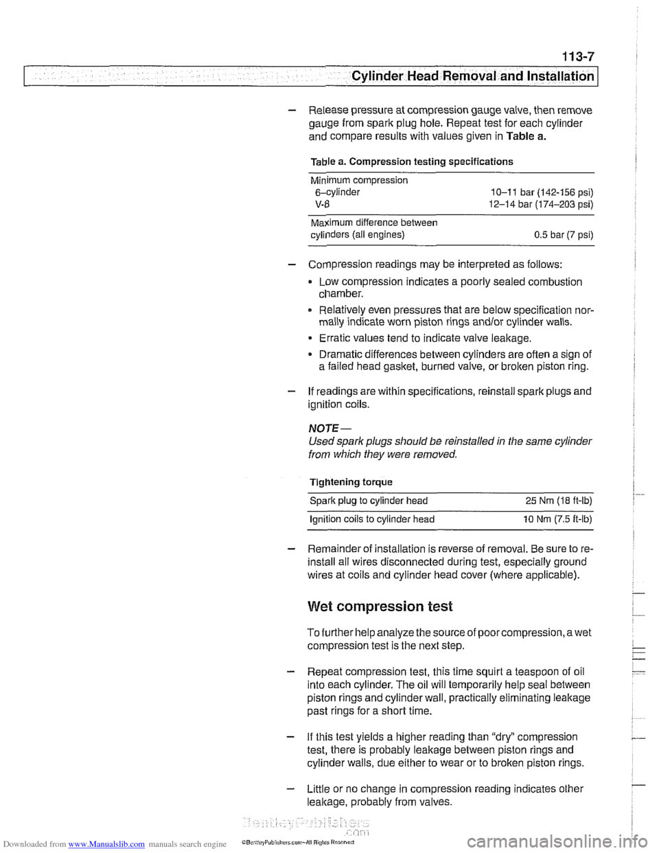
- Release pressure at compression gauge valve, then remove
gauge from spark plug hole. Repeat test for each cylinder
and compare results with values given in Table a.
Table a. Compression testing specifications
Minimum compression
6-cylinder
10-1 1 bar (142-156 psi)
V-8 12-14 bar (174-203 psi)
Maximum difference between
cylinders (all engines)
0.5 bar (7 psi)
- Compression readings may be interpreted as follows:
Low compression indicates a poorly sealed combustion
chamber.
0 Relatively even pressures that are below specification nor-
mally indicate worn piston rings
andlor cylinder walls.
Erratic values tend to indicate valve leakage.
Dramatic differences between cylinders are often a sign of
a failed head
gasket, burned valve, or broken piston ring.
- If readings are within specifications, reinstall spark plugs and
ignition coils.
NOTE-
Used spark plugs should be reinstalled in the same cylinder
from which they were removed.
Tightening torque Spark plug to cylinder head 25 Nm
(18 ft-lb)
lanition coils to cylinder head 10 Nm (7.5 ft-lb)
- Remainder of installation is reverse of removal. Be sure to re-
install all wires disconnected during test, especially ground
wires at coils and cylinder head cover (where applicable).
Wet compression test
To further help analyze the source of poorcompression,awet
compression test is the next step.
- Repeat compression test, this time squirt a teaspoon of oil
into each cylinder. The oil will temporarily help seal between
piston rings and cylinder wall, practically eliminating leakage
past rings for a short time.
- If this test yields a higher reading than "dry" compression
test, there is probably leakage between piston rings and
cylinder walls, due either to wear or to broken piston rings.
- Little or no change in compression reading indicates other
leakage, probably from valves.
Page 106 of 1002
Downloaded from www.Manualslib.com manuals search engine
-
Cylinder Head Removal and Installation c
q Remove secondary air inject~on check valve (arrow).
4 Remove cylinder head top cover:
Remove plastic trim caps (arrows).
Remove engine oil filler cap.
Remove cover hold down fasteners and lift off cover.
4 Remove ignition coils:
Disconnect ignition coil harness connectors.
. Remove coil mounting fasteners.
Remove coils.
Remove ground straps.
NOTE-
Make note of ground wire at mounting studs arrangement
during removal.
- Remove sparlc plugs.
- Remove cylinder head cover mounting fasteners and remove
cylinder head cover.
NOTE-
The cylinder head cover mounting bolt insulators and gas-
lets should be reinstalled in their original locations. Make
note of their arrangement during removal.
Page 123 of 1002

Downloaded from www.Manualslib.com manuals search engine
Cylinder Head Removal and Installation
4 If applicable, remove secondary air injection pump:
Disconnect hose at one-way valve
(A).
Remove bolts at support bracket on strut tower (arrows).
Disconnect electrical harness from bottom of secondary
air injection pump.
Remove mounting bracket from strut tower.
4 Remove ignition coils:
* Disconnect ignition coil harness connectors.
Remove coil mounting fasteners.
Remove coils.
* Remove ground straps.
CA UTIOI\C
Note location of all ground wires. Failure to reinstall grounds
can result in permanent damage to engine control module or
ignition system components.
Set coil harness to side of engine compartment
- Remove cylinder head cover mounting fasteners and remove
cylinder head cover.
NOTE-
The cylinder head cover mounting bolt insulators and gas-
ltets should be reinstalled in their original locations. Male
note of their arrangement during removal.
- Remove spark plugs
4 Remove oil baffle cover from above intake camshaft.
Page 152 of 1002
Downloaded from www.Manualslib.com manuals search engine
Cylinder Head Removal and Installation
Pry out ignition coil cover trim caps,
covers from lefl and right sides. remove fasteners
and
< Disconnect throttle cables from throttle shafl (A) and remove
cables from support bracket
(B).
< Disconnect cable from jump start post (arrow) on left cylinder
head cover.