2001 BMW 530i DSC
[x] Cancel search: DSCPage 75 of 1002

Downloaded from www.Manualslib.com manuals search engine
110-3
Engine Removal and lnstallationl
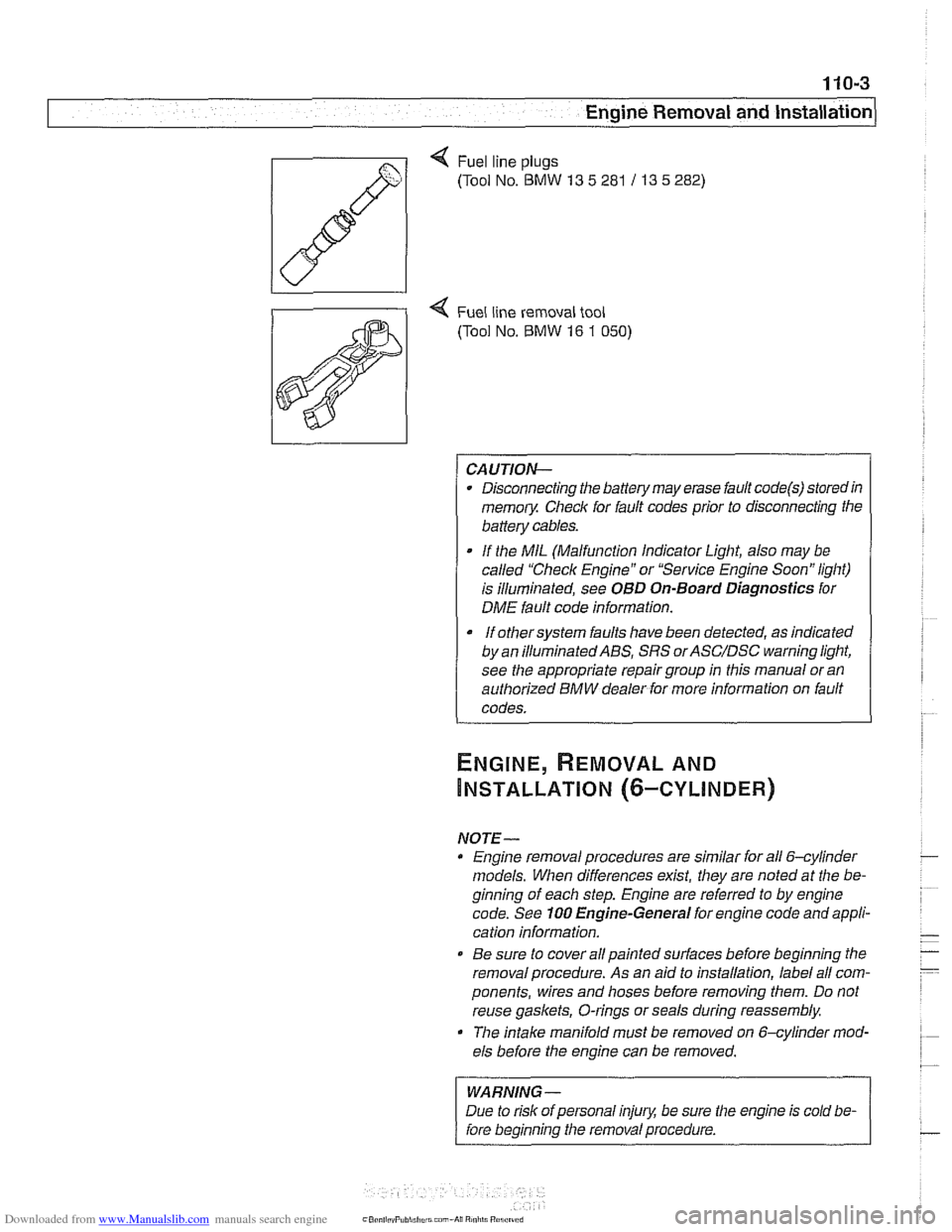
Q Fuel line plugs
(Tool No.
BMW 13 5 281 / 13 5 282)
4 Fuel line removal tool
(Tool No.
BMW 16 1 050)
CAUTION-
Disconnecting the battery may erase fault code@) storedin
memoiy Check for fault codes prior to disconnecting the
battery cables.
If the MIL (Malfunction Indicator Light, also may be
called "Check Engine" or "Service Engine Soon" light)
is illuminated, see
OBD On-Board Diagnostics for
DME fault code information.
It orhersysrem faults have been detected, as indicated I
by an ~llum~nated ABS, SRS orASC/DSC ~arning light,
see the appropriate repair group in this manual or an
authorized BMW dealer for more information on fault
codes.
NOTE- Engine removal procedures are similar for all 6-cylinder
models. When differences
exist, they are noted at the be-
ginning of each step. Engine are referred to by engine
code. See
100 Engine-General for engine code and appli-
cation information.
@ Be sure to cover all painted surfaces before beginning the
removal procedure. As an aid to installation, label all com-
ponents, wires and hoses before removing them. Do not
reuse
gaskets, O-rings or seals during reassembly.
The
intake manifold must be removed on &cylinder mod-
els before the engine can be removed.
WARNING-
Due to risk of personal injury, be sure the engine is cold be-
fore beginning the removal procedure.
Page 414 of 1002

Downloaded from www.Manualslib.com manuals search engine
Fuel Injection
- Ignition:
Direct ignition
Knock control
4 Primary1 secondary ignition monitoring
- Emissions:
OBD II compliance
Secondary air injection
Pre- and post-catalyst oxygen sensors
0 Electrically heated DME-mapped thermostat
Misfire detection
Evaporative emission control and
leak detection
Malfunction indicator light (MIL)
Performance controls:
Dual VANOS control
Output of injection signal (TI) for fuel economy gauge
Output of engine rpm (TD) for tachometer
AIC compressor control
0 Electric radiator cooling fan
CAN-Bus communication
Stability and traction system
(ABSIASCIDSC) interlace
Electronic immobilizer (EWS)
Cruise control
ECM programming
Page 447 of 1002

Downloaded from www.Manualslib.com manuals search engine
Fuel Injection
Intake air temperature
([AT) sensor,
testing and replacing
Disconnect harness connector from intake air temperature
sensor
(A) at air filter housing.
Turn ignition on. Using a digital voltmeter, check for
5 volts
between supply voltage wire in connector and ground.
If volt-
age is not present, test ECM
inputs/outputs as described lat-
er.
With harness connector disconnected, test resistance across
sensor terminals. If any faults are found, replace IAT sensor.
IAT test resistance
0 lV *lac (50" i-2°F) 7-1 1.6 k.0.
020' kl°C (68' 322°F) 2.1-2.9 it.0.
080" ?lac (176" i-2°F) 0.27-0.40 itn
Auxiliary throttle valve (ADS)
(M62 and M62 TU engine), replacing
ADS components 540i models with ASC and DSC are fitted with a motor-driv-
en auxiliary throttle valve and housing ahead of the standard Throttle position switch throttle housing. The ADS throttle valve controls engine throt-
tle intervention based on signals from the DME control mod-
ule if road conditions, such as slipping driven wheel, warrant
reduced engine power.
ADS throttle housing
Bowden cable NOTE-
Before replacing the ADS throttle housing, read DME fault
ADS lhroltle actualor codes.
- ADS throttle housing replacement:
Switch off ignition and disconnect electrical connector on
ADS throttle body.
Remove hose from idle control valve.
Loosen hose clamps and remove throttle housing air in-
take boot.
Disconnect cable from ADS throttle body.
- Unscrew 3 bolts and remove ADS throttle body.
Installation is reverse of removal.
- Adjust cable so that no free play is present.
Page 454 of 1002

Downloaded from www.Manualslib.com manuals search engine
-
Fuel Injection
Table e. Bosch 5.2.1 ECM pin assignments
Pin
I~iqnal 1 Description 1 Note
I I I
46 llnput ICrankshaft position sensor Icrankshaft positionlrpm sensor
38
39
40
41
42
43
44
45 Ground Input
Output
Output
Output
Output
Ground
47
48
49
50
51
Not used
I Not used
52
Shield, knock sensor
Oil level
- thermal
Injection signal
injection signal
Idle speed control - opening winding
Idle speed control - closing winding
Not used
Ground
Ground
-- Ground Input
Ground
Ground Not used Knock sensor
Oil level sensor
Cylinder
4 fuel injector
valve
Cylinder
1 fuel injector valve
Idle speed control valve
Idle speed control valve
Shield, crankshaft sensor
5
6
7
12 Not used
Ground
Intake air temperature sensor
Connector
X60004
8
9 10
11
14 1 1 Not used I
Shield, knock sensor
Shield, sensor
I
Shield, sensor 3
Shield, itnock sensor
Input
- Knoclc sensor
Knock sensor
Knock sensor
Knock sensor
Instrument cluster
Output
2 llnput l~erminal 30 voltage supply /Megrated instrument cluster control module (IKE)
Alt. charge indicator signal, terminal 61 1
Not used
Start signal terminal
50
Not used
15
16
17
18
Output
Ignition switch
Not used
Not used
Activation of relay for fuel pump
Not used
19
Fuel pump relay
Output Not used
I I I 20 loutput ICARB signal /Data link connector
Not
used
Not used
Engine speed signal output (TD)
Not used
Light module
21
Cruise control module (Tempomat)
22 llnput I Right rear wheel speed signal /ABS/ASC or ABSIDSC control module
Oulput
Washer
fluid level,
brake fluid level
Page 457 of 1002

Downloaded from www.Manualslib.com manuals search engine
130-67
Fuel Injection /
ME 7.2 system overview
The Bosch ME 7.2 system is used on 1999 - 2002 540i mod-
els.
1 4 The ME 7.2 enaine control module (ECM). located on the
l and a combined total of 134 pins.
--__-- 1 I. 9 pin connector
12 3 4 5 2 24 pin connector
0lliC;nii, 3. 52 pin connector
4. 40 pin connector
5. 9 pin connector
The ME 7.2 system has the following functions or capabilities:
Electronic throttle control (EDK) integrates idle and cruise
control functions. ECM carries out all throttle and idle con-
trol functions directly via EDK system.
Leak diagnosis pump
(LDP) control and feedback monitor-
ing for evaporative system leak testing.
Batterylalternator charge logic (idle speed varies with bat-
tery state of charge).
CAN-Bus communications with instrument cluster.
EWS
111 (3.3) "rolling code" ISN interface.
Ignition
knock sensors.
DSC (dynamic stability control) torque reduction.
Monitoring and control of VANOS
(camshaft timing) with
active Hail sensor for camshaft position monitoring.
Integrated altitude sensor.
One touch engine start control
Single speed secondary air injection system.
Long life spark plugs.
IHKA auxiliary (electric) cooling fan control.
All emissions-related ME 7.2 electrical components are mon-
itored for faults. if driveability complaints are encountered or
the malfunction indicator
light (MIL) is illuminated, interrogate
fault memory using a compatible scan tool.
4 Use a break-out box for ME 7.2 system testing and diagnosis
at the control module
(break out box set: BMW special tool
90
88 6 121 300).
Electrically heated (characteristic
map) cooling system
DME Harness Connector thermostat.
Page 469 of 1002

Downloaded from www.Manualslib.com manuals search engine
Fuel Injection I
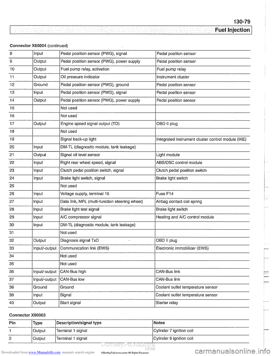
Connector X60004 (continued)
8 10
11
12
13
14
15
16
9
Output 0
Input
17
18
19
20
21
22
23
24
25
26
27
28
29
30
31
32
33
34
35
36
39
llnput lsignal l~oolant outlet temperature sensor
Output
Output
Ground
Input
Output
I I - I
40 /output Istart signal Istarter relay
Pedal position sensor (PWG), signal
Output Input
Output
input
Input
Input
Input
Input
Input
input
Input
Output
Input/-output
Input/-output
37
Connector X60003
Pedal position sensor
Fuel pump relay, activation
Oil pressure indicator Pedal position sensor (PWG), ground
Pedal position sensor (PWG), signal
Pedal position sensor (PWG), power supply
Not used
Not used Fuel
pump relay
Instrument cluster
Pedal position sensor
Pedal position sensor
Pedal position sensor
Engine speed signal output (TD)
Not used
Signal
back-up light
DM-TL (diagnostic module,
tank leakage)
Signal oil level sensor
Right rear wheel speed, signal
Clutch pedal position switch, signal
Brake light switch, signal
Not used
Voltage supply, terminal
15
Data link, MFL (multi-function steering wheel)
Brake light test signal
AJC compressor signal
DM-TL (diagnostic module, tank
leakage)
Not used
Diagnosis signal
TxD
Communication link (EWS)
Not used
Not used
CAN-BUS hiqh
38 1 Ground l~round I Coolant outlet temperature sensor
OED II plug
Integrated instrument cluster control module (IKE)
Light module
ABSIDSC control module
Clutch pedal position switch
Brake light switch
Fuse
F14
Airbag contact coil spring
Brake light switch
Heating and
A/C control module
OBD
II plug
Electronic immobilizer (EWS)
CAN-Bus link
CAN-Bus link
Input/-output CAN-Bus low
Page 621 of 1002

Downloaded from www.Manualslib.com manuals search engine
300 Suspension. Steering and Brakes .
Genera8
General ........................... .30 0.2
Aluminum suspension components
...... .30 0.2
Front Suspension ................. .30 0.2
Front suspension 6-cylinder models
(525i.5281. 530i) ..................... .30 0.3
Front suspension V-8 models (540i) ...... .30 0.4
Rear Suspension .................. .30 0.5
Sedan models
....................... .30 0.5
Rear suspension sedan models ........ .30 0.6
Sport Wagon models ................. .30 0.6
Rear suspension Sport Wagon
(with coil springs)
.................... .30 0.7
Rear suspension Sport Wagon
(EHC with air springs)
................. .30 0.8
EHC operational diagram .............. .30 0.9
Steering ......................... .30 0.10
Rack-and-pinion steering ............. .30 0.10
Recirculating ball and nut steering ...... .30 0.10
..................... Brake System 300-10
Wheels and Tires ................. 300-1 1
............... Rim and tire sizes table 300-1 1
Electronic Brake and Stability
.................. Control Systems 300-1 1
E39 electronic brake and stability
........ control systems application table 300-12
........................ ABS system 300-1 2
Automatic Stability Control (ASC)
....... 300-12
ABSIASC traction control system ....... 300-13
Dynamic Stability Control (DSC)
........ 300-14
Ride Height ....................... 300-14
......... Front ride height specifications 300-1 5
......... Rear ride height specifications 300-16
Page 622 of 1002

Downloaded from www.Manualslib.com manuals search engine
[~us~ension, Steering and Brakes - General
This section of the manual covers front and rear suspension,
braking and steering systems, and contains wheel, tire and
wheel alignment information and specifications. Also covered
here are the integrated braking and suspension systems in-
cluding
antilock braking (ABS), traction control (ASCIDSC),
and electronic height control (EHC).
Vehicle ride height information is at the end of this repair
group. Alignment information is in
320 Steering and Wheel
Alignment.
Aluminum suspension components
In order to reduce vehicle weight, aluminum suspension com-
ponents are used in some models. A test with a magnet will
easily reveal the metal used. If working with aluminum com-
ponents, be sure to read and follow the cautions below.
CAUTION-
* Due to the chemical and corrosion characteristics of alumi-
num, do not bring into contact with battery acid.
Do not use wire brushes with brass or iron bristles.
Only use brushes with stainless steel bristles.
Do not expose to flying sparks from
grinding/cutting op-
erations.
Do not subject to steel welding splashes.
Do not expose to temperatures over
80°C (176"F),
even for short periods. Temperatures in painting facili-
ties are not a problem.
The E39 front suspension subframe is used as a rigid mount-
ing platform for the front suspension arms, stabilizer bar and
steering gear.
The suspension arms, known as the lower control arms and
the tension struts (thrust arms), are connected to the
sub-
frame through rubber bushings. The arms are connected to
the steering
knucltles in a double pivot configuration.
Each front strut assembly includes a tubular strut and a coil
spring. The upper strut mount includes a bearing. The lower
end of each strut housing is fitted to the steering knuckle. The
integral wheel bearing and hub are bolted to the steering
Iknucltle.
6-cylinder and V-8 models use different steering systems and
other front suspension components.