2001 BMW 530i Engine oil light
[x] Cancel search: Engine oil lightPage 444 of 1002

Downloaded from www.Manualslib.com manuals search engine
130-54
I Fuel Injection ldle speed control valve,
testing and replacing
ldle speed is maintained by the ECM through the idle speed
control valve. The idle control function compensates for en-
gine load and engine operating conditions. ldle speed is
adaptive through the ECM and no adjustments can be made.
Before checking valve, confirm that throttle position sensor is
working correctly.
NOTE-
The test given below is an electrical check only. It does not
check the mechanical operation of the valve. If the valve is
sticking, hanging up or is sluggish in operation, substituting a
Inown good valve is the best way to check it.
With engine running, check that idle speed control valve is
buzzing.
Turn on
AIC or shift car into drive. ldle should remain steady
or increase slightly.
If valve is not buzzing, or if idle decreases in step above, stop
engine and disconnect harness connector from valve.
4 Check resistance of valve across its terminals. Test values
are listed below.
ldle speed control valve coil resistance
Terminals
1 and 2 20 +2%
Terminals 2 and 3 20 +2Q
Terminals 1 and 3 40 +4%
NOTE-
If you suspect an intermittent fault, lightly tap the valve while
testing resistance.
With valve harness connector disconnected, check for bat-
tery voltage at redlwhite wire in connector with ignition on.
If . ~~ ~~
there is no voltage, check wiring between connector and 7 ECM relay. See ELE Electrical Wiring Diagrams.
NOTE- - The idle speed control valve receivespositive (+) battery volt-
age from the ECM (DME main) relay
Page 454 of 1002

Downloaded from www.Manualslib.com manuals search engine
-
Fuel Injection
Table e. Bosch 5.2.1 ECM pin assignments
Pin
I~iqnal 1 Description 1 Note
I I I
46 llnput ICrankshaft position sensor Icrankshaft positionlrpm sensor
38
39
40
41
42
43
44
45 Ground Input
Output
Output
Output
Output
Ground
47
48
49
50
51
Not used
I Not used
52
Shield, knock sensor
Oil level
- thermal
Injection signal
injection signal
Idle speed control - opening winding
Idle speed control - closing winding
Not used
Ground
Ground
-- Ground Input
Ground
Ground Not used Knock sensor
Oil level sensor
Cylinder
4 fuel injector
valve
Cylinder
1 fuel injector valve
Idle speed control valve
Idle speed control valve
Shield, crankshaft sensor
5
6
7
12 Not used
Ground
Intake air temperature sensor
Connector
X60004
8
9 10
11
14 1 1 Not used I
Shield, knock sensor
Shield, sensor
I
Shield, sensor 3
Shield, itnock sensor
Input
- Knoclc sensor
Knock sensor
Knock sensor
Knock sensor
Instrument cluster
Output
2 llnput l~erminal 30 voltage supply /Megrated instrument cluster control module (IKE)
Alt. charge indicator signal, terminal 61 1
Not used
Start signal terminal
50
Not used
15
16
17
18
Output
Ignition switch
Not used
Not used
Activation of relay for fuel pump
Not used
19
Fuel pump relay
Output Not used
I I I 20 loutput ICARB signal /Data link connector
Not
used
Not used
Engine speed signal output (TD)
Not used
Light module
21
Cruise control module (Tempomat)
22 llnput I Right rear wheel speed signal /ABS/ASC or ABSIDSC control module
Oulput
Washer
fluid level,
brake fluid level
Page 469 of 1002

Downloaded from www.Manualslib.com manuals search engine
Fuel Injection I
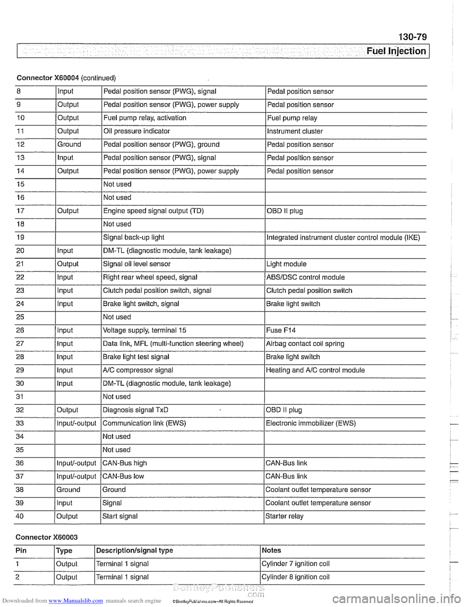
Connector X60004 (continued)
8 10
11
12
13
14
15
16
9
Output 0
Input
17
18
19
20
21
22
23
24
25
26
27
28
29
30
31
32
33
34
35
36
39
llnput lsignal l~oolant outlet temperature sensor
Output
Output
Ground
Input
Output
I I - I
40 /output Istart signal Istarter relay
Pedal position sensor (PWG), signal
Output Input
Output
input
Input
Input
Input
Input
Input
input
Input
Output
Input/-output
Input/-output
37
Connector X60003
Pedal position sensor
Fuel pump relay, activation
Oil pressure indicator Pedal position sensor (PWG), ground
Pedal position sensor (PWG), signal
Pedal position sensor (PWG), power supply
Not used
Not used Fuel
pump relay
Instrument cluster
Pedal position sensor
Pedal position sensor
Pedal position sensor
Engine speed signal output (TD)
Not used
Signal
back-up light
DM-TL (diagnostic module,
tank leakage)
Signal oil level sensor
Right rear wheel speed, signal
Clutch pedal position switch, signal
Brake light switch, signal
Not used
Voltage supply, terminal
15
Data link, MFL (multi-function steering wheel)
Brake light test signal
AJC compressor signal
DM-TL (diagnostic module, tank
leakage)
Not used
Diagnosis signal
TxD
Communication link (EWS)
Not used
Not used
CAN-BUS hiqh
38 1 Ground l~round I Coolant outlet temperature sensor
OED II plug
Integrated instrument cluster control module (IKE)
Light module
ABSIDSC control module
Clutch pedal position switch
Brake light switch
Fuse
F14
Airbag contact coil spring
Brake light switch
Heating and
A/C control module
OBD
II plug
Electronic immobilizer (EWS)
CAN-Bus link
CAN-Bus link
Input/-output CAN-Bus low
Page 551 of 1002

Downloaded from www.Manualslib.com manuals search engine
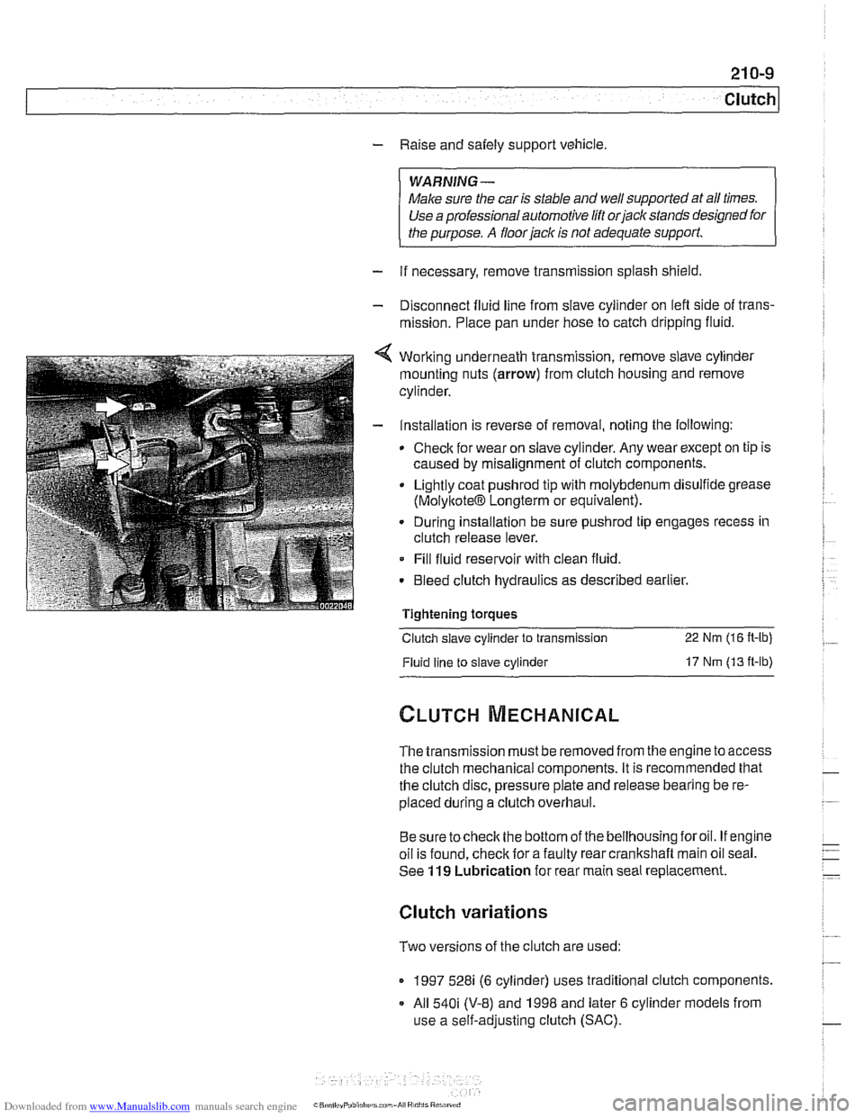
- Raise and safely support vehicle
WARNING-
Make sure the car is stable and well supporied at all times.
Use a professional automotive /iff orjack stands designed for
the
ournose. A floor jack is not adeouate suooort.
- If necessary, remove transmission splash shield.
- Disconnect fluid line from slave cylinder on lefl side of trans-
mission. Place pan under hose to catch dripping fluid.
4 Working underneath transmission, remove slave cylinder
mounting nuts (arrow) from clutch housing and remove
cylinder.
- Installation is reverse of removal, noting the following:
Check for wear on slave cylinder. Any wear except on tip is
caused by misalignment of clutch components.
Lightly coat
pushrod tip with molybdenum disulfide grease
(MolyltoteIB Longterm or equivalent).
. During installation be sure pushrod tip engages recess in
clutch release lever.
Fill fluid reservoir with clean fluid.
. Bleed clutch hydraulics as described earlier.
Tightening
toraues - -.
Clutch slave cylinder to transmission 22 Nm (16 R-lb)
Fluid line to slave cylinder 17 Nm (13 ft-lb)
The transmission must be removed from the engine to access
the clutch mechanical components. It is recommended that
the clutch disc, pressure plate and release bearing be re-
placed during a clutch overhaul.
Besure tocheck the bottom of the bellhousing foroil. If engine
oil is found, check for a faulty rear crankshaft main oil seal.
See
119 Lubrication for rear main seal replacement.
Clutch variations
Two versions of the clutch are used:
1997 528i (6 cylinder) uses traditional clutch components.
All
540i (V-8) and 1998 and later 6 cylinder models from
use a self-adjusting clutch (SAC).
Page 556 of 1002

Downloaded from www.Manualslib.com manuals search engine
210-1 4
1 Clutch
Dowel sleeve I
Check flywheel location
and correct installation. dowel sleeve
(arrow)
for . damage
< When installing dual-rnass flywheel, position dowel sleeve
next to two locating notches (arrows).
- Lightly oil flywheel mounting bolt threads and torque to
specification.
Tightening torque
Flywheel to crankshaft 105 Nm (77 ft-lb)
CAUTIOI\C
Do not reinstall flywheel bolls with LoctiteCTJ or similar thread
locl~ing compound.
- Install transm~ssion as descr~bed in 230 Manual Transmis-
sion.
4 If flywheel was replaced, check pulse sensor (arrow) for cor.
rect installation depth.
- Remove pulse sensor.
Page 559 of 1002

Downloaded from www.Manualslib.com manuals search engine
Clutch
- Remove flywheel locking tool
4 Inspect and clean release bearing lever. Apply a thin coat of
grease to release bearing lever lubrication points. Install re-
lease bearing. Bearing tabs
(A) align with contact points (B)
on release lever.
CAUTION-
Do not grease release bearing guide sleeve. If guide sleeve
is greased, release bearing may stick to it.
- Clean and lightly lubricate clutch disc splines and transmis-
sion input shaft splines.
- Install transmission. See 230 Manual Transmission
.
Transmission to engine
MB (Torx) 22 Nm (16 fl-lb)
MlO(Torx) 43 Nm (32 fl-lb)
Clutch, installing (new SAC components)
V-8 models and 1998 and later 6 cylinder models are
equipped with the self-adjusting clutch (SAC) pressure plate.
The SAC pressure plate, when new, comes from the factory
with a lock plate at the center which maintains spring tension
on the self-adjusting springs. This
loclting ring must not be re-
moved until the pressure plate is securely installed on tlie fly-
wheel with the clutch disk in place.
CAUTION-
Avoidcontaminating clutch friction surfaces with oilorgrease.
Do not touch these surfaces.
< Center clutch disc on flywheel using centering tool.
5-speed transmission: Special tool 21 2
142
- 6-speed transmission: Special tool 21 2 141
G6S-3782 transmission: Special tool 21 2 201
CAUTION-
Be sure clutch disc is facing the correct way The disc should
be marked "engine side" or "transmission side':
The large bolt in the clutch disc centering tool is used to
in-
stalland remove the tool only. Once the disc is in place on the
eel, remove the bolt to male room for tlie
SACpressure
Page 730 of 1002

Downloaded from www.Manualslib.com manuals search engine
(Rear Suspension
< Remove upper front control arm (traction strut) ball joint
mounting nut
(arrow). Press control arm ball joint out of
wheel bearing carrier.
- Repeat above process on upper rear control arm.
- Remove wheel bearing carrier assembly.
4 When reinstalling, pull axle shaft through wheel bearing car-
rier using
BMW special tools 33 2 115, 33 2 116 and 33 2
118.
- Lightly oil bearing surface of axle collar nut and install. T~ght-
en collar nut firmly, but do not fully tighten it at this time.
WARNING-
For safety reasons, the ale collar nut should only be tight-
ened to its final torque with the wheel installed and the car
lowered to
the ground. However, loading the bearing without
the nut tightened sufficiently may damage tlie bearing.
Page 734 of 1002

Downloaded from www.Manualslib.com manuals search engine
I Rear Suspension
4 Press out axle shaft using BMW special tools 33 2 117. 33 2
116and332111.
4 Remove upper front control arm (traction strut) ball joint
mounting nut (arrow). Press control arm ball joint out of
wheel bearing carrier.
- Repeat above process on upper rear control arm.
- Remove wheel bearing carrier assembly.
4 When reinstalling, pull axle shafl through wheel bearing car-
rier using BMW special tools 33
2 115, 33 2 116 and 33 2
118.
- Lightly oil bearing surface of axle collar nut and install. Tight-
en collar nut firmly, but do not fully tighten it at this time.
WARNING-
For safety reasons, the axle collar nut should only be tight-
ened to its final torque with the wheel installed and the car
lowered to the ground. However, loading the bearing without
the nut tiqhtened
suificiently may darnaqe the bearina.