2001 BMW 528i hood release
[x] Cancel search: hood releasePage 63 of 1002

Downloaded from www.Manualslib.com manuals search engine
Maintenance
BODY AND INTERIOR MAINTENANCE
Body and hinges, lubricating
Door locksand loclccylinderscan be lubricated with an oil that
contains graphite.
Body and doorhinges, hood latch and doorcheclc rods should
be lubricated with
SAE 30 or SAE 40 engine oil. Lubricate
seat runners with multipurposegrease. Do not apply any oil to
rubber parts.
If door weather-strips are sticking, lubricate
them with silicone spray or talcum powder. The hood release
cable should be lubricated as well.
The use of winter
lock deicer sprays should be lkept to an
absolute minimum, as the alcohol in the deicer will wash the
grease out of the lock assemblies and may cause locks to
corrode internally or to become difficult to operate.
Exterior washing
The longer dirt is left on the paint, the greater the risk of dam-
aging theglossy finish,
eitherby scratching or by thechemical
effect dirt particles may have on the painted surface.
Do not wash the car in direct sunlight. If the engine hood is
warm, allow it to cool. Beads of water not only leave spots
when dried rapidly by the sun or heat from theengine, but also
can act as small magnifying glasses and burn spots into the
finish. Wash the car with a mixture of lukewarm water and a
car wash product. Rinse using plenty of clear water. Wipe the
body dry with a sofl cloth towel or chamois to prevent
water-spotting.
Interior care
Dirt spots can usually be removed with lultewarm soapy water
or a dry foam cleaner. Use spot remover for grease and oil
spots. Do not pour the liquid directly on the carpet or fabric,
but dampen a clean cloth and rub carefully, starting at the
edge of the spot and working inward. Do not use gasoline,
naphtha, or other flammable substances.
Leather upholstery and trim
Leather upholstery and trim should be periodically cleaned
using a slightly damp cotton or wool cloth. The idea is to get
rid of the dirt in the creases and pores that can cause brittle-
ness and premature aging. On heavily soiled areas, use a
mild detergent (such as
wooliteQ) or other specially formulat-
ed leather cleaners. Dry the trim and upholstery completely
Page 76 of 1002

Downloaded from www.Manualslib.com manuals search engine
11 0-4
/Engine Removal and Installation
- Disconnect negative (-) cable from battery.
CAUTION- Prior to disconnecting the
batteg read the battery discon-
nection cautions
in 001 General Cautions and Warnings.
- Remove engine hood, or place in service position. See 410
Fenders, Engine Hood.
4 Remove left and right interior ventilation ducts (lefl side
shown):
Release ventilation filter cover latch (A) and remove cover.
Release plastic loclting tab
(6) or release locking tabs on
top of duct (later models).
Rotate duct counterclocltwise to
unloclt from bulkhead and
remove (arrow).
Disconnect electrical harness from hood switch (C).
Release spring
loclt (D).
Slide filter housing away from inner fender to remove.
Removal of right side ventilation duct is similar.
Remove rear bulkhead panel:
Remove rubber sealing gasket (arrow).
- Remove 3 mounting clips (A).
Remove
4 retaining screws (6).
Lift off panel.
Remove complete air filter housing:
Loosen
intalte duct hose clamp (A) at throttle assembly.
Loosen clamp and remove idle control line from intalte duct
(6) and (where applicable) disconnect idle speed control
valve electrical harness connector.
Disconnect harness connector (C) from mass air flow sen-
sor.
Remove air filter housing mounting screw (D).
Disconnect vent tube
(E).
Loosen air intake duct clamp (F).
Carefully lift air filter housing out of engine bay.
Page 88 of 1002

Downloaded from www.Manualslib.com manuals search engine
110-16
Engine Removal and Installation
ENGINE, REMOVAL AND
INSTALLATION (V-8 MODELS)
NOTE-
Engine removal procedures are similar for all V-8 models.
When differences exist, they are noted at the beginning of
each step. Engine are referred to by engine code. If neces-
sary, See
100 Engine-General for engine code andappli-
cation information.
Be sure to cover all painted surfaces before beginning the
removal procedure. As an aid to installation, label all com-
ponents, wires and hoses before removing them. Do not
reuse gaskets, O-rings or seals during reassembly
WARNING
-
Due to risk ofpersonal injury, be sure the engine is cold be-
fore beginning the
removal procedure.
- Disconnect negative (-) cable from battery.
Prior to disconnecting the battery, read the battery discon-
nection cautions given in
001 General Cautions and
Warnings.
- Remove engine hood or place hood in service position. See
410 Fenders, Engine Hood.
Remove
intake manifold cover, version 1:
Remove plastic trim caps (arrows).
Remove cover mounting fasteners and
lift off cover.
Remove intake manifold cover, version
2:
Press down on locking pins (arrows) to release locks
Lifl cover straight
up to remove.
Page 89 of 1002

Downloaded from www.Manualslib.com manuals search engine
- .. -.
-. Engine Removal and in=/
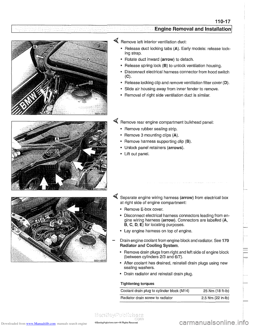
4 Remove left interior ventilation duct:
Release duct locking tabs (A). Early models: release
loclc
ing strap.
* Rotate duct inward (arrow) to detach.
Release spring
loclc (El) to unlock ventilation housing.
Disconnect electrical harness connector from hood switch
(C).
Release locking clip and remove ventilation filter cover (D).
Slide air housing away from inner fender to remove.
Removal
of right side ventilation duct is similar.
4 Remove rear engine compartment bulkhead panel:
Remove rubber sealing strip.
* Remove 3 mounting clips (A).
Remove harness supporting clip
(El).
Unlock panel retainers (arrows).
Lifl out panel.
< Separate engine wiring harness (arrow) from electrical box
at right side of engine compartment:
Remove E-box cover.
Disconnect electrical harness connectors leading from en-
gine wiring harness (arrow). Connectors are labelled (A,
El, C. D, E) for locating purposes.
Lay engine harness on top of engine.
- Drain engine coolant from engine block and radiator. See 170
Radiator and Cooling System.
Remove drain plugs from right and left side of engine
bloclc
(between cylinders 213 and 617).
Afler coolant has drained, reinstall drain plugs using new
sealing washers.
Drain radiator and reinstall drain plug.
Tightening
torques
Coolant drain plug to cylinder block (M14) 25 Nm (18 ft-ib)
Radiator drain screw to radiator 2.5
Nm (22 in-lb)
Page 103 of 1002

Downloaded from www.Manualslib.com manuals search engine
11 3-9
Cylinder Head Removal and Installation
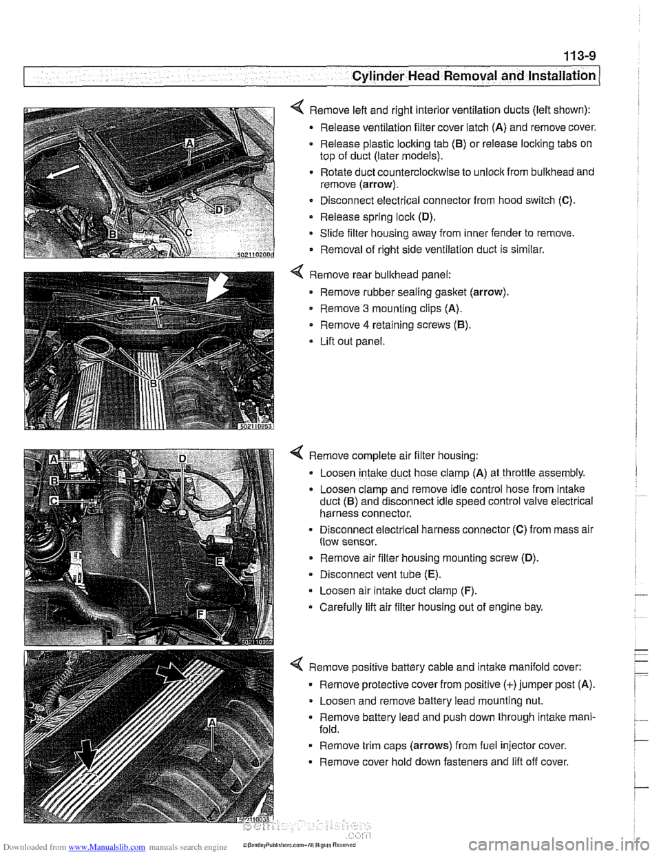
< Remove left and right interior ventilation ducts (left shown):
Release ventilation filter cover latch (A) and remove cover.
Release plastic locking tab
(6) or release locking tabs on
top of duct (later models).
Rotate duct counterclockwise to unlock from bulkhead and
remove (arrow).
Disconnect electrical connector from hood switch
(C).
Release spring lock (D).
Slide filter housing away from inner fender to remove.
Removal of right side ventilation duct is similar.
Remove rear bulkhead panel: Remove rubber sealing
gasket (arrow).
0 Remove 3 mounting clips (A).
Remove
4 retaining screws (6).
Lift out panel.
< Remove complete air filter housing:
Loosen
intake duct hose clamp (A) at throttle assembly.
Loosen clamp and remove idle control hose from
~ntake
duct (6) and disconnect Idle speed control valve electr~cal
harness connector.
Disconnect
electr~cal harness connector (C) from mass alr
flow sensor.
Remove air filter housing mounting screw (D).
Disconnect vent tube
(E).
Loosen air intake duct clamp (F).
Carefully lift air filter housing out of engine bay.
4 Remove positive battery cable and intake manifold cover:
Remove protective cover from positive (+)jumper post (A).
Loosen and remove battery lead mounting nut.
Remove battery lead and push down through intake mani-
fold.
Remove trim caps (arrows) from fuel injector cover.
Remove cover hold down fasteners and lift off cover.
Page 116 of 1002

Downloaded from www.Manualslib.com manuals search engine
1 13-22
Cylinder Head Removal and Installation
CYLINDER HEAD REMOVAL AND
~NSTALLATION (M52 TU AND N154
ENGINES)
WARNING -
Due to risk ofpersonal injur)c be sure the engine is cold be-
fore
beqinning the removal procedure.
Cylinder head removal and installation is a time consuming
repair procedure requiring multiple special service tools.
Read the entire procedure before beginning the repair.
This topic includes the following procedures:
* Cylinder head, removing, M52 TU and M54 engines
Cylinder head, installing,
M52 TU and M54 engines
Cylinder head, removing,
M52 TU and M54 engines
Allow engine to cool before beginning this procedure.
- Disconnect negative (-) cable from battery.
CAUTION-
Prior to disconnecting the battery, read the battery discon-
nection cautions in
001 General Cautions and Warnings.
4 Remove left and right interior ventilation ducts (left side
shown):
Release ventilation filter cover latch
(A) and remove cover.
Release plastic locking tab
(6) or release locking tabs on
top of duct (later models).
= Turn duct counterclocltwise to unlock from bullthead and
remove (arrow).
Disconnect electrical harness from hood switch (C).
Release spring lock fastener
(D).
- Slide filter housing away from inner fender to remove.
Removal of right side ventilation
dud
Remove rear bulkhead panel:
Lift off rubber sealing
gasket (arrow)
- Remove 3 mounting clips (A).
Remove 4 retaining screws (6).
Lift off panel.
: is similar
Page 151 of 1002

Downloaded from www.Manualslib.com manuals search engine
Cylinder Head Removal and Installation /
4 Remove top engine cover by releasing quick release fasten-
ers (arrows) by pressing down.
NOTE-
Earlier models may have an engine cover with pry off caps
and fasteners
In place of quick release fasteners.
4 Remove left and right interior ventilation ducts (left side
shown):
- Release locking tabs (A) or locking strap (early models, not
shown).
Release spring lock (B).
* Rotate duct inward (arrow) to remove.
Disconnect electrical harness from hood light switch (C).
Release locking clip and remove ventilation housing cover
(D).
Lift out housing from inner fender.
- Removal of right side ventilation housing is similar.
4 Air filter housing assembly, removing:
Disconnect electrical harness connectors from mass air
flow sensor (A) and temperature sensor (B).
Loosen hose clamp (C).
Remove filter housing mounting fastener (arrow) and re-
move filter housing with mass air flow sensor.
Page 215 of 1002

Downloaded from www.Manualslib.com manuals search engine
Cylinder Head and valvetrain1
Camshaft removal and installation
(M62 engine)
Camshafts, removing (M62 engine)
Special
BMW service tools should always be used to remove
and install the camshafts. Removal of the camshafts without
the special tools can result in personal injury and lor cylinder
head damage.
NOTE-
Cylinder bank 1-4 is referred to as the right cylinder bank
and is located on the passenger side. Cylinder bank 5-8 is
referred to as the left cylinder bank and is located on the driv-
er's side.
WARNING-
Allow enqine to cool before beqinninq this procedure. 1
- Disconnect negative (-) cable from battery.
CAUTION-
Prior to disconnecting the battery, read the battery discon-
nection cautions
in 001 General Cautions and Warnings.
- Dra~n coolant. See 170 Radiator and Cooling System.
Remove plastic engine covers:
Press down on locking pins (arrows) and remove top
cover.
Pry out
trlm caps (A) from covers.
Remove fasteners from beneath
trlm caps and remove
side covers.
4 Remove left and right interior ventilation filter housing (lefl
side shown):
Release locking tabs
(A) or locking strap (early models,
not shown).
Rotate duct inward (arrow) to disconnect.
- Release spring lock (6) to unloclc ventilation housing.
Disconnect electrical harness from hood switch
(C).
Release locking clip and remove ventilation filter cover (0).
Remove filter housing.
Removal of right side ventilation duct is similar.