2001 BMW 525i Switch hood
[x] Cancel search: Switch hoodPage 3 of 1002

Downloaded from www.Manualslib.com manuals search engine
YOU are now in Volume I
I
Foreword ................... .. ........................................................................\
.......... v
Index
........................ .. ................................................................ rear of manual
General, 001 General Warnings and Cautions 002 Vehicle Identification and VIN Decoder
Maintenance OiO 020 Maintenance
Engine
100 Engine-General 110 Engine Removal and Installation
113 Cylinder Head Removal and
Installation
116 Cyiinder Head and Valvetrain 117 Camshaft Timing Chain
119 Lubrication System
200 Transmission-General
2 Transmission 210 clutch 230 ManualTransmission
I20 Ignition System
121 Battery, Starter, Alternator
130 Fuel Injection
160 Fuel Tank and Fuel Pump 170 Radiator and Cooling System
180 Exhaust System
240 Automatic Transmission
250 Gearshift Linkage 260 Driveshaft
Suspension, 300 Suspension, Steering and 330 Rear Suspension
Brakes-General 331 Final Drive
Steering and No Front Suspension 340 Brakes
320 Steering and Wheel Alignment
400 Body-General
410 Fenders, Engine Hood 411 Doors
412 Trunk Lid, Tailgate
510 Exterior Trim, Bumpers 512 Door Windows
Equipment 513 Interior Trim
7
Equipment and 720 seat Belts
Accessories 721 Airbag System (SRS)
OBD On-Board Diagnostics
. ............ ..
515 Central Lociting and
Anti-Theft
520 Seats 540 Sunroof
.................................................................... Foreword .............................. .. v
Index ................... .. ................................................................ rear of manual
Electrical
6 system
600 Electrical System-General 620 Instruments
610 Electrical Comoonent Locations 630 Liohts
611 wipers and washers 612 Switches eati in^ and Air Conditioning
Radio
. ........... ........ .........................
Electrical Wiring Diagrams
Page 76 of 1002

Downloaded from www.Manualslib.com manuals search engine
11 0-4
/Engine Removal and Installation
- Disconnect negative (-) cable from battery.
CAUTION- Prior to disconnecting the
batteg read the battery discon-
nection cautions
in 001 General Cautions and Warnings.
- Remove engine hood, or place in service position. See 410
Fenders, Engine Hood.
4 Remove left and right interior ventilation ducts (lefl side
shown):
Release ventilation filter cover latch (A) and remove cover.
Release plastic loclting tab
(6) or release locking tabs on
top of duct (later models).
Rotate duct counterclocltwise to
unloclt from bulkhead and
remove (arrow).
Disconnect electrical harness from hood switch (C).
Release spring
loclt (D).
Slide filter housing away from inner fender to remove.
Removal of right side ventilation duct is similar.
Remove rear bulkhead panel:
Remove rubber sealing gasket (arrow).
- Remove 3 mounting clips (A).
Remove
4 retaining screws (6).
Lift off panel.
Remove complete air filter housing:
Loosen
intalte duct hose clamp (A) at throttle assembly.
Loosen clamp and remove idle control line from intalte duct
(6) and (where applicable) disconnect idle speed control
valve electrical harness connector.
Disconnect harness connector (C) from mass air flow sen-
sor.
Remove air filter housing mounting screw (D).
Disconnect vent tube
(E).
Loosen air intake duct clamp (F).
Carefully lift air filter housing out of engine bay.
Page 89 of 1002

Downloaded from www.Manualslib.com manuals search engine
- .. -.
-. Engine Removal and in=/
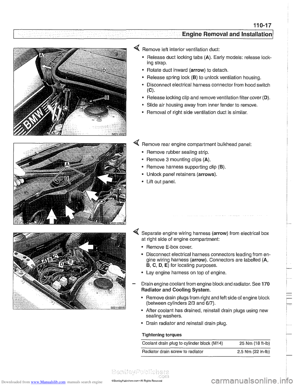
4 Remove left interior ventilation duct:
Release duct locking tabs (A). Early models: release
loclc
ing strap.
* Rotate duct inward (arrow) to detach.
Release spring
loclc (El) to unlock ventilation housing.
Disconnect electrical harness connector from hood switch
(C).
Release locking clip and remove ventilation filter cover (D).
Slide air housing away from inner fender to remove.
Removal
of right side ventilation duct is similar.
4 Remove rear engine compartment bulkhead panel:
Remove rubber sealing strip.
* Remove 3 mounting clips (A).
Remove harness supporting clip
(El).
Unlock panel retainers (arrows).
Lifl out panel.
< Separate engine wiring harness (arrow) from electrical box
at right side of engine compartment:
Remove E-box cover.
Disconnect electrical harness connectors leading from en-
gine wiring harness (arrow). Connectors are labelled (A,
El, C. D, E) for locating purposes.
Lay engine harness on top of engine.
- Drain engine coolant from engine block and radiator. See 170
Radiator and Cooling System.
Remove drain plugs from right and left side of engine
bloclc
(between cylinders 213 and 617).
Afler coolant has drained, reinstall drain plugs using new
sealing washers.
Drain radiator and reinstall drain plug.
Tightening
torques
Coolant drain plug to cylinder block (M14) 25 Nm (18 ft-ib)
Radiator drain screw to radiator 2.5
Nm (22 in-lb)
Page 103 of 1002

Downloaded from www.Manualslib.com manuals search engine
11 3-9
Cylinder Head Removal and Installation
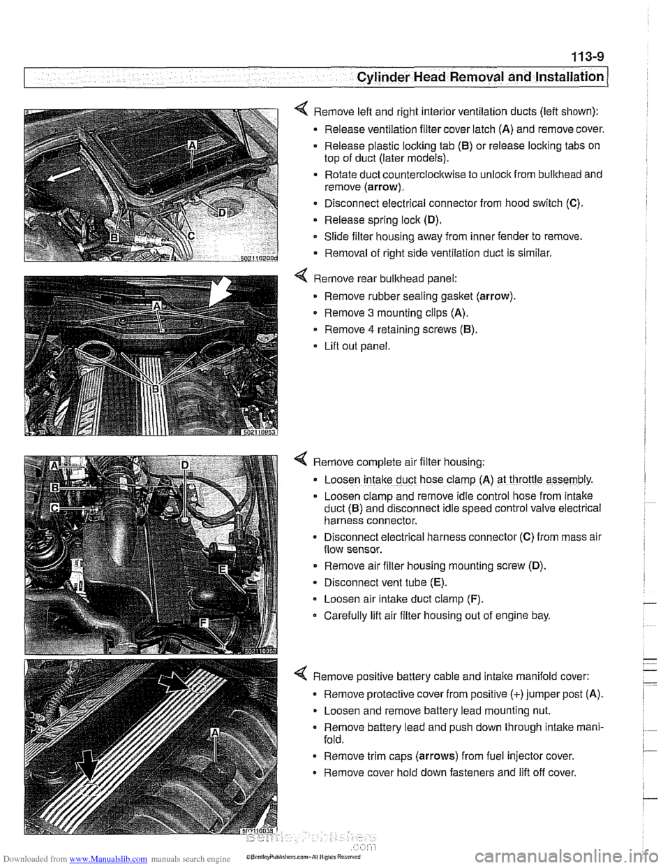
< Remove left and right interior ventilation ducts (left shown):
Release ventilation filter cover latch (A) and remove cover.
Release plastic locking tab
(6) or release locking tabs on
top of duct (later models).
Rotate duct counterclockwise to unlock from bulkhead and
remove (arrow).
Disconnect electrical connector from hood switch
(C).
Release spring lock (D).
Slide filter housing away from inner fender to remove.
Removal of right side ventilation duct is similar.
Remove rear bulkhead panel: Remove rubber sealing
gasket (arrow).
0 Remove 3 mounting clips (A).
Remove
4 retaining screws (6).
Lift out panel.
< Remove complete air filter housing:
Loosen
intake duct hose clamp (A) at throttle assembly.
Loosen clamp and remove idle control hose from
~ntake
duct (6) and disconnect Idle speed control valve electr~cal
harness connector.
Disconnect
electr~cal harness connector (C) from mass alr
flow sensor.
Remove air filter housing mounting screw (D).
Disconnect vent tube
(E).
Loosen air intake duct clamp (F).
Carefully lift air filter housing out of engine bay.
4 Remove positive battery cable and intake manifold cover:
Remove protective cover from positive (+)jumper post (A).
Loosen and remove battery lead mounting nut.
Remove battery lead and push down through intake mani-
fold.
Remove trim caps (arrows) from fuel injector cover.
Remove cover hold down fasteners and lift off cover.
Page 116 of 1002

Downloaded from www.Manualslib.com manuals search engine
1 13-22
Cylinder Head Removal and Installation
CYLINDER HEAD REMOVAL AND
~NSTALLATION (M52 TU AND N154
ENGINES)
WARNING -
Due to risk ofpersonal injur)c be sure the engine is cold be-
fore
beqinning the removal procedure.
Cylinder head removal and installation is a time consuming
repair procedure requiring multiple special service tools.
Read the entire procedure before beginning the repair.
This topic includes the following procedures:
* Cylinder head, removing, M52 TU and M54 engines
Cylinder head, installing,
M52 TU and M54 engines
Cylinder head, removing,
M52 TU and M54 engines
Allow engine to cool before beginning this procedure.
- Disconnect negative (-) cable from battery.
CAUTION-
Prior to disconnecting the battery, read the battery discon-
nection cautions in
001 General Cautions and Warnings.
4 Remove left and right interior ventilation ducts (left side
shown):
Release ventilation filter cover latch
(A) and remove cover.
Release plastic locking tab
(6) or release locking tabs on
top of duct (later models).
= Turn duct counterclocltwise to unlock from bullthead and
remove (arrow).
Disconnect electrical harness from hood switch (C).
Release spring lock fastener
(D).
- Slide filter housing away from inner fender to remove.
Removal of right side ventilation
dud
Remove rear bulkhead panel:
Lift off rubber sealing
gasket (arrow)
- Remove 3 mounting clips (A).
Remove 4 retaining screws (6).
Lift off panel.
: is similar
Page 151 of 1002

Downloaded from www.Manualslib.com manuals search engine
Cylinder Head Removal and Installation /
4 Remove top engine cover by releasing quick release fasten-
ers (arrows) by pressing down.
NOTE-
Earlier models may have an engine cover with pry off caps
and fasteners
In place of quick release fasteners.
4 Remove left and right interior ventilation ducts (left side
shown):
- Release locking tabs (A) or locking strap (early models, not
shown).
Release spring lock (B).
* Rotate duct inward (arrow) to remove.
Disconnect electrical harness from hood light switch (C).
Release locking clip and remove ventilation housing cover
(D).
Lift out housing from inner fender.
- Removal of right side ventilation housing is similar.
4 Air filter housing assembly, removing:
Disconnect electrical harness connectors from mass air
flow sensor (A) and temperature sensor (B).
Loosen hose clamp (C).
Remove filter housing mounting fastener (arrow) and re-
move filter housing with mass air flow sensor.
Page 215 of 1002

Downloaded from www.Manualslib.com manuals search engine
Cylinder Head and valvetrain1
Camshaft removal and installation
(M62 engine)
Camshafts, removing (M62 engine)
Special
BMW service tools should always be used to remove
and install the camshafts. Removal of the camshafts without
the special tools can result in personal injury and lor cylinder
head damage.
NOTE-
Cylinder bank 1-4 is referred to as the right cylinder bank
and is located on the passenger side. Cylinder bank 5-8 is
referred to as the left cylinder bank and is located on the driv-
er's side.
WARNING-
Allow enqine to cool before beqinninq this procedure. 1
- Disconnect negative (-) cable from battery.
CAUTION-
Prior to disconnecting the battery, read the battery discon-
nection cautions
in 001 General Cautions and Warnings.
- Dra~n coolant. See 170 Radiator and Cooling System.
Remove plastic engine covers:
Press down on locking pins (arrows) and remove top
cover.
Pry out
trlm caps (A) from covers.
Remove fasteners from beneath
trlm caps and remove
side covers.
4 Remove left and right interior ventilation filter housing (lefl
side shown):
Release locking tabs
(A) or locking strap (early models,
not shown).
Rotate duct inward (arrow) to disconnect.
- Release spring lock (6) to unloclc ventilation housing.
Disconnect electrical harness from hood switch
(C).
Release locking clip and remove ventilation filter cover (0).
Remove filter housing.
Removal of right side ventilation duct is similar.
Page 546 of 1002

Downloaded from www.Manualslib.com manuals search engine
Tool for bleeding clutch hydraulics (Tool No. 21 5 030)
21 5 030 I
The clutch is hydraulically actuated by the master and slave
cylinders. With the self-adjusting clutch
(SAC), clutch disc
wear is automatically taken up through the self-adjusting
pressure plate springs, making pedal feel consistent through-
out the life of the clutch.
A soft or spongy feel to the clutch pedal, long pedal free-play,
or grinding noises
from the gears while shifting can all indi-
cate problems with the clutch hydraulics. In these circum-
stances it is best to
star? with a clutch fluid flush, followed, if
necessary, by replacement of the hydraulic parts.
NOTE-
The clutch hydraulic system shares the fluid reservoir and flu-
id with the brake hydraulic system.
Clutch hydraulic system,
bleeding and flushing
If the clutchlbralte fluid is murky or muddy, or has not been
changed within the last two years, flush the system and
change the fluid. Flushing the old fluid from the clutch lines is
done using a bralte system pressure bleeder.
- Remove brake fluid reservoir cap. Using a clean syringe, re-
move brake fluid from reservoir. Refill reservoir with clean
DOT
4 bralte fluid.
Worlting inside engine compartment, remove left
interiorven-
tilation filter housing:
Release 3 plastic taps
(A) on duct. Earlier models use a
single release latch.
Rotate duct inward to remove.
Disconnect electrical harness to hood position switch.
Remove filter housing cover.
Release spring lock
(B) on interior ventilation housing and
remove housing.