2001 BMW 525i electronic
[x] Cancel search: electronicPage 467 of 1002

Downloaded from www.Manualslib.com manuals search engine
Fuel lnjection
I 1- I
4 /output l~em~erature signal. E-box fan I E-box fan
Connector
X60002 (continued)
14
15
16
17
18
19
20
21
22
23
24
5
6
7
8
9
10
11
12
13
14
15
16
Input
Input
Input
Input
Ground
Output Heated
oxygen sensor signal
Heated oxygen sensor signal
Heated oxygen sensor signal
Heated oxygen sensor signal
Not used
Heated oxygen sensor, heater ground
Not used
Not used
Not used
Terminal 85 control
Not used Heated oxygen sensor
II behind catalytic converter
Heated oxygen sensor
I in front of catalytic converter
Heated oxygen sensor
I1 in front of catalytic converter
Heated oxygen sensor
I behind catalytic converter
Heated oxygen sensor I in front of catalytic converter
Engine control module relay
Connector
X60003
Ground
Output Input
Ground
Output
Input
Input
Output
Output
Input
Pin 1
2
3
Not used
Ground for electronic components
Voltage supply for hot
film mass air flow sensor
Signal EDK (electric throttle actuator) Hot film mass air flow sensor, ground
Electric throttle actuator
Not used
Voltage signal, terminal 30h
Alternator
D+ (terminal 61) signal
Injection signal
Injection signal
VANOS valve, signal
Type
Output
Output
Output
Ground connector
X6460
Hot film mass air flow sensor
Electric throttle actuator
Hot film mass air flow sensor
Electric throttle actuator, voltage supply
Starter
Alternator (generator)
Cylinder
7 fuel injection valve
Cylinder 6 fuel injection valve
VANOS valve, cylinder
5-8
Descriptionlfunction
Injection signal
Injection signal
Signal evaporative emission valve Notes
Cylinder 2 fuel injector valve
Cylinder 3 fuel injector valve
Evaporative emission valve
Page 469 of 1002

Downloaded from www.Manualslib.com manuals search engine
Fuel Injection I
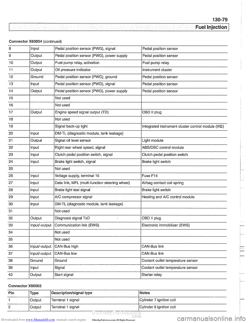
Connector X60004 (continued)
8 10
11
12
13
14
15
16
9
Output 0
Input
17
18
19
20
21
22
23
24
25
26
27
28
29
30
31
32
33
34
35
36
39
llnput lsignal l~oolant outlet temperature sensor
Output
Output
Ground
Input
Output
I I - I
40 /output Istart signal Istarter relay
Pedal position sensor (PWG), signal
Output Input
Output
input
Input
Input
Input
Input
Input
input
Input
Output
Input/-output
Input/-output
37
Connector X60003
Pedal position sensor
Fuel pump relay, activation
Oil pressure indicator Pedal position sensor (PWG), ground
Pedal position sensor (PWG), signal
Pedal position sensor (PWG), power supply
Not used
Not used Fuel
pump relay
Instrument cluster
Pedal position sensor
Pedal position sensor
Pedal position sensor
Engine speed signal output (TD)
Not used
Signal
back-up light
DM-TL (diagnostic module,
tank leakage)
Signal oil level sensor
Right rear wheel speed, signal
Clutch pedal position switch, signal
Brake light switch, signal
Not used
Voltage supply, terminal
15
Data link, MFL (multi-function steering wheel)
Brake light test signal
AJC compressor signal
DM-TL (diagnostic module, tank
leakage)
Not used
Diagnosis signal
TxD
Communication link (EWS)
Not used
Not used
CAN-BUS hiqh
38 1 Ground l~round I Coolant outlet temperature sensor
OED II plug
Integrated instrument cluster control module (IKE)
Light module
ABSIDSC control module
Clutch pedal position switch
Brake light switch
Fuse
F14
Airbag contact coil spring
Brake light switch
Heating and
A/C control module
OBD
II plug
Electronic immobilizer (EWS)
CAN-Bus link
CAN-Bus link
Input/-output CAN-Bus low
Page 500 of 1002

Downloaded from www.Manualslib.com manuals search engine
-
I Radiator and Cooling System
Mechanical thermostat
(M52 engine)
4 The mechanical thermostat relies on coolant temperature to
operate. While coolant is cold, it remains closed, and circu-
lating coolant bypasses the radiator for rapid engine warm
up. At higher coolant temperature, the thermostat progres-
sively opens to allow coolant flow through the radiator, thus
controlling engine temperature. Port
A restricts coolant flow
from radiator, and port
B restricts coolant flow to radiator.
Electrically heated thermostat
4 The electrically heated thermostat is DME map-controlled.
The engine control module (ECM) activates the thermostat to
maintain engine coolant temperature within a narrow range.
In case of failure of the electronics, the mechanical function of
the thermostat acts as a fail-safe.
Radiator and expansion tank
The radiator is a crossflow design. An expansion tank pro-
vides for coolant expansion at higher temperatures and easy
monitoring of the coolant level.
On cars with automatic transmission, ATF is circulated
through an additional heat exchanger (ATF cooler).
Mechanical cooling fan with viscous clutch
The mechanical cooling fan is belt-driven via a viscous fluid
coupling (clutch) attached to the front of the coolant pump.
The fan clutch controls the speed of the fan based on the tem-
perature of the air flowing through the radiator core.
Electric (auxiliary) cooling fan
The electric cooling fan is mounted on the bumper side of the
radiator.
In models manufactured up to
911 998 (M52 or 1997 M62 en-
gine), the electric cooling fan is controlled by a dual tempera-
ture fan switch mounted in the side of the radiator.
Page 504 of 1002

Downloaded from www.Manualslib.com manuals search engine
170-8
I Radiator and Cooling System
Common cooling system faults can be grouped into one of 4
categories:
Cooling system
lealts
Poor coolant circulation
Radiator cooling fan faults
Electrical/electronic faults
Cooling system inspection
- Check that coolant pump drive belt tensioner is functioning
properly and that belt tension is correct. Belt tensioner sys-
tems for the different models are shown in
020 Maintenance.
- Check condition of coolant pump drive belt.
- Checlc coolant hoses for cracks or softness. Checlc clamps
for looseness. Check coolant level and check for evidence of
coolant
lealts from engine.
- Check that radiator fins are not blocked with dirt or debris.
Clean radiator using low-pressure water or compressed air.
Blow outward, from engine side out.
- To check coolant pump:
Remove mechanical cooling fan. See Mechanical
(vis.
cous clutch) cooling fan, removing and installing.
Remove drive belt from coolant pump pulley. See
020
Maintenance.
Firmly grasp opposite sides of pulley and check for play in
all directions.
Spin pulley and check that shaft runs smoothly without
play.
NOTE-
The coolant provides lubrication for the pump shaft, so an oc-
casional drop of coolant
lealing from the pump is acceptable.
If coolant drips steadily from the vent hole, replace the pump.
- At normal engine operating temperature, cooling system is
pressurized. This raises boiling point of coolant.
Leaks may
prevent system from becoming pressurized. If visual evi-
dence is inconclusive, pressure test cooling system as de-
scribed later to help pinpoint hard-to-find leaks.
- If cooling system is full of coolant and holds pressure:
- Use an appropriate scan tool to interrogate engine control
module (ECM) for radiator fan or DME control circuit faults.
Checlc for loose or worn drive belt.
0 Test for failed thermostat or coolant pump impeller. Some
pumps may be fitted with plastic impellers.
Page 589 of 1002

Downloaded from www.Manualslib.com manuals search engine
- .- -
Automatic Transmission
Electronics are used to control the operation of these auto-
matic transmissions. Steptronic transmission functions are
also programmed into the transmission control module
(TCM). The TCM monitors transmission operation for faults
and alerts the driver by illuminating the transmission fault indi-
cator on the instrument panel. Diagnostic trouble codes
(DTCs) stored in the TCM may be downloaded and interpret-
ed by trained technicians using special BMW diagnostic
equipment.
Some minor automatic transmission problems can be cor-
rected by changing the automatic transmission fluid (ATF)
and filter. Begin by checking ATF level and condition.
Checlc
to see if the fluid is dirty or has a burned odor indicating over-
heated fluid. The burned odor may be the results of burned
discs in theclutch paclts. The friction material from the burned
disc can clog valve body passages.
NOTE-
The E39 automatic transmission is not equipped with a dip-
stick.
Checking the ATF level must be done while monitoring
the ATF temperature with the engine idling. The
BMW dealer
is equipped with the special equipment to make this check.
Page 600 of 1002

Downloaded from www.Manualslib.com manuals search engine
250-2
I Gearshift Linkage
This repair group covers transmission gearshift and linkage service for both manual and automatic transmission
equipped vehicles.
To gain access to the complete gearshift mechanism it is
necessary to remove the exhaust system and the driveshaft
as described in
180 Exhaust System and 260 Driveshaft.
NOTE-
In models with automatic transmission, the electronic immo-
bilizer
(EWS) prevents starter operation unless the gear po-
sition is Park or Neutral.
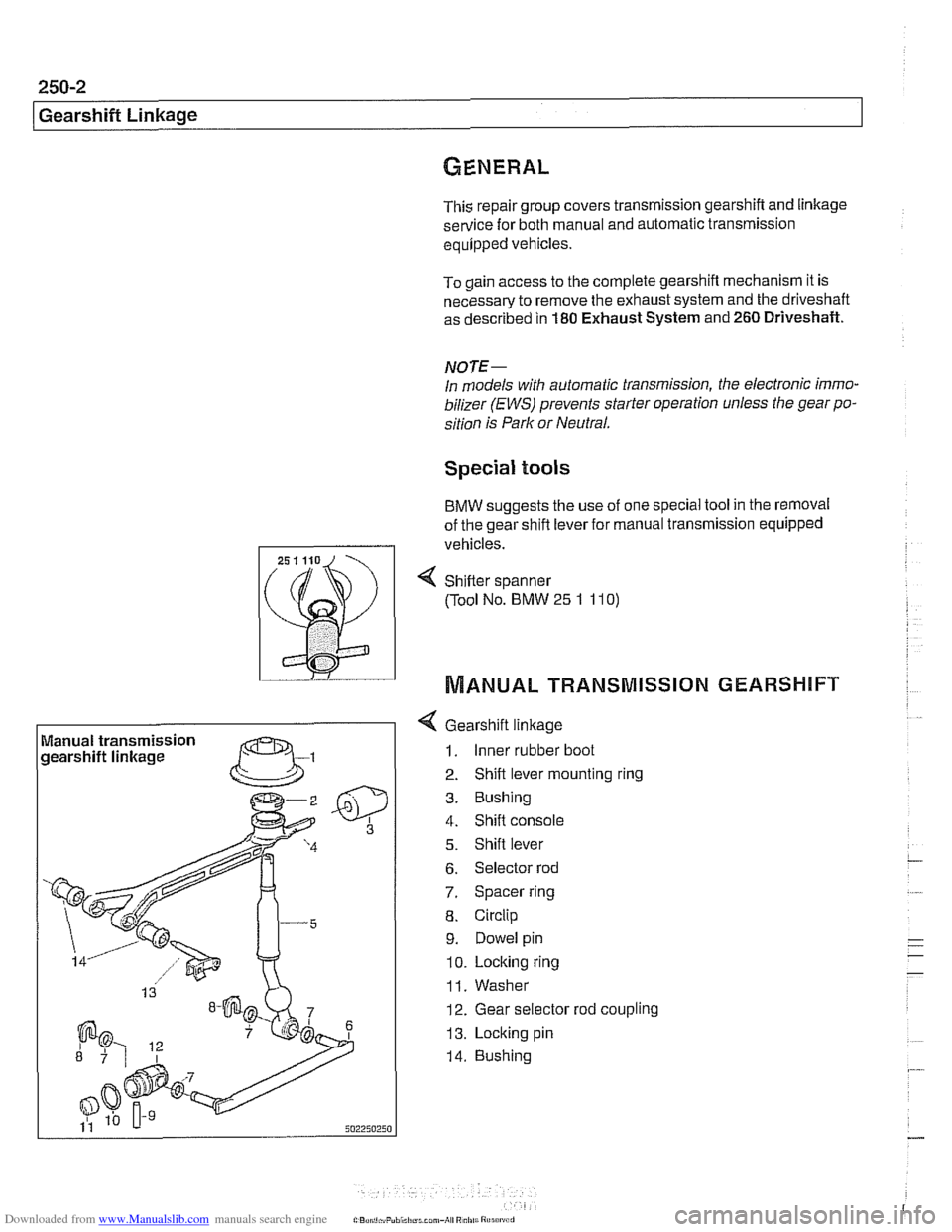
Special tools
BMW suggests the use of one special tool in the removal
of the gear shift lever for manual transmission equipped
I I vehicles.
Manual transmission
gearshift linkage
--
4 Gearshift linkage
1. Inner rubber boot
2. Shift lever mounting ring
3. Bushing
4. Shift console
5. Shift lever
6. Selector rod
7. Spacer ring
8. Circlip
9. Dowel pin
10. Locking ring
11. Washer
12. Gear selector rod coupling
13. Locking pin
14. Bushing
4 Sh~fter spanner
(Tool No. BMW
25 1 11 0)
MANUAL TRANSMISSION GEARSHIFT
Page 621 of 1002

Downloaded from www.Manualslib.com manuals search engine
300 Suspension. Steering and Brakes .
Genera8
General ........................... .30 0.2
Aluminum suspension components
...... .30 0.2
Front Suspension ................. .30 0.2
Front suspension 6-cylinder models
(525i.5281. 530i) ..................... .30 0.3
Front suspension V-8 models (540i) ...... .30 0.4
Rear Suspension .................. .30 0.5
Sedan models
....................... .30 0.5
Rear suspension sedan models ........ .30 0.6
Sport Wagon models ................. .30 0.6
Rear suspension Sport Wagon
(with coil springs)
.................... .30 0.7
Rear suspension Sport Wagon
(EHC with air springs)
................. .30 0.8
EHC operational diagram .............. .30 0.9
Steering ......................... .30 0.10
Rack-and-pinion steering ............. .30 0.10
Recirculating ball and nut steering ...... .30 0.10
..................... Brake System 300-10
Wheels and Tires ................. 300-1 1
............... Rim and tire sizes table 300-1 1
Electronic Brake and Stability
.................. Control Systems 300-1 1
E39 electronic brake and stability
........ control systems application table 300-12
........................ ABS system 300-1 2
Automatic Stability Control (ASC)
....... 300-12
ABSIASC traction control system ....... 300-13
Dynamic Stability Control (DSC)
........ 300-14
Ride Height ....................... 300-14
......... Front ride height specifications 300-1 5
......... Rear ride height specifications 300-16
Page 622 of 1002

Downloaded from www.Manualslib.com manuals search engine
[~us~ension, Steering and Brakes - General
This section of the manual covers front and rear suspension,
braking and steering systems, and contains wheel, tire and
wheel alignment information and specifications. Also covered
here are the integrated braking and suspension systems in-
cluding
antilock braking (ABS), traction control (ASCIDSC),
and electronic height control (EHC).
Vehicle ride height information is at the end of this repair
group. Alignment information is in
320 Steering and Wheel
Alignment.
Aluminum suspension components
In order to reduce vehicle weight, aluminum suspension com-
ponents are used in some models. A test with a magnet will
easily reveal the metal used. If working with aluminum com-
ponents, be sure to read and follow the cautions below.
CAUTION-
* Due to the chemical and corrosion characteristics of alumi-
num, do not bring into contact with battery acid.
Do not use wire brushes with brass or iron bristles.
Only use brushes with stainless steel bristles.
Do not expose to flying sparks from
grinding/cutting op-
erations.
Do not subject to steel welding splashes.
Do not expose to temperatures over
80°C (176"F),
even for short periods. Temperatures in painting facili-
ties are not a problem.
The E39 front suspension subframe is used as a rigid mount-
ing platform for the front suspension arms, stabilizer bar and
steering gear.
The suspension arms, known as the lower control arms and
the tension struts (thrust arms), are connected to the
sub-
frame through rubber bushings. The arms are connected to
the steering
knucltles in a double pivot configuration.
Each front strut assembly includes a tubular strut and a coil
spring. The upper strut mount includes a bearing. The lower
end of each strut housing is fitted to the steering knuckle. The
integral wheel bearing and hub are bolted to the steering
Iknucltle.
6-cylinder and V-8 models use different steering systems and
other front suspension components.