Page 461 of 1002

Downloaded from www.Manualslib.com manuals search engine
Fuel Injection I
Engine coolant temperature (ECT) sensor,
testing
The ECT sensor is located on the front of the engine in the
coolant~thermostat flange. The ECT sensor is a dual temper-
ature sensor. One circuit provides coolant temperature infor-
mation to the ECM while the other circuit provides coolant
temperature information to the instrument cluster.
The ECM determines the correct ignition timing and
airlfuel
mixture required for the engine by monitoring an applied volt-
age
(5 vdc) to the sensor. Thevoltage drop across the sensor
varies as the coolant temperature (sensor resistance) chang-
es.
NOTE-
The ECT sensor is an NTC (negative temperature coeffi-
cient) type sensor. In other words, as the temperature rises,
resistance through the sensor decreases.
If the ETC sensor input is faulty or non-plausible, the MIL is il-
luminated when OBD
II fault criteria are exceeded. The ECM
assumes a substitute value
(80" C/ 176°F) to maintain engine
operation. The ignition timing is set to a
conse~ativelsafe ba-
sic setting.
Disconnect harness from
ECTsensor (A) at coolant flange at
front of engine.
- Check ECT sensor resistance using a multimeter at sensor
terminals
3 and 4. Peel back protective boot (B) to ID termi-
nal numbers on connector housing.
I ECT sensor resistance @ 20" C (68°F) I 2.2 - 2.7 lkCi
Engine coolant temperature (ECT) sensor,
replacing
I WARNING-
/ Due to risk ofpersonal injury, be sure the engine is cold be- I
I fore replacin~~~~sensor. -
-
I
- Disconnect ECT sensor harness.
- Unscrew ECT sensor from cylinder head and install new sen-
sor.
Use new copper sealing washers when installing sensor.
Replace any lost coolant.
Tightening torque
ECT sensor to coolant flange 13 Nm (10 it-lb)
Page 581 of 1002

Downloaded from www.Manualslib.com manuals search engine
--.
- - Manual Transmission
- V-8 engine: Remove heat shield from left front axle support.
< V-8 engine: Remove engine speed reference sensor from
transmission.
- Where applicable, remove brackets for transmission under-
body protection (adjacent to transmission).
4 Support transmission with transmission jack.
- Where applicable, remove reinforcing cross brace from
below driveshaft at transmission.
- Disconnect harness connector from back-up light switch
on transmission.
- Free harnesses for oxygen sensors and back-up lights
from crossmember and transmission.
Remove transmission crossmember: Remove transmission mount bolts
(A).
Remove transmission crossmember bolts (B)
Where applicable, remove bolts (C).
NOTE-
5-speed transmission shown in illustration. Crossmember
assembly for 6-speed transmission is similar.
Disconnect driveshaft from transmission and hang to one
side. See
260 Driveshaft.
I CAUTION- I
Do not damage constant velocity joint orprotective boot at
rear differential.
- 6-cylinder engine: Remove stabilizer bar links and swivel sta-
bilizer bar
u~wards.
Page 600 of 1002

Downloaded from www.Manualslib.com manuals search engine
250-2
I Gearshift Linkage
This repair group covers transmission gearshift and linkage service for both manual and automatic transmission
equipped vehicles.
To gain access to the complete gearshift mechanism it is
necessary to remove the exhaust system and the driveshaft
as described in
180 Exhaust System and 260 Driveshaft.
NOTE-
In models with automatic transmission, the electronic immo-
bilizer
(EWS) prevents starter operation unless the gear po-
sition is Park or Neutral.
Special tools
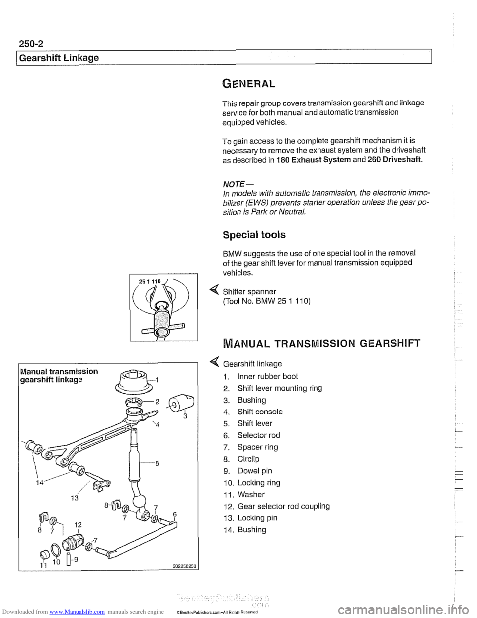
BMW suggests the use of one special tool in the removal
of the gear shift lever for manual transmission equipped
I I vehicles.
Manual transmission
gearshift linkage
--
4 Gearshift linkage
1. Inner rubber boot
2. Shift lever mounting ring
3. Bushing
4. Shift console
5. Shift lever
6. Selector rod
7. Spacer ring
8. Circlip
9. Dowel pin
10. Locking ring
11. Washer
12. Gear selector rod coupling
13. Locking pin
14. Bushing
4 Sh~fter spanner
(Tool No. BMW
25 1 11 0)
MANUAL TRANSMISSION GEARSHIFT
Page 601 of 1002

Downloaded from www.Manualslib.com manuals search engine
Gearshift ~inkaael
Gearshift lever, removing
(manual transmission)
Use the accompanying illustration as a guide when removing
and installing the gearshift linkage.
- Remove shift knob by pulling knob straight off shift lever.
NOTE-
Pull up on the shift knob with about 90 lbs. of force. Do not
twist
knob or locating key can be damaged.
- Squeeze sides of shift boot to unclip from center console.
Pull boot up and off shift lever.
- Remove sound insulation at base of shift lever.
- Raise vehicle to gain access to underside of vehicle.
- --
WARNING-
Male sure the car is stable and well supported at all tfmes.
Use a professional automotwe hft orjaclc stands designed for
the purpose.
A floorjaclc 1s not adequate support.
- Remove complete exhaust system. See 180 Exhaust
System.
- Remove driveshaft. See 260 Driveshaft.
- Support transmission with transmission jack. Remove
crossmember from rear of transmission.
- Lower rear of transmission to access gearshift linkage.
CA UTIOI\C
Tilting the engine to lower the transmission can lead to
damage to various components due to lack of clearance.
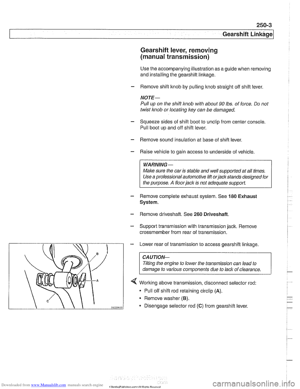
4 Working above transmission, disconnect selector rod:
* Pull off shift rod retaining circlip (A).
Remove washer (6).
Disengage selector rod (C) from gearshift lever.
Page 602 of 1002

Downloaded from www.Manualslib.com manuals search engine
250-4
I Gearshift Linkage
Release gearshift lever mounting ring from below using BMW
special spanner 25 1 110. Turn tool 90' ('I, turn)
counterclockwise.
Push shift lever up to remove from shift console,
Raise transmission and temporarily install transmission
crossmember.
Lower vehicle. Working from inside passenger compart-
ment, pull up on shift lever to remove it together with inner
rubber boot and shift lever mounting ring.
Gearshift lever, installing
(manual transmission)
- Clean old grease from shift lever ball and mounting ring.
Also clean shift console bowl. Lubricate with molybdenum
disulfide grease.
- Insert shift lever together with inner boot and mounting ring
into center console.
4 Align shift lever mounting ring locking tabs with slots
(arrows) in shift console bowl. Press down until ring
snaps into place.
NOTE-
lnstall mounting ring witli arrow pointing toward front of car.
4 Pull inner rubber boot over shift console bowl (arrows) to
seal base of shift lever.
NOTE-
lnstall rubber boot witli arrow pointing toward front of car.
- Raise car and support transmission. Remove transmission
crossmember and lower transmission to access base of shift
lever.
CAUTIOI\C
Tilting the engine to lower the transmission can lead to
damage to various components due to lack of clearance.
Page 603 of 1002
Downloaded from www.Manualslib.com manuals search engine
Gearshift Linkage
- Connect selector rod to shift lever. Lift transmission, install
crossmember and tighten crossmember bolts.
Install driveshaft and heat shield. See
260 Driveshaft.
Reinstall exhaust system. See 180 Exhaust System.
. Lower vehicle. Install shift boot. Push shift ltnob on lever.
Tightening torque
Driveshaft
CV joint to final drive flange
. MI0 (Tom bolt)
70 Nm (51 ft-lb)
. M8 (compression nut) 32 Nm (24 ft-lb) - Driveshaft clamping sleeve
- MI0 ribbed nuts
80 Nm (59 ft-lb)
MI0 compressed nuts 64 Nm (47 ft-lb)
Flex-disc to driveshaft or transmission flange
MlO (8.8 grade) 48
Nm (35 ft-lb)
. MI0 (10.9 grade) 60
Nm (44 ft-lb)
- MI2 (10.9 grade) 100 Nm (74 ft-ib)
MI4 140 Nm (103 fi-lb)
Transmission crossmember
. to transmission 21 Nm (15 ft-lb)
. to chassis 42 Nm (30 ft-lb)
Page 615 of 1002
Downloaded from www.Manualslib.com manuals search engine
4 Remove nuts (arrows) from constant velocity joint mounting
bolts at final drive. Pry constant velocity joint free from final
drive input flange at groove
(A).
- Hang driveshaft rear section from body using stiff wire.
< Do not let driveshaft hang unsupported, as rear CV joint rub-
ber boot (arrow) may be damaged.
4 Remove center support bearing mounting nuts (arrows)
- Remove driveshaft. Pull down on center of driveshaft to
facilitate removal.
CAUTIOI\C
Protect CVjoint with plastic cover.
Page 620 of 1002

Downloaded from www.Manualslib.com manuals search engine
260-14
Driveshaft
Constant velocity (CV) joint, replacing
The CV joint at the rear of the driveshaft is available from
BMW as a separate part.
- Remove complete driveshaft as described earlier in this
section.
< Clean grease off CV joint. Remove retaining circlip (arrow)
from CV joint end of driveshaft.
- Drive out bolts from CV joint.
4 Remove CV joint from driveshaft:
Pry back protective boot
(A).
- Using BMW special tool 26 1 110 on inner race (B), press
or pull joint off shaft.
- Check protective boot for damage. Replace if necessary.
- lnstall new CV joint:
. Working from both sides of joint, inject approximately 80
grams of
OptimolB grease (or equivalent) into joint.
Install new sealing gasket on joint face that mates with pro-
tective boot. Seal fits in groove on outer race of joint.
Clean grease off driveshaft and mating splines on joint.
Apply
LoctiteO 648 to driveshaft splines.
Press new CV joint onto shaft as far as it will go.
CAUTIOI\C
Only press on inner CVjoint race.
- Install new retaining circlip to end of driveshaft,
- Insert CV joint mounting bolts. Be sure to reuse washers.
- Install driveshaft as described earlier in this section.