2001 BMW 525i electrical system general
[x] Cancel search: electrical system generalPage 71 of 1002

Downloaded from www.Manualslib.com manuals search engine
Two common causes of driveability problems are incorrect
system voltage and bad grounds.
System voltage
Digital motor electronics (DME) requires that the system (bat-
tery) voltage be maintained within a narrow range of DC volt-
age.
DC voltage levels beyond or below the operating range,
or any
AIC voltage in the electrical system can cause havoc.
When troubleshooting an illuminated MIL, make sure the bat-
tery is fully charged and capable of delivering all its power to
the electrical system. An undercharged battery can amplify
AIC alternator output ripple.
To
make a quick check of the battery charge, measure the
voltage across the battery terminals with all cables attached
and the ignition off.
Afully charged battery will measure 12.6
volts or slightly more, compared to 12.1 5 volts for a battery
with a 25% charge.
The DME system operates at low voltage and current levels,
making it sensitive to small increases in resistance. The elec-
trical system is routinely subjected to corrosion, vibration and
wear, so faults or corrosion in the wiring harness and connec-
tors are not uncommon. Check the battery terminals
forcorro-
sion or loose cable connections. See 121 Battery, Starter,
Alternator for additional information.
If a battery cable connection has no
v~sible faults but is still
suspect, measure the voltage drop across the connection. A
large drop indicates excessive resistance, meaning that the
connection is corroded, dirty, or damaged. Clean or repairthe
connection and retest.
NOTE-
For instructions on conducting a voltage drop test and other
general electrical troubleshooting information, see
600 Elec-
trical System-General.
Visually inspect all wiring, connectors, switches and fuses in
the system. Loose or damaged connectors can cause inter-
mittent problems, especially the small terminals in the ECM
connectors. Disconnect the wiring harness connectors to
check for corrosion, and use electrical cleaning spray to re-
move contaminants.
Main grounds
Good grounds are critical to proper DME operation. If a
ground connection has no visible faults but is still suspect.
measure the voltage drop across the connection. A large volt-
age drop means high resistance. Clean or repair the connec-
tion and retest.
LBuntr.yP~sbhnllcn.can#-AII A,~iltl Rcsrwsd
Page 72 of 1002

Downloaded from www.Manualslib.com manuals search engine
100-6
( Engine-General
The main grounds for the fuel and ignition circuits of the DME
system are illustrated below; see 610 Electrical Component
Locations for additional ground and component locations.
4 Ground for engine management system in right rear of en-
gine compartment on E-box bulkhead (arrow).
6-cylinder models: Grounds
for ignition coils (arrows)
4 V-8 models: Grounds for ignition coils, at cylinders 3
(arrow) and 7.
4 Fuel pump ground (arrow) below right tail light in luggage
compartment.
NOTE-
Ground location for sedan shown, wagon models may
differ.
Page 215 of 1002

Downloaded from www.Manualslib.com manuals search engine
Cylinder Head and valvetrain1
Camshaft removal and installation
(M62 engine)
Camshafts, removing (M62 engine)
Special
BMW service tools should always be used to remove
and install the camshafts. Removal of the camshafts without
the special tools can result in personal injury and lor cylinder
head damage.
NOTE-
Cylinder bank 1-4 is referred to as the right cylinder bank
and is located on the passenger side. Cylinder bank 5-8 is
referred to as the left cylinder bank and is located on the driv-
er's side.
WARNING-
Allow enqine to cool before beqinninq this procedure. 1
- Disconnect negative (-) cable from battery.
CAUTION-
Prior to disconnecting the battery, read the battery discon-
nection cautions
in 001 General Cautions and Warnings.
- Dra~n coolant. See 170 Radiator and Cooling System.
Remove plastic engine covers:
Press down on locking pins (arrows) and remove top
cover.
Pry out
trlm caps (A) from covers.
Remove fasteners from beneath
trlm caps and remove
side covers.
4 Remove left and right interior ventilation filter housing (lefl
side shown):
Release locking tabs
(A) or locking strap (early models,
not shown).
Rotate duct inward (arrow) to disconnect.
- Release spring lock (6) to unloclc ventilation housing.
Disconnect electrical harness from hood switch
(C).
Release locking clip and remove ventilation filter cover (0).
Remove filter housing.
Removal of right side ventilation duct is similar.
Page 258 of 1002

Downloaded from www.Manualslib.com manuals search engine
Camshaft Timing Chain
VANOS timing, checking and adjusting
(M52 engine)
NOTE-
* Special BMW service tools are required to remove and in-
stall the VANOS control unit. Read the procedure through
before starting the job.
If the camshafts are not properly timed, the pistons can
contact the valves.
- Disconnect negative (-) cable from battery.
CAUTIOG Disconnecting the battery may erase
faultcode(s) storedin
control module memory. Prior to disconnecting the battery,
checlc for fault codes using special BMW diagnostic equip-
ment.
Prior to disconnecting the battery, read the battery dis-
connection cautions given in
001 General Cautions
and Warnings.
- Remove viscous clutch cooling fan. See 170 Radiator and
Cooling
System.
CAUTIOG The radiator cooling fan nut
(32 mm wrench) has left-hand
threads.
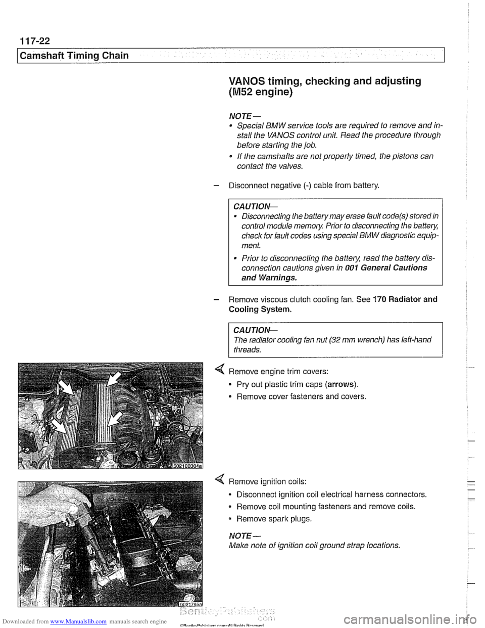
4 Remove ignition coils:
Disconnect ignition coil electrical harness connectors.
Remove coil mounting fasteners and remove coils.
Remove
spark plugs.
NOTE-
Make note of ignition coil ground strap locations.
Page 273 of 1002

Downloaded from www.Manualslib.com manuals search engine
Camshaft Timing Chain
VANOS control unit, removing
(M52 TU and M54 engines)
This procedure includes removal of the Double VANOS con-
trol unit.
NOTE-
If the Double VANOS control unit is being replaced, camshaft
timing must be checked. This procedure requires multiple
special tools. Be sure to read the procedures through before
beginning the repair.
- Working inside luggage compartment, disconnect negative
(-) battery cable.
Prior to disconnecting the
batteg read the battery discon-
nection cautions given in
001 General Cautions and
Remove engine cooling fan assembly. See 170 Radiator
and Cooling System.
Remove engine trim covers.
Pry out plastic trim caps (arrows).
Remove cover fasteners, oil filler cap, and covers.
Remove ignition coils:
Disconnect ignition coil electrical harness connectors.
Remove coil mounting fasteners and coils.
NOTE-
Make note of ignition coil ground strap locations.
Remove spark plugs,
Page 367 of 1002

Downloaded from www.Manualslib.com manuals search engine
121-1
121 Battery. Starter. Alternator
General ........................... .I2 1.2
Special tools ........................ .I2 1.2
Engine electrical system ............... .I2 1.2
Battery Safety Terminal ............... .I2 1.3
Warnings and cautions ................. 121 -4
Battery ............................ 121-5
Battery testing ...................... .I2 1.5
Hydrometer testing ................... .I2 1.5
Battery open-circuit voltage test ......... .I2 1.6
Battery load voltage test ................ 121 -6
Closed-circuit current measurement ..... .I2 1.7
Battery charging ...................... 121 -9
Battery safety terminal, replacing ......... 121-9
Alternator (generator) ............. .I2 1.10
Alternator. basic .................... .I2 1.11
Alternator with multi-function
control (MFR)
...................... .I2 1.11
Water-cooled alternator ............... 121 -12
Charging System Troubleshooting . 121-12
Charging system quick-check .......... 121-13
Charging system. checking ............ 121-13
Alternator. removing and installing
(6-cylinder engine)
.................. 121 -1 5
Alternator. removing and installing
(M62 engine. air cooled)
.............. 121-16
Alternator. removing and installing
(M62 TU engine. water cooled) ......... 121-1 8
Starter ........................... 121 -1 9
Starter troubleshooting ............... 121 -1 9
Starter. removing and installing
(6-cylinder engine)
.................. 121-20
Starter. removing and installing
(V-8 engine)
........................ 121 -21
Solenoid switch. removing and installing . . 121-23
Page 368 of 1002

Downloaded from www.Manualslib.com manuals search engine
- -
Battery, Starter, Alternator
This section covers the battery, alternator, starter and associ-
ated components of the electrical system.
Troubleshooting information
forthese components isfound in
Table a. Battery, alternator and starter troubleshooting.
For additional electrical troubleshooting information, see
600 Electrical System-General.
Special tools
4 Automotive digital multimeter
CAUTION-
Only use a digital multirneter when testing automotive electri- I) cal components.
4 Closed-circuit current measurement adaptor
(Tool No.
BMW 61 2 300)
Engine electrical system
The alternator and starter are wired directly to the battery. To
prevent accidental shorts that might blow a fuse or damage
wires and electrical components, always disconnect the
negative
(-) battery cable before working on the electrical
system.
Various versions of alternators, voltage regulators, starters,
and batteries are used in
E39 cars. Replace components ac-
cording to the original equipment specification.
Page 381 of 1002

Downloaded from www.Manualslib.com manuals search engine
Battery, Starter, ~lternatorl
Alternator, removing and installing
(6-cylinder engine)
A replacement alternator should have the same rating as the
original. Alternator manufacturer and ampere rating are nor-
mally marked on the alternator housing.
- Disconnect negative (-) battery cable.
CAUTION-
Prior to disconnecting the batteg read the battery discon-
nection cautions given
in 001 General Warnings and Cau-
I tions.
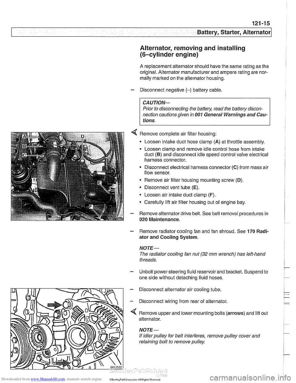
Remove complete air filter housing:
Loosen intake duct hose clamp
(A) at throttle assembly.
Loosen clamp and remove idle control hose from intake
duct
(B) and disconnect idle speed control valve electrical
harness connector.
Disconnect electrical harness connector
(C) from mass air
flow sensor.
* Remove air filter housing mounting screw (D),
Disconnect vent tube (E).
Loosen air intake duct clamp (F).
Carefully lifl air filter housing out of engine bay.
Remove alternator drive belt. See belt removal procedures in
020 Maintenance.
- Remove radiator cooling fan and fan shroud. See 170 Radi-
ator and Cooling System.
NOTE-
The radiator cooling fan nut (32 mm wrench) has left-hand
threads.
- Unbolt power steering fluid reservoir and bracket. Suspend to
one side without detaching fluid hoses.
- Disconnect alternator air cooling tube.
- Disconnect wiring from rear of alternator.
'4 Remove upper and lower mounting bolts (arrows) and lift
alternator.
If idler pulley for belt interferes, remove pulley cover and
retaining bolt to remove pulley. out