2001 BMW 525i Heating
[x] Cancel search: HeatingPage 455 of 1002

Downloaded from www.Manualslib.com manuals search engine
Fuel Injection
Table Pin
24
25
26
27
28
29
30
31
32
33
34
35
36
37
38
39
40
1
2
3
4
5
6
7
8
9
e. Bosch 5.2.1
Signal
Input
Input
Ground
Output Input- output
Output
Input- output
Input- output
Output
Connector
X60005
Output
Output
Output
Output
Ground
Output
Output
Output
Output
ECM pin assignments
Description
Not used
Not used
Voltage supply, terminal
15
Not used
Not used
Compressor ON signal from engine control module
(DME)
Ground
Not used
Diagnosis signal TXD
Communication
link (EWS)
Signal, leak diagnosis pump
Not used
CAN-Bus high
CAN-Bus low Not used
Not used
Start
signal
Terminal 1 signal
Terminal
1 signal
Terminal
1 signal
Terminal
1 signal
Ground
Terminal
1 signal
Terminal
1 signal
Terminal
1 signal
Terminal 1 signal Note
Fuse
F14
Heating
and AIC control module
Lealtage diagnosis pump
Data
iinit connector
Electronic immobilizer (EWS)
Leakage diagnosis pump (LDP)
CAN link
CAN link
Starter relay
Cylinder
7 ignition coil
Cylinder 8 ignition coil
Cylinder
2 ignition coil
Cylinder
3 ignition coil
Ground point
Cylinder
1 ignition coil
Cylinder
4 ignition coil
Cylinder 5 ignition coil
Cylinder
6 ignition coil
Page 469 of 1002

Downloaded from www.Manualslib.com manuals search engine
Fuel Injection I
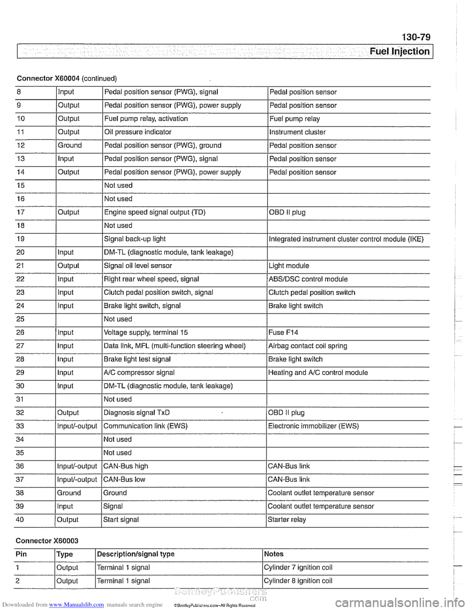
Connector X60004 (continued)
8 10
11
12
13
14
15
16
9
Output 0
Input
17
18
19
20
21
22
23
24
25
26
27
28
29
30
31
32
33
34
35
36
39
llnput lsignal l~oolant outlet temperature sensor
Output
Output
Ground
Input
Output
I I - I
40 /output Istart signal Istarter relay
Pedal position sensor (PWG), signal
Output Input
Output
input
Input
Input
Input
Input
Input
input
Input
Output
Input/-output
Input/-output
37
Connector X60003
Pedal position sensor
Fuel pump relay, activation
Oil pressure indicator Pedal position sensor (PWG), ground
Pedal position sensor (PWG), signal
Pedal position sensor (PWG), power supply
Not used
Not used Fuel
pump relay
Instrument cluster
Pedal position sensor
Pedal position sensor
Pedal position sensor
Engine speed signal output (TD)
Not used
Signal
back-up light
DM-TL (diagnostic module,
tank leakage)
Signal oil level sensor
Right rear wheel speed, signal
Clutch pedal position switch, signal
Brake light switch, signal
Not used
Voltage supply, terminal
15
Data link, MFL (multi-function steering wheel)
Brake light test signal
AJC compressor signal
DM-TL (diagnostic module, tank
leakage)
Not used
Diagnosis signal
TxD
Communication link (EWS)
Not used
Not used
CAN-BUS hiqh
38 1 Ground l~round I Coolant outlet temperature sensor
OED II plug
Integrated instrument cluster control module (IKE)
Light module
ABSIDSC control module
Clutch pedal position switch
Brake light switch
Fuse
F14
Airbag contact coil spring
Brake light switch
Heating and
A/C control module
OBD
II plug
Electronic immobilizer (EWS)
CAN-Bus link
CAN-Bus link
Input/-output CAN-Bus low
Page 479 of 1002

Downloaded from www.Manualslib.com manuals search engine
.- -
Fuel Tank and Fuel purnpl
Fuel pump power consumption, testing
To achieve accurate test results, the battery voltage at the
fuel pump connector should be
12.6 volts. Charge the battery
as necessary.
A higher than normal power consumption may indicate a
worn fuel pump, which may cause intermittent fuel starvation
due to pump overheating and seizure. The only remedy is
pump replacement.
A lower than normal power consumption
may indicate a blockage. Be sure to check that the return line
and the pump pickup are not obstructed before replacing the
pump.
- Expose right side access cover:
Peel forward lip of carpet.
Release rubber grommet from center of access cover insu-
lation.
Peel back insulation at perforations to expose fuel tank ac-
cess cover.
Remove right side cover to expose electrical harness con-
nector.
Disconnect harness connector from tank sending unit by slid-
ing lock back. Lift off connector.
Test fuel pump for current draw by attaching digital ammeter
between pump and harness (terminal
2, whitelblue wire) and
connect a jumper wire between pump and harness (terminal
1, brown wire) as shown.
CAUTION-
Do not allow the test leads to short to ground.
NOTE-
See 600 Electrical Systern-General for information on elec-
trical tests
using a digital multirneter.
Run pump as described in Operating fuel pump for tests.
- Compare ammeter reading with specification listed in ac-
companying table.
Fuel
pump current
Current consumption (average) 9.5 amps
Page 498 of 1002

Downloaded from www.Manualslib.com manuals search engine
I Radiator and Cooling System
This section covers component repair information for the en-
gine cooling system.
Heater core replacement is covered in
640 Heating and Air
Conditioning.
Special tools
Special tools are necessaryfor belt-driven fan clutch removal
and also for pressure testing the cooling system.
4 Cooling fan counterhold wrench
(Tool No. BMW
11 5 030)
4 Cooling fan wrench
(Tool No. BMW
11 5 040)
< Expansion tank cap test adaptor
(Tool No.
BMW 17 0 007)
17 0 002 4 Cooling system pressure tester set
1 17 o 005 (Tool No. BMW 17 0 OOZi17 0 005)
Page 503 of 1002

Downloaded from www.Manualslib.com manuals search engine
Warnings and cautions
Obse~e the following warnings and cautions when worlting
on the cooling system.
WARNING -
. At normal operating temperature the cooling system is
pressurized. Allow the system to cool as long as possible
before opening (a minimum of one hour), then release the
cap slowly to allow safe release ofpressure.
a Releasing the coolant system pressure lowers the cool-
ant boilingpoint and the coolant may boil suddenly. Use
1 heavy and wear eye and face protection to
guard against scalding.
Use extreme care when draining and disposing of en-
gine coolant. Coolant is poisonous and lethal to hu-
mans andpets. Pets are attracted to coolant because
of its sweet smell and taste. Seek medical attention im-
mediately if coolant is ingested.
CAUTIOG
Avoid adding cold water to the coolant while the engine is
hot or overheated. If it is necessary to add coolant to a
hol
system, do so only with the engine running and coolanl
pump turning.
To avoid excess silicate gel precipitation in the cooling
system and loss of cooling capacity, use BMW coolant
or equivalent low silicate antifreeze.
a If oil enters the cooling system, the radiator, expansion
tank and heating circuit must be flushed with cleaning
agent. BMW recommends removal of the radiator and
expansion
tank to flush.
When
worlcing on the cooling system, cover the alter-
nator to protect it against coolant drips.
Prior to disconnecting the battery, read the battery dis-
connection cautions given in
001 General Warnings
and Cautions.
Begin the diagnosis of cooling system problems with a thor-
ough visual inspection.
If no visual faults are found, it is rec-
ommend that the engine control module (ECM) fault memory
be checked for stored diagnostic trouble codes
(DTCs) using
BMW scan tool
DlSplus or equivalent.
Page 510 of 1002

Downloaded from www.Manualslib.com manuals search engine
Radiator and Cooling System
Cooling system, bleeding
Trapped air in the cooling system can prevent proper coolant
circulation and overheating. Wheneverthe coolant is drained
and filled, bleed the cooling system to remove trapped air.
4 Loosen bleed screw (arrow) on radiator expansion tank.
- Set temperature controls in passenger compartment to full
warm, set blower to low setting and turn ignition to
ON posi-
tion (do not start engine).
CAUTIOIG
On late model cars with latent heat pump, do not turn ignition
to ON position.
- Slowly add coolanUdistilled water mixture to expansion tank
until it spills from bleed screw. When coolant spilling from
bleed screws is free of air bubbles, tighten screw and replace
cap on expansion tank.
Run engine until it reaches operating temperature,
- After engine has cooled, recheck coolant level.
Top up so that coolant level indicator is at MAX.
- If trapped air cannot be bled manually, pressure-bleed sys-
tem using cooling system pressure tester.
CA UTlON--
Always use genuine BMW coolant or its equivalent to avoid
the formation of harmful, clogging deposits
in the cooling sys-
tem.
Tightening torque
Radiator bleed screw to radiator 2.5 Nm (22 in-lb)
Mechanical (viscous clutch) cooling fan,
removing and installing
The procedure given here describes the removal of the me-
chanical fan and fan shroud. It is possible to remove the fan
without the shroud.
< Working at top of fan shroud:
Remove expansion tank bleed screw (arrow) and expan-
sion tank locking tabs.
Push top of expansion
tank toward engine and lift to free
from lower mounts.
- Remove two expansion rivets in upper corners of fan shroud.
Unclip expansion tank bleed hose located under shroud.
Page 709 of 1002

Downloaded from www.Manualslib.com manuals search engine
330-1 3
Rear Suspension
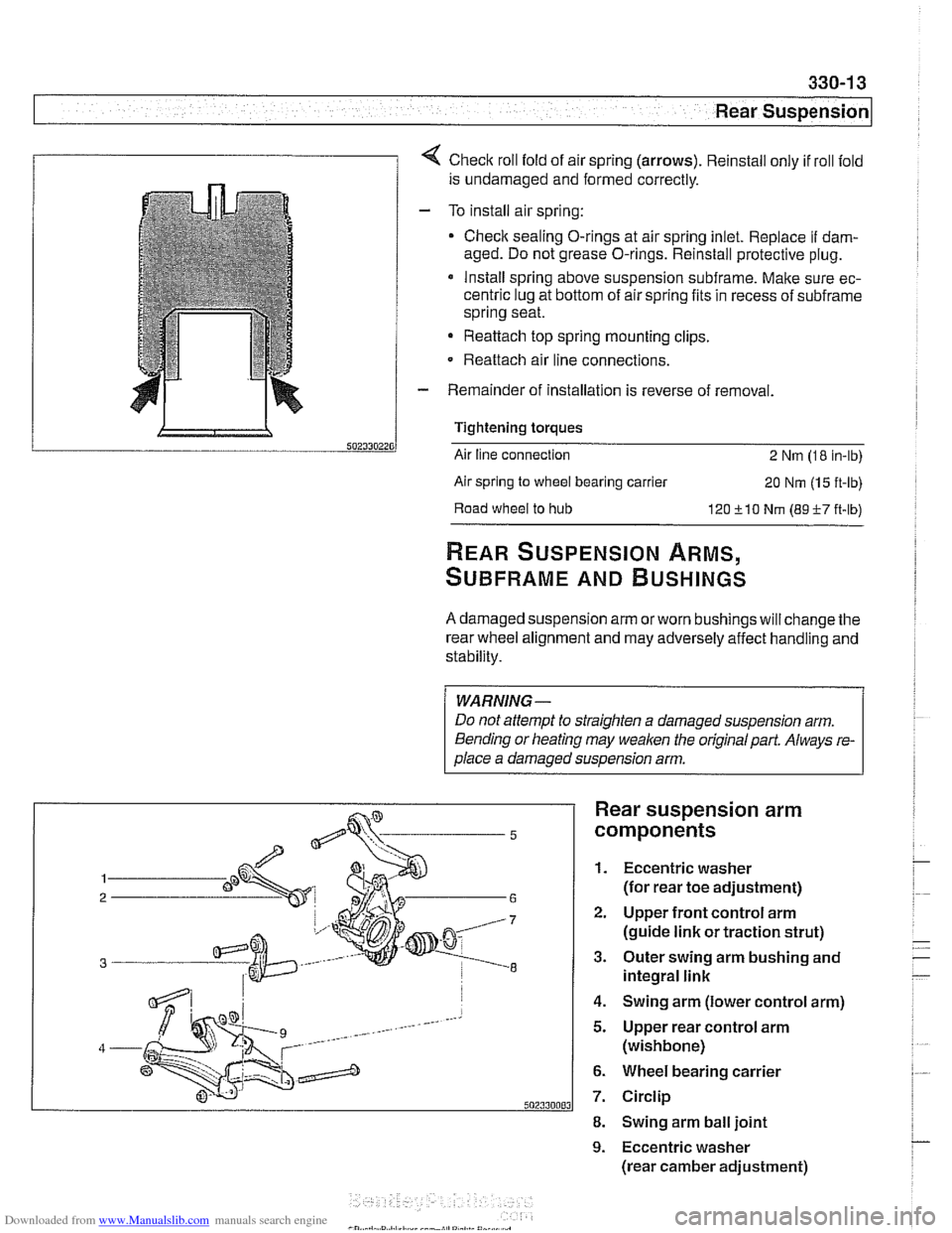
1 1 4 Check roll fold of air spring (arrows). Reinstall only if roll fold
is undamaged and formed correctly.
- To install air spring:
Check sealing O-rings at air spring inlet. Replace
if dam-
aged. Do not grease O-rings. Reinstall protective plug.
* Install spring above suspension subframe. Make sure ec-
centric lug at bottom of air spring fits in recess of
subframe
spring seat.
Reattach top spring mounting clips.
- Reattach air line connections.
- Remainder of installation is reverse of removal.
Tightening torques
Air line connection
2 Nm (1 8 in-lb)
Air spring
to wheel bearing carrier 20 Nm (1 5 ft-lb)
Road
wheel to hub 120 510 Nm (89-F-7 ft-lb)
REAR SUSPENSION ARMS,
SUBFRAME AND BUSHINGS
A damaged suspension arm orworn bushings will change the
rear wheel alignment and may adversely affect handling and
stability.
WARNING-
Do not attempt to straighten a damaged suspension arm.
Bending or heating may
weaken the original part. Always re-
olace a damaoed susoension arm.
Rear suspension arm
components
1. Eccentric washer
(for rear toe adjustment)
2. Upper front control arm
(guide link or traction strut)
3. Outer swing arm bushing and
integral link
4. Swing arm (lower control arm)
5. Upper rear control arm
(wishbone)
6. Wheel bearing carrier
7. Circlip
8. Swing arm ball joint
9. Eccentric washer
(rear camber adjustment)
Page 727 of 1002

Downloaded from www.Manualslib.com manuals search engine
Rear Suspension
- Remainder of installation is reverse of removal, noting the fol-
lowing.
Tighten suspension arm and shock absorber fasteners to
final torque only afler vehicle has been lowered and sus-
pension has settled.
Tightening torques
ABS pulse sensor to wheel bearing carrier 8
Nrn (6 ft-lb)
Air line connection 2 Nrn (18 in-lb)
Brake rotor to hub 16
Nrn (12 ft-lb)
Driveshaft
CV joint to final drive flange
- MI0 (Torx bolts) 70
Nrn (51 ft-lb)
- MB (compression nut) 32 Nrn (24 ft-lb)
Rear
brake pad carrier (caliper) to wheel 65
Nrn (48 ft-lb)
bearing carrier
Road wheel to hub
120ilO Nrn
(89 i-7 ft-lb)
Rear subframe mounting bushings,
removing and installing
- Remove rear subframe mounting bolts as described earlier.
Lower
subframe approximately 40 - 45 mm (1 -2 in).
4 Install BMW special tools 33 4 140,33 4 151,33 4 154,33 4
155,33 4 156 as shown.
Use hot air gun with a maximum output temperature of
600°C (1100" F) to heat bushing area of subframe for no
more than
2 minutes. Remove rubber mount from sub-
frame.
CAUTION-
Aluminum suspension parts may be severely damaged
witli intense heat
* Heating for 2 minutes with the recommended heat
source is intended to
keep the temperature of the alu-
minum
parts below the safety threshold of 80°C
(1 76°F). .