Page 83 of 1002

Downloaded from www.Manualslib.com manuals search engine
Engine Removal and installatid
4 Remove cylinder head top cover:
Remove plastic trim caps
(arrows).
Remove cover retaining fasteners and lifl off cover.
- Remove alternator cooling tube.
4 Drain engine coolant and remove coolant hoses:
* Remove expansion tank cap on coolant reservoir.
Place a
3 gallon pail beneath engine to capture coolant,
* Remove coolant drain plug located on exhaust side of
cylinder
2 of engine block (arrow).
NOTE-
Drain plug for M52 TU and M54 engine shown. Plug for M52
located between cylinders 4 and 5.
Drain radiator by removing plastic drain plug (arrow) from
bottom of radiator.
WARNING-
Use extreme caution when draining and disposing of engine
coolant Coolant is poisonous andlethal to humans andpets.
Pets are attracted to coolant because of its sweet smell and
taste. Seek medical attention immediately if coolant is ingest-
ed.
NOTE-
Catch and dispose of drained coolant according to local,
state, and federal laws.
Page 92 of 1002

Downloaded from www.Manualslib.com manuals search engine
11 0-20
Engine Removal and Installation
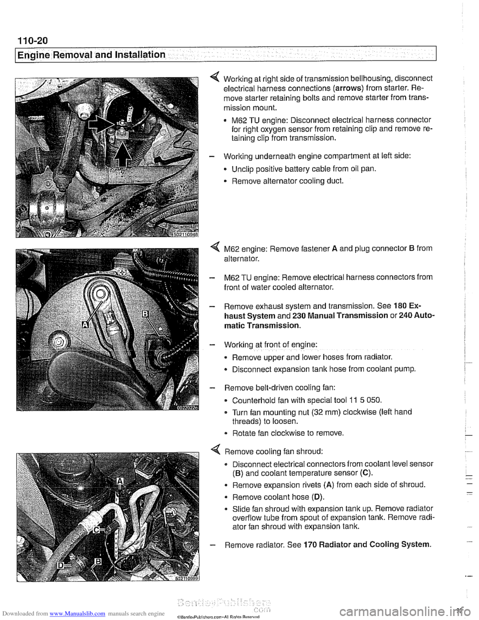
Working at right side of transmission bellhousing, disconnect
electrical harness connections (arrows) from starter. Re-
move starter retaining bolts and remove starter from trans-
mission mount.
M62 TU engine: Disconnect electrical harness connector
for right oxygen sensor from retaining clip and remove re-
taining clip from transmission.
- Working underneath engine compartment at left side:
Unclip positive battery cable from oil pan.
. Remove alternator cooling duct.
4 M62 engine: Remove fastener A and plug connector B from
alternator.
- M62 TU engine: Remove electrical harness connectors from
front of water cooled alternator.
- Remove exhaust system and transmission. See 180 Ex-
haust System and 230 Manual Transmission or 240 Auto-
matic Transmission.
- Working at front of engine:
Remove upper and lower hoses from radiator.
D~sconnect expansion tank hose from coolant pump.
- Remove belt-driven cooling fan:
Counterhold fan with special tool
11 5 050.
Turn fan mounting nut (32 mm) clockwise (left hand
threads) to loosen.
Rotate fan clockwise to remove.
Remove cooling fan shroud:
Disconnect electrical connectors from coolant level sensor
(B) and coolant temperature sensor (C).
. Remove expansion rivets (A) from each side of shroud
Remove coolant hose
(D).
Slide fan shroud with expansion tank up. Remove radiator
overflow tube from spout of expansion tank. Remove radi-
ator fan shroud with expansion tank.
Remove radiator. See
170 Radiator and Cooling System.
Page 94 of 1002
Downloaded from www.Manualslib.com manuals search engine
Engine Removal and Installation
Tightening torques
ATF cooler lines to radiator
(use new O-rings)
MI8 cap nut 20 Nm (15 ft-lb)
M22 cap nut
22
Nm (17 ft-lb
Coolant drain plug to cylinder
blocic (M14) 25 Nm (18 ft-lb)
Engine mount to engine bracket or 47 Nm (35 ft-lb)
subframe (M10)
Exhaust flange nuts (8 mm) 25 Nm (18 ff-ib)
Radiator cooling fan to coolant pump 40 Nm (30 ft-lb)
(left-hand threads)
Radiator drain screw to radiator 2.5 Nm (22 in-lb)
Wirino to alternator
(ME nut) 13 Nm (9.5 ft-lb)
Page 262 of 1002

Downloaded from www.Manualslib.com manuals search engine
Camshaft Timing Chain Timing chains, removing
(M52 engine)
Camshaft timing chain removal on M52 engines requires en-
gine oil pan removal.
Special
BMW sewice tools are needed for timing chain re-
moval and installation procedures. The special tools assure
propertiming of thevalvetrain. Precise marks to
setthe timing
on the camshafts are not provided for reassembly. Read the
procedures through before beginning the job.
NOTE-
If the camshafts are not properly timed, the pistons can con-
tact the valves.
- Remove VANOS control unit. See VANOS control unit, re-
moving (M52 engine).
- Remove radiator cooling fan and shroud. See 170 Radiator
and Cooling System.
- Drain cooling system. See 170 Radiator and Cooling Sys-
tem.
- Remove coolant hoses from thermostat housing and remove
thermostat housing from front of cylinder head.
- Loosen bolts for coolant pump pulley.
- Remove drive belts for alternator and AIC compressor. See
020 Maintenance.
- Remove coolant pump pulley.
Remove drive belt tensioner mounting bolts (arrows) and re-
move tensioner from front of engine.
- Remove engine speed sensor from lower timing chain cover.
Page 305 of 1002
Downloaded from www.Manualslib.com manuals search engine
-
Camshaft Timing chain1
4 Remove oil lines from camshaft supports (arrows).
- Remove radiator cooling fan and fan shroud. See 170 Radi-
ator and Cooling System.
NOTE-
The radiator cooling fan nut (32 mm wrench) has left-hand
threads.
- Remove engine drive belts alternator and AlC compressor.
See
020 Maintenance.
4 Remove vibration damper bolts (arrows) and remove
damper.
4 Mount BMW special tool 11 2 450 to crankshaft hub while
aligning damper locator pin with hole (arrow) in special tool.
CAUTION-
Crankshaft center bolt is torqued to 410 Nm (300 ft-lb) use
BMWspecial tool I I 2 450 to secure crankshaft when remov-
ing center bolt.
- Loosen and remove cranltshaff center bolt.
Page 306 of 1002
Downloaded from www.Manualslib.com manuals search engine
I Camshaft Timins Chain
4 Using special tool 11 2 450, rotate engine clocltwise to TDC
with number one cylinder cam lobes facing each other (ar-
rows)
as shown.
4 Lock crankshaft in TDC position with BMW special tool 11 3
200 (arrow).
- Remove BMW special tool 11 2 450 and remove hub.
- Remove upper engine oil pan. See 119 Lubrication.
- Remove alternator. See 121 Battery, Starter, Alternator.
- Remove retaining bolt for oil dipstick tube from upper timing
chain cover on right side.
- Remove camshaft position sensor from right upper timing
chain cover.
< Remove right upper timing chain cover:
Remove chain tensioner
(A).
CAUTIOG
Tensioner is under spring tension. Release slowly. 1
Release fasteners (arrows) and remove cover
Page 367 of 1002

Downloaded from www.Manualslib.com manuals search engine
121-1
121 Battery. Starter. Alternator
General ........................... .I2 1.2
Special tools ........................ .I2 1.2
Engine electrical system ............... .I2 1.2
Battery Safety Terminal ............... .I2 1.3
Warnings and cautions ................. 121 -4
Battery ............................ 121-5
Battery testing ...................... .I2 1.5
Hydrometer testing ................... .I2 1.5
Battery open-circuit voltage test ......... .I2 1.6
Battery load voltage test ................ 121 -6
Closed-circuit current measurement ..... .I2 1.7
Battery charging ...................... 121 -9
Battery safety terminal, replacing ......... 121-9
Alternator (generator) ............. .I2 1.10
Alternator. basic .................... .I2 1.11
Alternator with multi-function
control (MFR)
...................... .I2 1.11
Water-cooled alternator ............... 121 -12
Charging System Troubleshooting . 121-12
Charging system quick-check .......... 121-13
Charging system. checking ............ 121-13
Alternator. removing and installing
(6-cylinder engine)
.................. 121 -1 5
Alternator. removing and installing
(M62 engine. air cooled)
.............. 121-16
Alternator. removing and installing
(M62 TU engine. water cooled) ......... 121-1 8
Starter ........................... 121 -1 9
Starter troubleshooting ............... 121 -1 9
Starter. removing and installing
(6-cylinder engine)
.................. 121-20
Starter. removing and installing
(V-8 engine)
........................ 121 -21
Solenoid switch. removing and installing . . 121-23
Page 368 of 1002

Downloaded from www.Manualslib.com manuals search engine
- -
Battery, Starter, Alternator
This section covers the battery, alternator, starter and associ-
ated components of the electrical system.
Troubleshooting information
forthese components isfound in
Table a. Battery, alternator and starter troubleshooting.
For additional electrical troubleshooting information, see
600 Electrical System-General.
Special tools
4 Automotive digital multimeter
CAUTION-
Only use a digital multirneter when testing automotive electri- I) cal components.
4 Closed-circuit current measurement adaptor
(Tool No.
BMW 61 2 300)
Engine electrical system
The alternator and starter are wired directly to the battery. To
prevent accidental shorts that might blow a fuse or damage
wires and electrical components, always disconnect the
negative
(-) battery cable before working on the electrical
system.
Various versions of alternators, voltage regulators, starters,
and batteries are used in
E39 cars. Replace components ac-
cording to the original equipment specification.