Page 8 of 88

Downloaded from www.Manualslib.com manuals search engine
8
Body
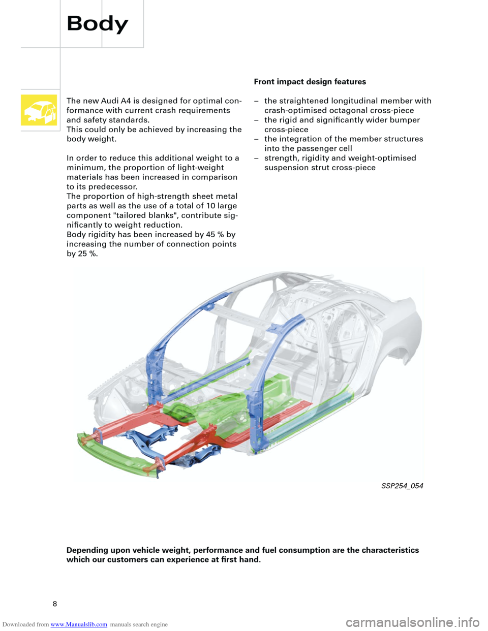
Front impact design features
– the straightened longitudinal member with
crash-optimised octagonal cross-piece
– the rigid and significantly wider bumper
cross-piece
– the integration of the member structures
into the passenger cell
– strength, rigidity and weight-optimised
suspension strut cross-piece The new Audi A4 is designed for optimal con-
formance with current crash requirements
and safety standards.
This could only be achieved by increasing the
body weight.
In order to reduce this additional weight to a
minimum, the proportion of light-weight
materials has been increased in comparison
to its predecessor.
The proportion of high-strength sheet metal
parts as well as the use of a total of 10 large
component "tailored blanks", contribute sig-
nificantly to weight reduction.
Body rigidity has been increased by 45 % by
increasing the number of connection points
by 25 %.
Depending upon vehicle weight, performance and fuel consumption are the characteristics
which our customers can experience at first hand.
SSP254_054
Page 17 of 88
Downloaded from www.Manualslib.com manuals search engine
17
Crash signal processing
There are two separate crash signal outputs:
One crash signal is output via the conven-
tional wiring and triggers the following func-
tions:
– Transmitting an emergency call via the
control unit for telephone/telematics J526
(optional)
– unlocking the vehicle,
– Switch on interior light
(switch must be set to door contact),
– switching on hazard warning lights via the
central convenience electronics J393.
The auxiliary heater J162 (optional) is
switched off by the central convenience
electronics J393 via a CAN convenience
message.
The second crash signal output functions via
the convenience CAN bus, which switches off
the engine fuel supply via the engine control
unit J220.
Page 20 of 88

Downloaded from www.Manualslib.com manuals search engine
20
Engine and gearbox
In order to initiate pre-injection for cold and
warm engines, the solenoid valve dynamics
have been significantly increased.
The associated increased heat generation in
the solenoid valve, is compensated by
improved fuel flow and optimal filling of the
high pressure section is achieved.
Noise levels have been significantly improved
by the pre-injection for cold and warm opera-
tion and the use of dual-spring nozzle hold-
ers.
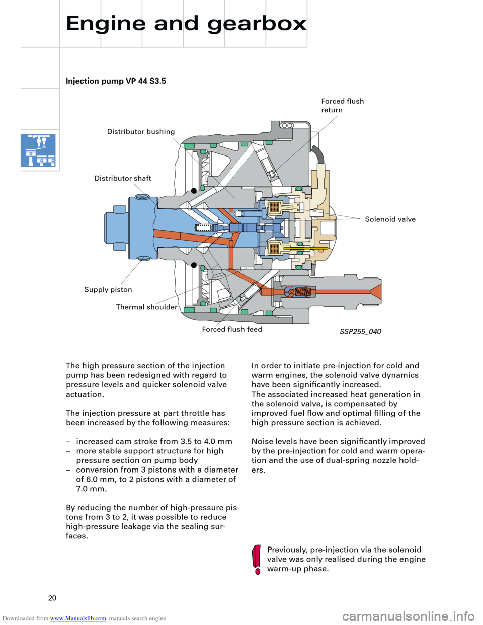
Injection pump VP 44 S3.5
Previously, pre-injection via the solenoid
valve was only realised during the engine
warm-up phase. The high pressure section of the injection
pump has been redesigned with regard to
pressure levels and quicker solenoid valve
actuation.
The injection pressure at part throttle has
been increased by the following measures:
– increased cam stroke from 3.5 to 4.0 mm
– more stable support structure for high
pressure section on pump body
– conversion from 3 pistons with a diameter
of 6.0 mm, to 2 pistons with a diameter of
7.0 mm.
By reducing the number of high-pressure pis-
tons from 3 to 2, it was possible to reduce
high-pressure leakage via the sealing sur-
faces.
Forced flush
return
Distributor bushing
Distributor shaft
Supply piston
Thermal shoulder
Forced flush feed
Solenoid valve
SSP255_040
Page 42 of 88
Downloaded from www.Manualslib.com manuals search engine
42
The Audi A4 quattro is equipped with two fuel
gauge senders G and G169.
Sender G registers the lower, and sender
G169 the upper partial volume in the fuel
tank.
The signals from senders G and G169 are
evaluated separately. The calculated litre
values are then added and displayed. A new feature of the Auto-Check system
is the position-dependent bulb monitor display.
The fault message is transmitted from the vehi-
cle electrical system control unit J519, via the
convenience data bus, to the dash panel insert
J285 and appears on the centre display.
Electrical system
Fuel gauge
sender 2, G169 Fuel gauge
sender G
SSP254_123
Control unit with
display unit in dash
panel processor J285
Control unit for vehicle
electrical system J519 Convenience data
bus
SSP254_118
SSP254_125
Page 43 of 88

Downloaded from www.Manualslib.com manuals search engine
43
A further innovation is the display of the max-
imum and minimum engine oil levels in the
measured value block after the most recent
service operation.
The adaptation of the mileage/kilometre read-
ing after replacement of the dash panel
insert, is possible (several attempts) up to a
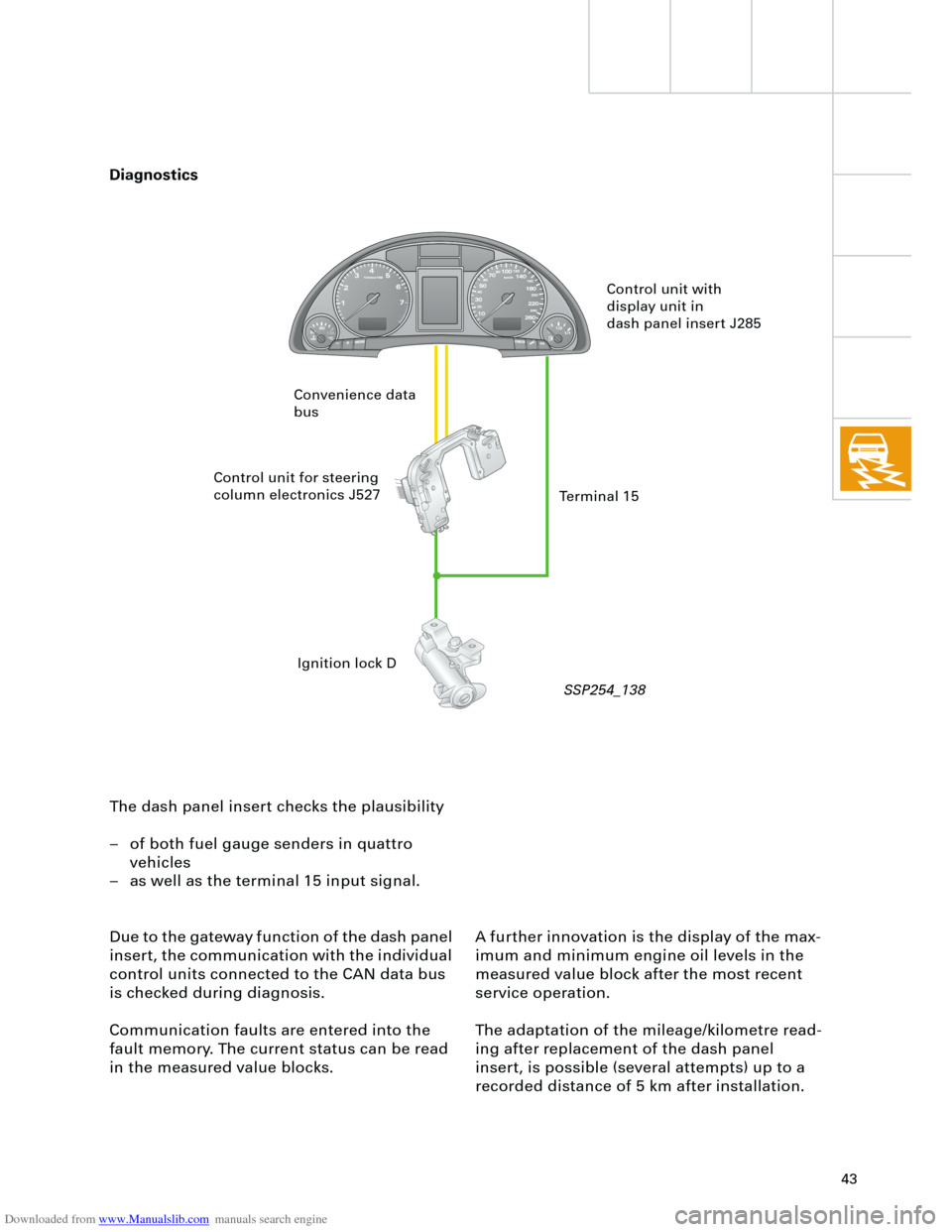
recorded distance of 5 km after installation. The dash panel insert checks the plausibility
– of both fuel gauge senders in quattro
vehicles
– as well as the terminal 15 input signal.
Due to the gateway function of the dash panel
insert, the communication with the individual
control units connected to the CAN data bus
is checked during diagnosis.
Communication faults are entered into the
fault memory. The current status can be read
in the measured value blocks.
Control unit with
display unit in
dash panel insert J285
Control unit for steering
column electronics J527
Ignition lock D Convenience data
bus
Terminal 15
Diagnostics
SSP254_138
Page 59 of 88

Downloaded from www.Manualslib.com manuals search engine
59
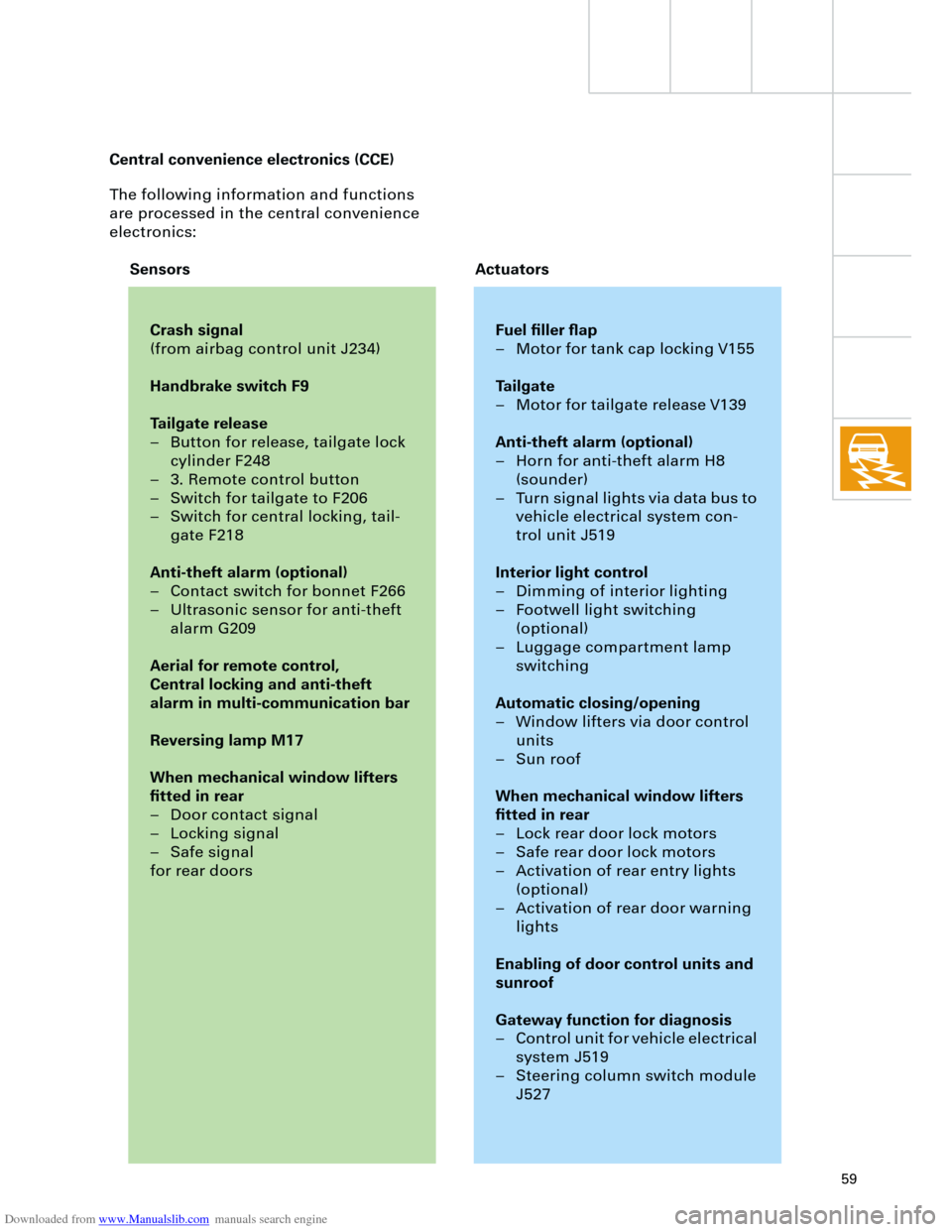
The following information and functions
are processed in the central convenience
electronics:
Crash signal
(from airbag control unit J234)
Handbrake switch F9
Tailgate release
– Button for release, tailgate lock
cylinder F248
– 3. Remote control button
– Switch for tailgate to F206
– Switch for central locking, tail-
gate F218
Anti-theft alarm (optional)
– Contact switch for bonnet F266
– Ultrasonic sensor for anti-theft
alarm G209
Aerial for remote control,
Central locking and anti-theft
alarm in multi-communication bar
Reversing lamp M17
When mechanical window lifters
fitted in rear
– Door contact signal
– Locking signal
– Safe signal
for rear doors
Fuel filler flap
– Motor for tank cap locking V155
Tailgate
– Motor for tailgate release V139
Anti-theft alarm (optional)
– Horn for anti-theft alarm H8
(sounder)
– Turn signal lights via data bus to
vehicle electrical system con-
trol unit J519
Interior light control
– Dimming of interior lighting
– Footwell light switching
(optional)
– Luggage compartment lamp
switching
Automatic closing/opening
– Window lifters via door control
units
– Sun roof
When mechanical window lifters
fitted in rear
– Lock rear door lock motors
– Safe rear door lock motors
– Activation of rear entry lights
(optional)
– Activation of rear door warning
lights
Enabling of door control units and
sunroof
Gateway function for diagnosis
– Control unit for vehicle electrical
system J519
– Steering column switch module
J527
Sensors Actuators Central convenience electronics (CCE)
Page 86 of 88
Downloaded from www.Manualslib.com manuals search engine
86
+ -
K
Additional heater
Heater/AC
The Audi A4 can optionally be equipped with
an additional heater for coolant.
Its mode of operation corresponds to the
systems in use previously.
The additional heater warms the heating-
system heat exchanger in the air conditioner
unit via the cooling-water circuit.
The cut-in time is ”programmed” via the dash
panel insert.
Flame sensor
Fan
driveDiffuser
Fuel tank Combus-
tion air Control and heater
unit for heating
system J162
Heating system
heat exchanger
Exhaust
gas Combustion chamber Glow plug
Fuel pump
SSP254_023
SSP254_097