2000 YAMAHA YZF1000 lock
[x] Cancel search: lockPage 29 of 103

INSTRUMENT AND CONTROL FUNCTIONS
3-15
3
EAU01688
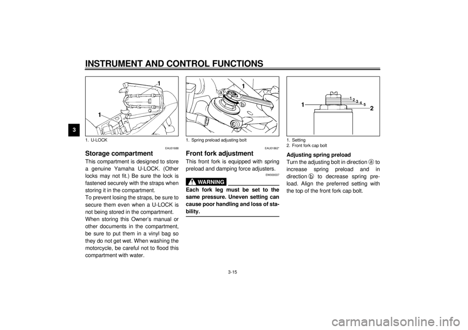
Storage compartmentThis compartment is designed to store
a genuine Yamaha U-LOCK. (Other
locks may not fit.) Be sure the lock is
fastened securely with the straps when
storing it in the compartment.
To prevent losing the straps, be sure to
secure them even when a U-LOCK is
not being stored in the compartment.
When storing this Owner’s manual or
other documents in the compartment,
be sure to put them in a vinyl bag so
they do not get wet. When washing the
motorcycle, be careful not to flood this
compartment with water.
EAU01862*
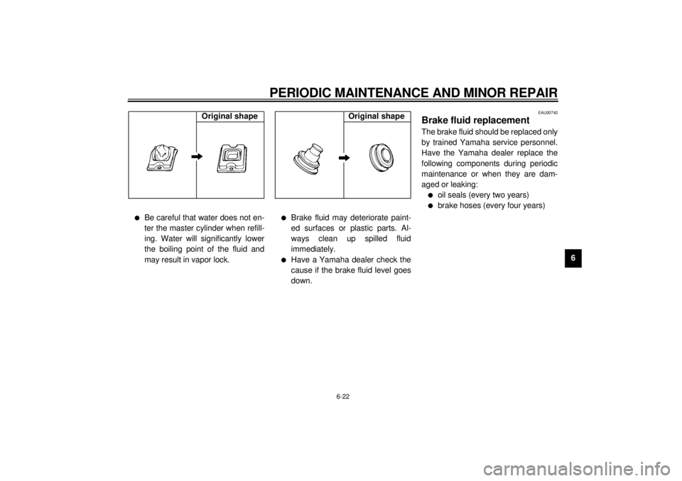
Front fork adjustmentThis front fork is equipped with spring
preload and damping force adjusters.
EW000037
WARNING
@ Each fork leg must be set to the
same pressure. Uneven setting can
cause poor handling and loss of sta-
bility. @
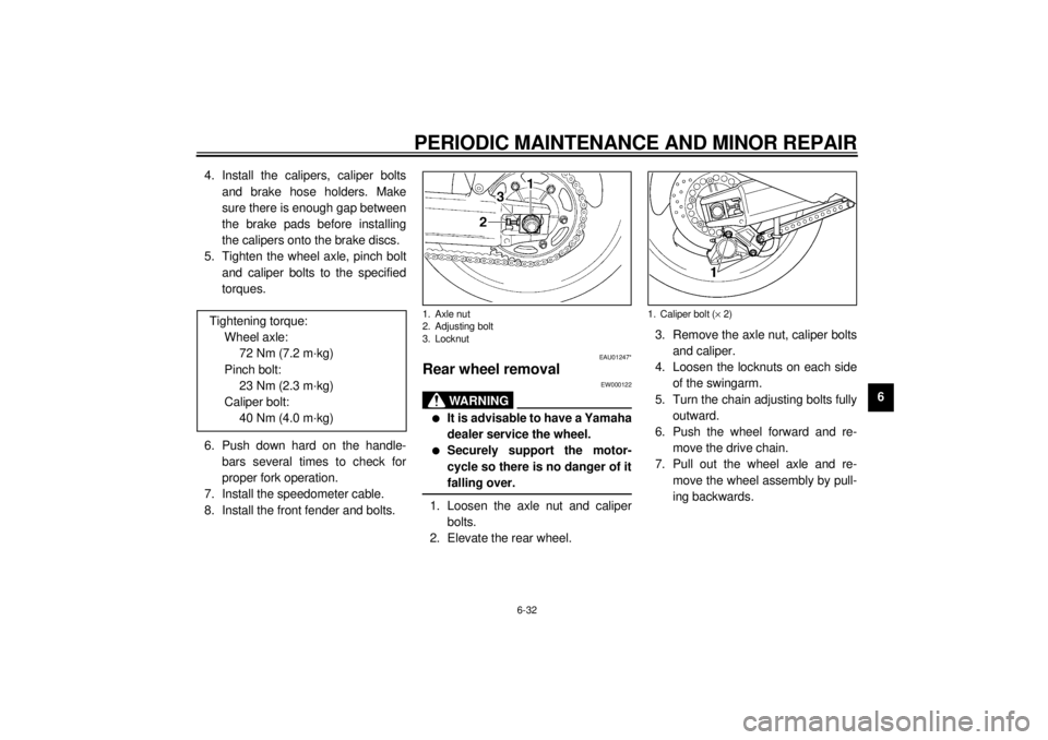
Adjusting spring preload
Turn the adjusting bolt in direction a
to
increase spring preload and in
directionb
to decrease spring pre-
load. Align the preferred setting with
the top of the front fork cap bolt.
1. U-LOCK
1. Spring preload adjusting bolt
1. Setting
2. Front fork cap bolt
E_4sv_Functions.fm Page 15 Tuesday, August 31, 1999 3:42 PM
Page 33 of 103

INSTRUMENT AND CONTROL FUNCTIONS
3-19
3
EAU00324
Luggage strap holdersThere are four luggage strap holders
below the passenger seat, two of which
can be turned outward for easier ac-
cess.
EAU01571
EXUP (EXhaust Ultimate
Powervalve)This model is equipped with Yamaha’s
EXUP system within the exhaust pipe.
This valve is always activated by a
computer-controlled servomotor in ac-
cordance with engine rpm.
EC000027
CAUTION:@ l
The EXUP was set at the
Yamaha factory after many
tests. If the settings are
changed by someone without
sufficient technical knowledge,
poor engine performance and
damage may result.
l
If the EXUP does not operate,
ask a Yamaha dealer to inspect.
@
EAU00330
SidestandThis model is equipped with an ignition
circuit cut-off system. The motorcycle
must not be ridden when the sidestand
is down. The sidestand is located on
the left side of the frame. (Refer to
page 5-1 for an explanation of this sys-
tem.)
EW000044
WA R N I N G
@ This motorcycle must not be operat-
ed with the sidestand in the down
position. If the stand is not properly
retracted, it could contact the
ground and distract the operator, re-
sulting in a possible loss of control.
Yamaha has designed into this
motorcycle a lockout system to as-
sist the operator in fulfilling the re-
sponsibility of retracting the
sidestand. Please check carefully
the operating instructions listed be-
low and if there is any indication of a
malfunction, return the motorcycle
to a Yamaha dealer immediately for
repair. @
1. Luggage strap holder (´ 4)E_4sv_Functions.fm Page 19 Tuesday, August 31, 1999 3:42 PM
Page 70 of 103

PERIODIC MAINTENANCE AND MINOR REPAIR
6-22
6
l
Be careful that water does not en-
ter the master cylinder when refill-
ing. Water will significantly lower
the boiling point of the fluid and
may result in vapor lock.
l
Brake fluid may deteriorate paint-
ed surfaces or plastic parts. Al-
ways clean up spilled fluid
immediately.
l
Have a Yamaha dealer check the
cause if the brake fluid level goes
down.
EAU00742
Brake fluid replacementThe brake fluid should be replaced only
by trained Yamaha service personnel.
Have the Yamaha dealer replace the
following components during periodic
maintenance or when they are dam-
aged or leaking:l
oil seals (every two years)
l
brake hoses (every four years)
Original shape
Original shape
E_4sv_Periodic.fm Page 22 Tuesday, August 31, 1999 3:45 PM
Page 71 of 103

PERIODIC MAINTENANCE AND MINOR REPAIR
6-23
6
EAU00744
Drive chain slack checkNOTE:@ Spin the wheel several times and find
the tightest position of the chain. Check
and/or adjust the chain slack while it’s
in this tightest position. @To check the chain slack the motor-
cycle must be held straight up with both
wheels on the ground and without rider.
Check the slack at the position shown
in the illustration. Normal slack is ap-
proximately 20 ~ 35 mm. If the slack
exceeds 35 mm, adjust.
EAU01251
Drive chain slack adjustment1. Loosen the axle nut.
2. Loosen the locknuts on each side.
To tighten the chain, turn the chain
adjusting bolts in direction a
. To
loosen the chain, turn the adjust-
ing bolts in direction b
and push
the wheel forward. Turn each ad-
justing bolt exactly the same
amount to maintain correct axle
alignment. There are marks oneach side of the swingarm. Use
these marks to align the rear
wheel.
EC000096
CAUTION:@ Too little chain slack will overload
the engine and other vital parts.
Keep the slack within the specified
limits. @3. After adjusting, tighten the lock-
nuts. Then tighten the axle nut to
the specified torque.
a. Drive chain slack
1. Axle nut
2. Adjusting bolt
3. Locknut
4. Alignment marks
Tightening torque:
Axle nut:
150 Nm (15 m·kg)
E_4sv_Periodic.fm Page 23 Tuesday, August 31, 1999 3:45 PM
Page 78 of 103

PERIODIC MAINTENANCE AND MINOR REPAIR
6-30
6
EC000105
CAUTION:@ Avoid touching the glass part of a
bulb. Keep it free from oil; other-
wise, the transparency of the glass,
life of the bulb, and luminous flux
will be adversely affected. If oil gets
on a bulb, thoroughly clean it with a
cloth moistened with alcohol or lac-
quer thinner. @4. Install the bulb holder cover and
reconnect the headlight connec-
tors. If the headlight beam adjust-
ment is necessary, ask a Yamaha
dealer to make that adjustment.
EAU01823*
Tail/brake light bulb
replacement1. Remove the passenger seat. (See
page 3-14 for seat removal and in-
stallation procedures.)
2. To remove the socket, turn it coun-
terclockwise.
3. To remove the defective bulb, turn
it counterclockwise.
4. Push a new bulb into the socket
and turn it clockwise.
5. Install the socket and turn it clock-
wise.
6. Install the passenger seat.
EAU01095
Turn signal light bulb
replacement1. Remove the screw and the lens.
2. Remove the defective bulb by
pushing it inward and turning it
counterclockwise.
3. Install a new bulb by pushing it in-
ward and turning it clockwise.
4. Install the lens and tighten the
screw.
1. Don’t touch
1. Screw
E_4sv_Periodic.fm Page 30 Tuesday, August 31, 1999 3:45 PM
Page 80 of 103

PERIODIC MAINTENANCE AND MINOR REPAIR
6-32
6 4. Install the calipers, caliper bolts
and brake hose holders. Make
sure there is enough gap between
the brake pads before installing
the calipers onto the brake discs.
5. Tighten the wheel axle, pinch bolt
and caliper bolts to the specified
torques.
6. Push down hard on the handle-
bars several times to check for
proper fork operation.
7. Install the speedometer cable.
8. Install the front fender and bolts.
EAU01247*
Rear wheel removal
EW000122
WA R N I N G
@ l
It is advisable to have a Yamaha
dealer service the wheel.
l
Securely support the motor-
cycle so there is no danger of it
falling over.
@1. Loosen the axle nut and caliper
bolts.
2. Elevate the rear wheel.3. Remove the axle nut, caliper bolts
and caliper.
4. Loosen the locknuts on each side
of the swingarm.
5. Turn the chain adjusting bolts fully
outward.
6. Push the wheel forward and re-
move the drive chain.
7. Pull out the wheel axle and re-
move the wheel assembly by pull-
ing backwards. Tightening torque:
Wheel axle:
72 Nm (7.2 m·kg)
Pinch bolt:
23 Nm (2.3 m·kg)
Caliper bolt:
40 Nm (4.0 m·kg)1. Axle nut
2. Adjusting bolt
3. Locknut
1. Caliper bolt (´ 2)
E_4sv_Periodic.fm Page 32 Tuesday, August 31, 1999 3:45 PM
Page 84 of 103

PERIODIC MAINTENANCE AND MINOR REPAIR
6-36
6
Engine overheating
EW000070
WARNING
@ Do not remove the radiator cap when the engine and radiator are hot. Scalding hot fluid and steam may be blown
out under pressure, which could cause serious injury. Open the radiator cap as follows. Wait until the engine has
cooled. Remove the radiator cap stopper by removing the screw. Place a thick rag like a towel over the radiator cap
and slowly rotate the cap counterclockwise to the detent. This procedure allows any residual pressure to escape.
When the hissing sound has stopped, press down on the cap while turning counterclockwise and remove it. @NOTE:@ If it is difficult to get the recommended coolant, tap water can be temporarily used, provided that it is changed to the recom-
mended coolant as soon as possible. @
Wait until the
engine has cooled.
Check the coolant level in the
reservoir tank and/or radiator.
Level is OK.Level is low, check the
cooling system for leakage.
No
leakage.Leakage.
Ask a Yamaha dealer to inspect
and repair the cooling system.Add coolant. (See NOTE.)
Restart the engine. If the engine overheats again, ask a
Yamaha dealer to inspect and repair the cooling system.
E_4sv_Periodic.fm Page 36 Tuesday, August 31, 1999 3:45 PM
Page 101 of 103

10-INDEXAAir filter ..................................................6-12BBattery ................................................... 6-27
Brake and clutch lever lubrication........... 6-25
Brake and shift pedal lubrication ............ 6-24
Brake fluid replacement ......................... 6-22
Brake light switch adjustment ................. 6-19CCable inspection and lubrication ............ 6-24
Carburetor adjustment ...........................6-14
Care.........................................................7-1
Checking the front and rear brake
pads ....................................................6-20
Clutch lever .............................................. 3-9
Controls/Instruments ................................2-3
Coolant ..................................................6-11
Coolant temperature gauge ..................... 3-7
Cowling A ................................................6-5
Cowling B ................................................6-5
Cowling C ................................................6-6
Cowling removal and installation .............. 6-5DDiagnosis device......................................3-7
Dimmer switch .........................................3-8
Drive chain lubrication ............................6-24
Drive chain slack adjustment..................6-23
Drive chain slack check.......................... 6-23EEngine break-in........................................ 5-5
Engine oil ................................................. 6-9
Engine stop switch................................... 3-9
EXUP (EXhaust Ultimate Powervalve)... 3-19FFront brake lever ................................... 3-10
Front fork adjustment............................. 3-15
Front fork inspection .............................. 6-26
Front wheel installation .......................... 6-31
Front wheel removal .............................. 6-31
Fuel ....................................................... 3-12
Fuel indicator circuit check....................... 3-5
Fuel indicator light ................................... 3-4
Fuel tank breather hose
(for Germany only) .............................. 3-13
Fuel tank cap ......................................... 3-11
Fuse replacement.................................. 6-28GGive safety the right of way ..................... 1-1HHandlebar switches ................................. 3-8
Dimmer switch ................................... 3-8
Engine stop switch ............................. 3-9
Horn switch ........................................ 3-8
Lights switch ...................................... 3-9
Pass switch ........................................ 3-8
Start switch ........................................ 3-9
Turn signal switch .............................. 3-8
Headlight bulb replacement ................... 6-29
Helmet holder ........................................ 3-14
High beam indicator light ......................... 3-2
Horn switch ............................................. 3-8
IIdentification number records ...................9-1
Idle speed adjustment ............................6-15
Indicator lights ..........................................3-2
Fuel indicator light...............................3-4
High beam indicator light ....................3-2
Neutral indicator light ..........................3-2
Oil level indicator light .........................3-2
Turn indicator light ..............................3-2
Inspecting the brake fluid level ...............6-21KKey identification number .........................9-1LLeft view...................................................2-1
Lights switch ............................................3-9
Luggage strap holders ...........................3-19MMain switch/steering lock .........................3-1
Model label ..............................................9-2NNeutral indicator light ...............................3-2OOil level indicator circuit check .................3-3
Oil level indicator light ..............................3-2PParking.....................................................5-6
Pass switch ..............................................3-8
Periodic maintenance and lubrication .......6-2
Pre-operation check list............................. 4-1
E_4svIX.fm Page 1 Tuesday, August 31, 1999 3:49 PM