Page 272 of 442
4 - 47
ENGCLUTCH AND PRIMARY DRIVEN GEAR
5. Install:
lBall
NOTE:
Apply the engine oil on the ball.
6. Install:
lPush rod 1 1
lPush plate 2
lWasher 3
lNut (push rod 1) 4
7. Install:
lPressure plate 1
lClutch spring 2
lBolt (clutch spring) 3
NOTE:
lAlign the arrow mark a on the pressure
plate with the punched mark b on the clutch
boss.
lTighten the bolts in stage, using a crisscross
pattern.
T R..6 Nm (0.6 m · kg, 4.3 ft · lb)
8. Check:
lPush lever position
Push the push lever assembly in the
arrow direction and make sure that the
mach mark are aligned ® adjust.
aMatch mark on the push lever assembly
bMatch mark on the crankcase
Page 274 of 442
4 - 48
ENGCLUTCH AND PRIMARY DRIVEN GEAR
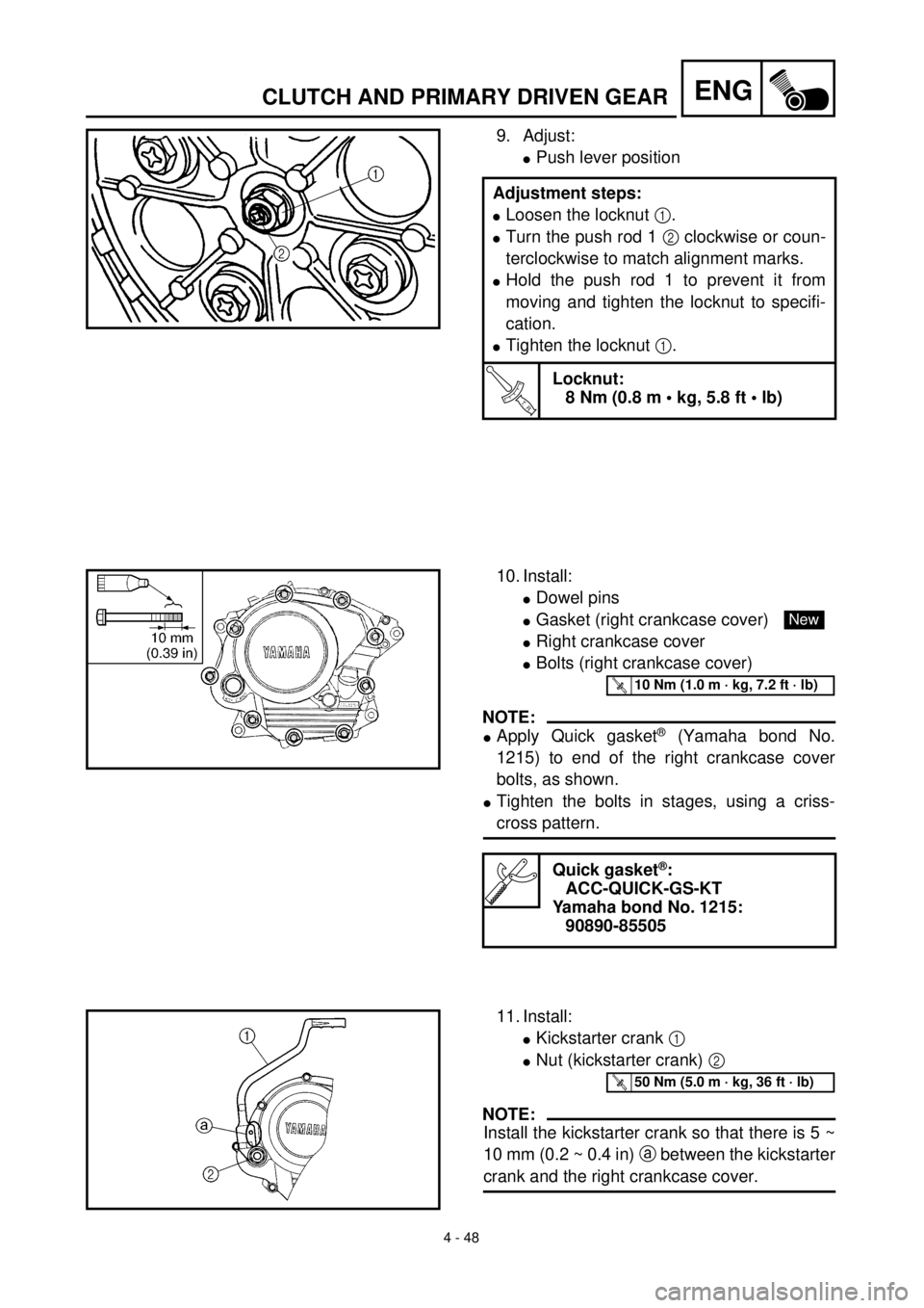
9. Adjust:
lPush lever position
Adjustment steps:
lLoosen the locknut 1.
lTurn the push rod 1 2 clockwise or coun-
terclockwise to match alignment marks.
lHold the push rod 1 to prevent it from
moving and tighten the locknut to specifi-
cation.
lTighten the locknut 1.
T R..
Locknut:
8 Nm (0.8 m • kg, 5.8 ft • lb)
10. Install:
lDowel pins
lGasket (right crankcase cover)
lRight crankcase cover
lBolts (right crankcase cover)
NOTE:
lApply Quick gasket® (Yamaha bond No.
1215) to end of the right crankcase cover
bolts, as shown.
lTighten the bolts in stages, using a criss-
cross pattern.
Quick gasket®:
ACC-QUICK-GS-KT
Yamaha bond No. 1215:
90890-85505
New
T R..10 Nm (1.0 m · kg, 7.2 ft · lb)
11. Install:
lKickstarter crank 1
lNut (kickstarter crank) 2
NOTE:
Install the kickstarter crank so that there is 5 ~
10 mm (0.2 ~ 0.4 in) a between the kickstarter
crank and the right crankcase cover.
T R..50 Nm (5.0 m · kg, 36 ft · lb)
Page 276 of 442
4 - 49
ENGOIL PUMP
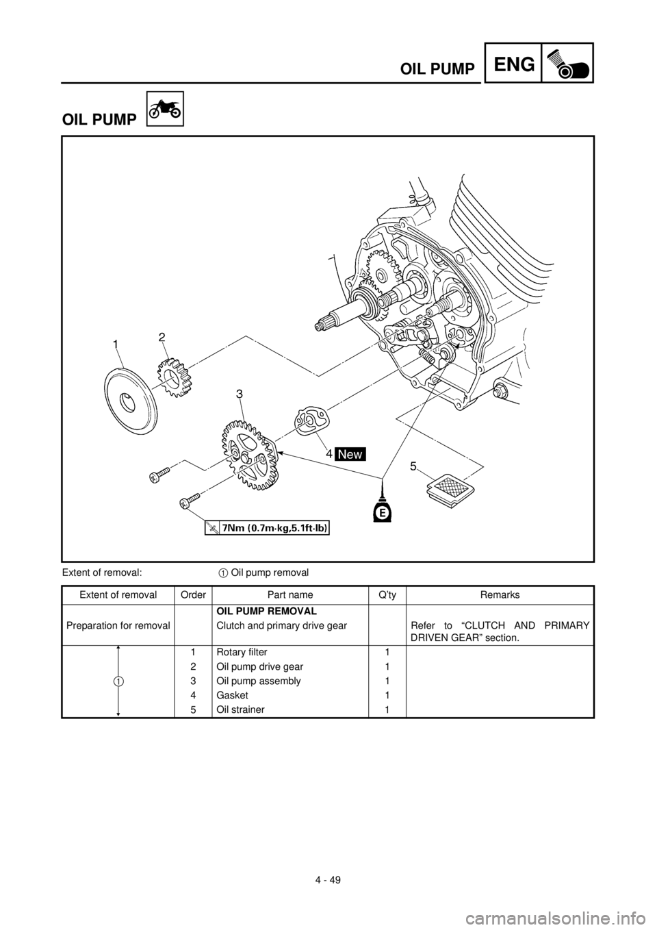
OIL PUMP
Extent of removal:1 Oil pump removal
Extent of removal Order Part name Q’ty Remarks
OIL PUMP REMOVAL
Preparation for removal Clutch and primary drive gear Refer to “CLUTCH AND PRIMARY
DRIVEN GEAR” section.
1 Rotary filter 1
2 Oil pump drive gear 1
3 Oil pump assembly 1
4 Gasket 1
5Oil strainer
1
1
Page 284 of 442
4 - 53
ENGKICK AXLE AND SHIFT SHAFT
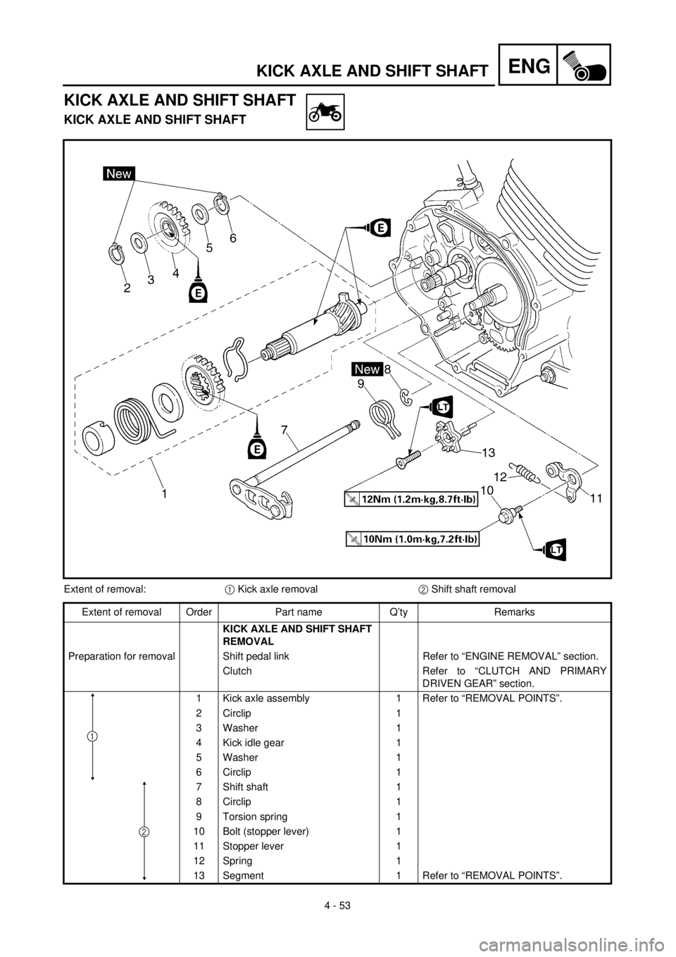
KICK AXLE AND SHIFT SHAFT
KICK AXLE AND SHIFT SHAFT
Extent of removal:1 Kick axle removal2 Shift shaft removal
Extent of removal Order Part name Q’ty Remarks
KICK AXLE AND SHIFT SHAFT
REMOVAL
Preparation for removal Shift pedal link Refer to “ENGINE REMOVAL” section.
Clutch Refer to “CLUTCH AND PRIMARY
DRIVEN GEAR” section.
1 Kick axle assembly 1 Refer to “REMOVAL POINTS”.
2 Circlip 1
3 Washer 1
4 Kick idle gear 1
5 Washer 1
6 Circlip 1
7 Shift shaft 1
8 Circlip 1
9 Torsion spring 1
10 Bolt (stopper lever) 1
11 Stopper lever 1
12 Spring 1
13 Segment 1 Refer to “REMOVAL POINTS”.
1
2
Page 300 of 442
4 - 61
ENGENGINE REMOVAL
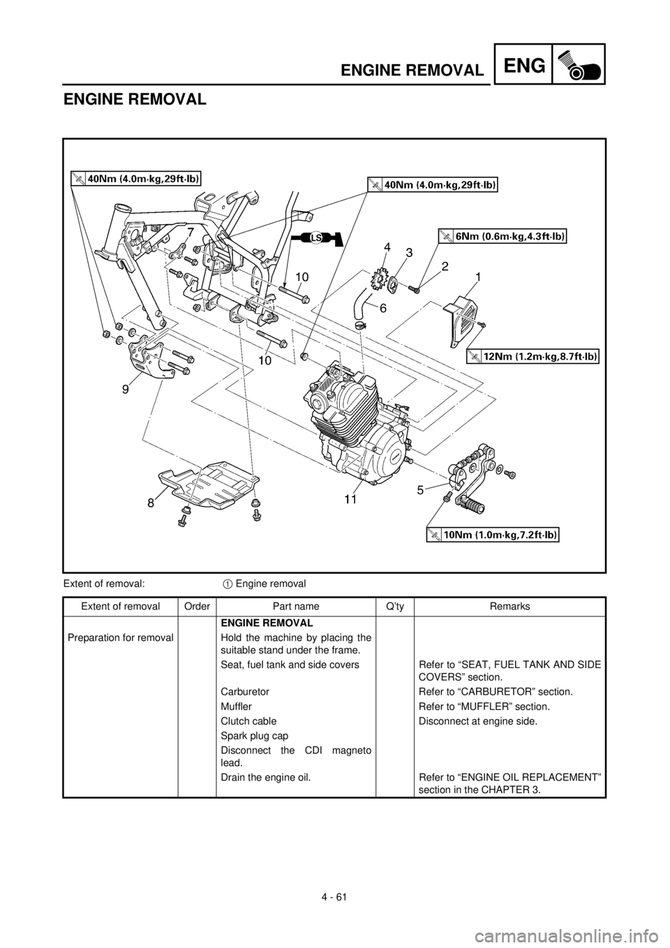
ENGINE REMOVAL
Extent of removal:1 Engine removal
Extent of removal Order Part name Q’ty Remarks
ENGINE REMOVAL
Preparation for removal Hold the machine by placing the
suitable stand under the frame.
Seat, fuel tank and side covers Refer to “SEAT, FUEL TANK AND SIDE
COVERS” section.
Carburetor Refer to “CARBURETOR” section.
Muffler Refer to “MUFFLER” section.
Clutch cable Disconnect at engine side.
Spark plug cap
Disconnect the CDI magneto
lead.
Drain the engine oil. Refer to “ENGINE OIL REPLACEMENT”
section in the CHAPTER 3.
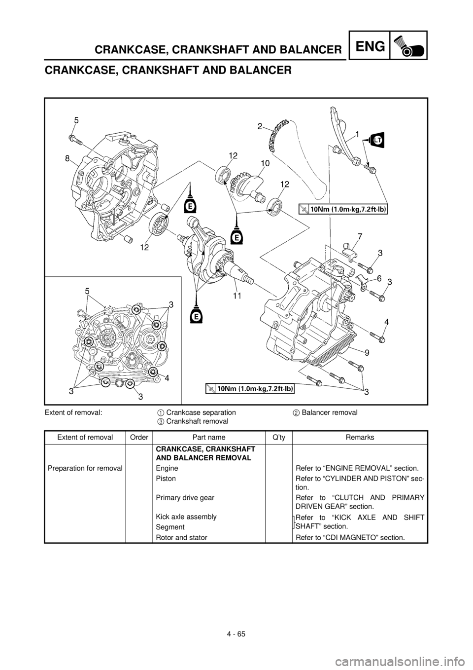
Page 308 of 442
4 - 65
ENGCRANKCASE, CRANKSHAFT AND BALANCER
CRANKCASE, CRANKSHAFT AND BALANCER
Extent of removal:1 Crankcase separation2 Balancer removal
3 Crankshaft removal
Extent of removal Order Part name Q’ty Remarks
CRANKCASE, CRANKSHAFT
AND BALANCER REMOVAL
Preparation for removal Engine Refer to “ENGINE REMOVAL” section.
Piston Refer to “CYLINDER AND PISTON” sec-
tion.
Primary drive gear Refer to “CLUTCH AND PRIMARY
DRIVEN GEAR” section.
Kick axle assembly
Refer to “KICK AXLE AND SHIFT
SHAFT” section.
Segment
Rotor and stator Refer to “CDI MAGNETO” section.
Page 310 of 442
4 - 66
ENGCRANKCASE, CRANKSHAFT AND BALANCER
Extent of removal Order Part name Q’ty Remarks
1 Intake timing chain guide 1
2 Timing chain 1
3 Bolt [15 mm (0.6 in)] 7
4 Bolt [55 mm (2.2 in)] 1
5 Bolt [30 mm (1.2 in)] 2
6 Lead guide 1
7 Clutch cable holder 1
8 Right crankcase 1
Use special tool.
Refer to “REMOVAL POINTS”.
9 Left crankcase 1
10 Balancer 1
11 Crankshaft 1 Use special tool.
Refer to “REMOVAL POINTS”.
12 Bearing 3 Refer to “REMOVAL POINTS”.
3
21
Page 312 of 442

4 - 67
ENGCRANKCASE, CRANKSHAFT AND BALANCER
REMOVAL POINTS
Crankcase
1. Remove:
lBolt (crankcase)
lLead guide 1
lClutch cable holder 2
NOTE:
Loosen each bolt 1/4 of a turn at a time and
after all the bolts are loosened, remove them.
2. Remove:
lRight crankcase 1
Use the crankcase separating tool 2.
NOTE:
lFully tighten the tool holding bolts, but make
sure the tool body is parallel with the case. If
necessary, one screw may be backed out
slightly to level tool body.
lAs pressure is applied, alternately tap on the
front engine mounting boss and transmission
shafts.
CAUTION:
Use soft hammer to tap on the case half.
Tap only on reinforced portions of case. Do
not tap on gasket mating surface. Work
slowly and carefully. Make sure the case
halves separate evenly. If one end “hangs
up”, take pressure off the push screw, re-
align, and start over. If the cases do not
separate, check for a remaining case screw
or fitting. Do not force.
Crankcase separating tool:
YU-01135-A/90890-01135

![YAMAHA TTR125 2000 Betriebsanleitungen (in German) 4 - 66
ENGCRANKCASE, CRANKSHAFT AND BALANCER
Extent of removal Order Part name Q’ty Remarks
1 Intake timing chain guide 1
2 Timing chain 1
3 Bolt [15 mm (0.6 in)] 7
4 Bolt [55 mm (2.2 in)] 1
5 Bolt](/manual-img/51/51652/w960_51652-309.png "YAMAHA TTR125 2000 Betriebsanleitungen (in German) 4 - 66
ENGCRANKCASE, CRANKSHAFT AND BALANCER
Extent of removal Order Part name Q’ty Remarks
1 Intake timing chain guide 1
2 Timing chain 1
3 Bolt [15 mm (0.6 in)] 7
4 Bolt [55 mm (2.2 in)] 1
5 Bolt")