Page 7 of 78

EAU00009
TABLE OF CONTENTS
GIVE SAFETY THE RIGHT OF WAY ..................1-1
DESCRIPTION ....................................................2-1
Left view ............................................................. 2-1
Right view...........................................................2-2
Controls/Instruments ..........................................2-3
INSTRUMENT AND CONTROL FUNCTIONS ....3-1
Main switch/steering lock ................................... 3-1
Indicator lights ....................................................3-2
Speedometer......................................................3-2
Handlebar switches ............................................3-2
Clutch lever ........................................................3-4
Shift pedal ..........................................................3-4
Front brake lever ................................................ 3-4
Rear brake pedal................................................ 3-5
Fuel tank cap......................................................3-5
Fuel ....................................................................3-6
Fuel cock ............................................................3-6
Starter (choke) knob...........................................3-7
Seat ....................................................................3-8
Helmet holder .....................................................3-8
Rear shock absorber adjustment .......................3-9
Sidestand ...........................................................3-9
Sidestand/clutch switch operation check ......... 3-10PRE-OPERATION CHECKS ...............................4-1
Pre-operation check list......................................4-1
OPERATION AND IMPORTANT RIDING
POINTS................................................................5-1
Starting the engine .............................................5-1
Starting a warm engine ......................................5-3
Shifting ...............................................................5-4
Recommended shift points
(for Switzerland only) ......................................5-4
Tips for reducing fuel consumption ....................5-5
Engine break-in ..................................................5-5
Parking ...............................................................5-6
PERIODIC MAINTENANCE AND MINOR
REPAIR................................................................6-1
Tool kit................................................................6-1
Periodic maintenance and lubrication chart .......6-2
Panel removal and installation ...........................6-5
Panels A and B ..................................................6-5
Spark plug ..........................................................6-6
Engine oil ...........................................................6-8
Air filter .............................................................6-10
Carburetor adjustment .....................................6-11
Idle speed adjustment ......................................6-11
123
456
E_3mw.book Page 1 Monday, February 5, 2001 9:54 AM
Page 12 of 78
DESCRIPTION
2-3
2
Controls/Instruments1. Clutch lever (page 3-4)
2. Left handlebar switches (page 3-2)
3. Speedometer (page 3-2)
4. Front brake fluid reservoir (page 6-20)5. Right handlebar switches (page 3-3)
6. Front brake lever (page 3-4)
7. Throttle grip (page 6-12)
8. Main switch/steering lock (page 3-1)
E_3mw.book Page 3 Monday, February 5, 2001 9:54 AM
Page 13 of 78

3-1
3
EAU00027
3-INSTRUMENT AND CONTROL FUNCTIONS
EAU00029*
Main switch/steering lockThe main switch controls the ignition
and lighting systems. Its operation is
described below.
EAU00036
ON
Electrical circuits are switched on. The
engine can be started. The key cannot
be removed in this position.
EAU00038
OFF
All electrical circuits are switched off.
The key can be removed in this posi-
tion.
EAU00040
LOCK
The steering is locked in this position
and all electrical circuits are switched
off. The key can be removed in this po-
sition.
To lock the steering, turn the handle-
bars all the way to the left. While push-
ing the key into the main switch, turn it
from “OFF” to “LOCK” and remove it.
To release the lock, turn the key to
“OFF” while pushing.
EW000016
WARNING
@ Never turn the key to “OFF” or
“LOCK” when the motorcycle is
moving. The electrical circuits will
be switched off which may result in
loss of control or an accident. Be
sure the motorcycle is stopped be-
fore turning the key to “OFF” or
“LOCK”. @1. Push
2. Turn
E_3mw.book Page 1 Monday, February 5, 2001 9:54 AM
Page 17 of 78
INSTRUMENT AND CONTROL FUNCTIONS
3-5
3
EAU00162
Rear brake pedalThe rear brake pedal is on the right
side of the motorcycle. Press down on
the brake pedal to apply the rear brake.
EAU00167
Fuel tank capTo open
Insert the key and turn it 1/4 turn clock-
wise. The lock will be released and the
cap can be opened.
To close
Push the tank cap into position with the
key inserted. To remove the key, turn it
counterclockwise to the original posi-
tion.
NOTE:@ This tank cap cannot be closed unless
the key is in the lock. The key cannot
be removed if the cap is not locked
properly. @
EW000023
WARNING
@ Be sure the cap is properly installed
and locked in place before riding the
motorcycle. @
1. Rear brake pedal
1. Open
E_3mw.book Page 5 Monday, February 5, 2001 9:54 AM
Page 20 of 78
INSTRUMENT AND CONTROL FUNCTIONS
3-8
3
EAU01092
SeatTo remove the seat, remove the bolts.To install the seat, insert the projection
on the front of the seat into the holder
and push down on the seat, then tight-
en the bolts.
NOTE:@ Make sure that the seat is securely fit-
ted. @
EAU00261
Helmet holderTo open the helmet holder, insert the
key in the lock and turn it as shown.
To lock the helmet holder, turn the key
to its original position.
EW000030
WARNING
@ Never ride with a helmet in the hel-
met holder. The helmet may hit ob-
jects, causing loss of control and
possibly an accident. @
1. Bolt (´ 2)
1. Seat holder
2. Projection
1. Lock
2. Open
E_3mw.book Page 8 Monday, February 5, 2001 9:54 AM
Page 21 of 78

INSTRUMENT AND CONTROL FUNCTIONS
3-9
3
EAU00300
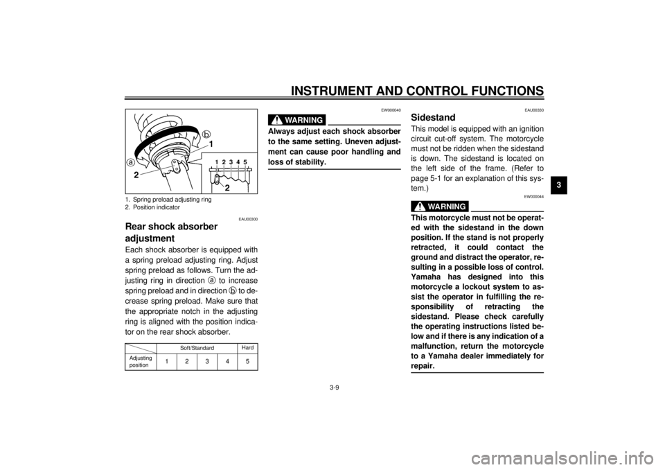
Rear shock absorber
adjustmentEach shock absorber is equipped with
a spring preload adjusting ring. Adjust
spring preload as follows. Turn the ad-
justing ring in direction
a to increase
spring preload and in direction
b to de-
crease spring preload. Make sure that
the appropriate notch in the adjusting
ring is aligned with the position indica-
tor on the rear shock absorber.CI-15EEW000040
WARNING
@ Always adjust each shock absorber
to the same setting. Uneven adjust-
ment can cause poor handling and
loss of stability. @
EAU00330
SidestandThis model is equipped with an ignition
circuit cut-off system. The motorcycle
must not be ridden when the sidestand
is down. The sidestand is located on
the left side of the frame. (Refer to
page 5-1 for an explanation of this sys-
tem.)
EW000044
WARNING
@ This motorcycle must not be operat-
ed with the sidestand in the down
position. If the stand is not properly
retracted, it could contact the
ground and distract the operator, re-
sulting in a possible loss of control.
Yamaha has designed into this
motorcycle a lockout system to as-
sist the operator in fulfilling the re-
sponsibility of retracting the
sidestand. Please check carefully
the operating instructions listed be-
low and if there is any indication of a
malfunction, return the motorcycle
to a Yamaha dealer immediately for
repair. @
1. Spring preload adjusting ring
2. Position indicator
Soft/StandardHard
Adjusting
position
12345
E_3mw.book Page 9 Monday, February 5, 2001 9:54 AM
Page 42 of 78
PERIODIC MAINTENANCE AND MINOR REPAIR
6-12
6
EAU00634
Throttle cable free play
adjustmentNOTE:@ Before checking the throttle cable free
play, the engine idling speed should be
adjusted. @Adjust the throttle cable by turning the
adjusting nut so that specified free play
at the throttle grip is obtained.1. Loosen the locknut.
2. Turn the adjusting nut in
direction
a to increase free play
and in direction
b to decrease
free play.
3. Tighten the locknut.
EAU00636
Cam chain adjustmentThe cam chain becomes loose with
use, resulting in improper valve timing
and engine noise. To prevent this, the
cam chain tensioner must be adjusted
regularly. This adjustment, however,
should be left to a professional
Yamaha service technician.
a. Free playFree play:
3 ~ 5 mm
1. Adjusting nut
2. Locknut
E_3mw.book Page 12 Monday, February 5, 2001 9:54 AM
Page 46 of 78
PERIODIC MAINTENANCE AND MINOR REPAIR
6-16
6
EAU00692
Clutch lever free play
adjustmentThe clutch lever free play should be ad-
justed to 10 ~ 15 mm. If the free play is
incorrect, adjust as follows.
1. Loosen the locknut.
2. Turn the adjusting bolt at the
clutch lever in direction
a to in-
crease free play or in direction
b
to decrease free play.
3. Tighten the locknut.
NOTE:@ If proper adjustment cannot be ob-
tained or the clutch does not work cor-
rectly, ask a Yamaha dealer to inspect
the internal clutch mechanism. @
EAU00696
Front brake lever free play
adjustmentThe free play at the front brake lever
should be 2 ~ 5 mm.
1. Loosen the locknut.
2. Turn the adjusting bolt in
direction
a to increase free play
or in direction
b to decrease free
play.
3. After adjusting, tighten the locknut.
1. Locknut
2. Adjusting bolt
c. Free play
1. Locknut
2. Adjusting bolt
c. Free play
E_3mw.book Page 16 Monday, February 5, 2001 9:54 AM