2000 YAMAHA MAJESTY 250 coolant temperature
[x] Cancel search: coolant temperaturePage 15 of 106

12
3
4
5
6
7
8
9
2-3
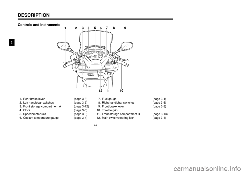
1.Rear brake lever(page 3-8)
2.Left handlebar switches(page 3-5)
3.Front storage compartment A (page 3-12)
4.Clock(page 3-5)
5.Speedometer unit(page 3-3)
6.Coolant temperature gauge (page 3-4)7.Fuel gauge(page 3-4)
8.Right handlebar switches(page 3-6)
9.Front brake lever(page 3-8)
10.Throttle grip
11.Front storage compartment B(page 3-13)
12.Main switch/steering lock(page 3-1)
12345
6789
10
11 12
Controls and instrumentsDESCRIPTION
5GM-9-E1(No ABS) 9/27/00 2:18 PM Page 14
Page 16 of 106

INSTRUMENT AND CONTROL FUNCTIONSMain switch/steering lock....................................................................3-1
Indicator lights....................................................................................3-2
Speedometer unit...............................................................................3-3
Self-diagnosis device .........................................................................3-3
Anti-theft alarm (optional)...................................................................3-4
Fuel gauge..........................................................................................3-4
Coolant temperature gauge................................................................3-4
Clock...................................................................................................3-5
Handlebar switches............................................................................3-5
Front brake lever................................................................................3-8
Rear brake lever.................................................................................3-8
Fuel tank cap......................................................................................3-9
Fuel...................................................................................................3-10
Catalytic converter............................................................................3-10
Rider seat.........................................................................................3-11
Adjusting the rider seat.....................................................................3-12
Storage compartments.....................................................................3-12
Adjusting the shock absorber assemblies........................................3-14
Sidestand..........................................................................................3-15
Ignition circuit cut-off system............................................................3-15
3
5GM-9-E1(No ABS) 9/27/00 2:18 PM Page 15
Page 20 of 106

3-4
INSTRUMENT AND CONTROL FUNCTIONS
1
23
4
5
6
7
8
9
1
EAU00110
Fuel gaugeThe fuel gauge indicates the amount
of fuel in the fuel tank. The needle
moves towards ÒEÓ (Empty) as the
fuel level decreases. When the nee-
dle reaches ÒEÓ, approximately 1.0 L
of fuel remain in the fuel tank. If this
occurs, refuel as soon as possible.NOTE:
Do not allow the fuel tank to empty
itself completely.1.Fuel gauge
1
2
1.Coolant temperature gauge
2.Red mark
EAU03124
Coolant temperature gaugeThis gauge indicates the coolant tem-
perature when the main switch is on.
The engine operating temperature
will vary with changes in weather and
engine load. If the needle points to
the red mark, stop your scooter and
let the engine cool. (See page
6-18 for details.)
EC000002
cCDo not operate the engine if it is
overheated.
EAU00109
Anti-theft alarm (optional)This scooter can be equipped with an
optional anti-theft alarm by a Yamaha
dealer. Contact a Yamaha dealer for
more information.
5GM-9-E1(No ABS) 9/27/00 2:18 PM Page 19
Page 64 of 106

6-20
PERIODIC MAINTENANCE AND MINOR REPAIR
1
2
3
4
56
7
8
9
NOTE:
The radiator fan is automatically
switched on or off according to the
coolant temperature in the radiator. If
the engine overheats, see page 6-40
for further instructions.
Cleaning the air filter element
1.Place the scooter on the center-
stand.
2.Remove the air filter case cover
by removing the screws.
3.Pull the sponge material out
along with the mesh sheet, clean
it with solvent, and then squeeze
the remaining solvent out.
EAU03627
Air filter and V-belt case air
filter elementsThe air filter and V-belt case air filter
elements should be cleaned at the
intervals specified in the periodic
maintenance and lubrication chart.
Clean both filter elements more fre-
quently if you are riding in unusually
wet or dusty areas.
EC000092
cC8Make sure that each filter ele-
ment is properly seated in its
case.
8The engine should never be
operated without the filter ele-
ments installed, otherwise the
piston(s) and/or cylinder(s)
may become excessively
worn.
1
2 2
3
4
1.Air filter case cover
2.Screw (´5)
3.Sponge material
4.Mesh sheet
5GM-9-E1(No ABS) 9/27/00 2:18 PM Page 63
Page 101 of 106

INDEX
F
Final gear oil..........................................6-17
Front and rear brake lever free play,
adjusting.............................................6-25
Front and rear brake pads, checking.....6-26
Front fork, checking...............................6-29
Fuel.......................................................3-10
Fuel consumption, tips for reducing........5-4
Fuel gauge..............................................3-4
Fuel tank cap...........................................3-9
Fuses, replacing....................................6-33
H
Handlebar switches.................................3-5
Pass switch.........................................3-5
Dimmer switch....................................3-5
Turn signal switch...............................3-6
Horn switch.........................................3-6
Light switch.........................................3-6
Headlight variations............................3-7
Engine stop switch..............................3-8
Start switch.........................................3-8
Headlight bulb, replacing.......................6-34
I
Identification numbers.............................9-1
Ignition circuit cut-off system.................3-15
Indicator lights.........................................3-2
Oil change indicator light....................3-2
High beam indicator light....................3-2
Turn signal indicator lights..................3-2
K
Key identification number........................9-1
L
License plate light bulb, replacing.........6-37
M
Main switch/steering lock........................3-1
Model label..............................................9-2
P
Parking....................................................5-5
Part locations...........................................2-1
Periodic maintenance and lubrication
chart......................................................6-3
Pre-operation check list...........................4-1
R
Rider seat..............................................3-11
Rider seat, adjusting..............................3-12
S
Safe-riding points....................................1-2
Self-diagnosis device..............................3-3
Shock absorber assemblies, adjusting..3-14
Sidestand..............................................3-15
Spark plug, checking.............................6-12
Specifications..........................................8-1
Speedometer unit....................................3-3
Starting off...............................................5-2
Starting the engine..................................5-1
Steering, checking.................................6-30
Storage....................................................7-4
A
Acceleration and deceleration.................5-3
Air filter and V-belt case air filter
elements, cleaning..............................6-20
Air flow louver........................................6-22
Anti-theft alarm (optional)........................3-4
B
Battery...................................................6-31
Battery cover, removing........................6-31
Brake fluid level, checking.....................6-27
Brake fluid, changing.............................6-28
Brake lever (front)....................................3-8
Brake lever (rear)....................................3-8
Brake levers, lubricating........................6-28
Braking....................................................5-3
C
Cables, checking and lubricating...........6-28
Care.........................................................7-1
Catalytic converter.................................3-10
Centerstand and sidestand, checking
and lubricating....................................6-29
Clock.......................................................3-5
Conversion table.....................................8-5
Coolant..................................................6-18
Coolant temperature gauge.....................3-4
Cowlings and panel, removing and
installing................................................6-6
E
Engine break-in.......................................5-4
Engine oil...............................................6-14
5GM-9-E1(No ABS) 9/27/00 2:18 PM Page 100