Page 15 of 106
12
3
4
5
6
7
8
9
2-3
1.Rear brake lever(page 3-8)
2.Left handlebar switches(page 3-5)
3.Front storage compartment A (page 3-12)
4.Clock(page 3-5)
5.Speedometer unit(page 3-3)
6.Coolant temperature gauge (page 3-4)7.Fuel gauge(page 3-4)
8.Right handlebar switches(page 3-6)
9.Front brake lever(page 3-8)
10.Throttle grip
11.Front storage compartment B(page 3-13)
12.Main switch/steering lock(page 3-1)
12345
6789
10
11 12
Controls and instrumentsDESCRIPTION
5GM-9-E1(No ABS) 9/27/00 2:18 PM Page 14
Page 16 of 106

INSTRUMENT AND CONTROL FUNCTIONSMain switch/steering lock....................................................................3-1
Indicator lights....................................................................................3-2
Speedometer unit...............................................................................3-3
Self-diagnosis device .........................................................................3-3
Anti-theft alarm (optional)...................................................................3-4
Fuel gauge..........................................................................................3-4
Coolant temperature gauge................................................................3-4
Clock...................................................................................................3-5
Handlebar switches............................................................................3-5
Front brake lever................................................................................3-8
Rear brake lever.................................................................................3-8
Fuel tank cap......................................................................................3-9
Fuel...................................................................................................3-10
Catalytic converter............................................................................3-10
Rider seat.........................................................................................3-11
Adjusting the rider seat.....................................................................3-12
Storage compartments.....................................................................3-12
Adjusting the shock absorber assemblies........................................3-14
Sidestand..........................................................................................3-15
Ignition circuit cut-off system............................................................3-15
3
5GM-9-E1(No ABS) 9/27/00 2:18 PM Page 15
Page 17 of 106

3-1
IGNITION
P
LOCK
ON
OFF
OPENPUSHPUSH
EAU00029
Main switch/steering lockThe main switch/steering lock con-
trols the ignition and lighting systems,
and is used to lock the steering. The
various positions are described
below.
EAU00036
ON
All electrical systems are supplied
with power, and the engine can be
started. The key cannot be removed.
EAU00038
OFF
All electrical systems are off. The key
can be removed.
EAU00040
LOCK
The steering is locked, and all electri-
cal systems are off. The key can be
removed.
To lock the steering1.Turn the handlebars all the way
to the left.
2.Push the key in from the ÒOFFÓ
position, and then turn it to
ÒLOCKÓ while still pushing it.
3.Remove the key.
To unlock the steeringPush the key in, and then turn it to
ÒOFFÓ while still pushing it.
EW000016
wNever turn the key to ÒOFFÓ or
ÒLOCKÓ while the scooter is mov-
ing, otherwise the electrical sys-
tems will be switched off, which
may result in loss of control or an
accident. Make sure that the scoot-
er is stopped before turning the
key to ÒOFFÓ or ÒLOCKÓ.
EAU03733
.
(Parking)
The steering is locked, and the tail-
light, license light and auxiliary light
are on, but all other electrical sys-
tems are off. The key can be
removed.
To turn the main switch to Ò
.
Ó
:
1.Turn the key to ÒLOCKÓ.
2.Slightly turn the key counter-
clockwise until it stops.
3.While still turning the key coun-
terclockwise, push it in until it
snaps into place.
ECA00043
cCDo not use the parking position for
an extended length of time, other-
wise the battery may discharge.
EAU00027
INSTRUMENT AND CONTROL FUNCTIONS
1
23
4
5
6
7
8
95GM-9-E1(No ABS) 9/27/00 2:18 PM Page 16
Page 21 of 106
3-5
INSTRUMENT AND CONTROL FUNCTIONS
1
23
4
5
6
7
8
9
2
3
1
1.Digital clock
2.Hour setting button ÒhÓ
3.Minute setting button ÒmÓ
EAU03800
ClockThe digital clock shows the time
regardless of the main switch posi-
tion.
To set the clock:
1.Turn the key to ÒONÓ.
2.Push or hold the hour setting
button ÒhÓ to change the hours.
3.Push or hold the minute setting
button ÒmÓ to change the min-
utes.
NOTE:
To set the clock after the power
source has been cut, first set the time
to 1:00 AM, and then set the clock to
the correct time.
1
2
3
4
EAU00118
Handlebar switches
EAU00119
Pass switch Ò&
Ó
Press this switch to flash the head-
light.
EAU00121
Dimmer switch
Set this switch to Ò&Ó for the high
beam and to Ò%Ó for the low beam.1.Pass switch Ò&Ó
2.Dimmer switch
3.Turn signal switch
4.Horn switch Ò*Ó
5GM-9-E1(No ABS) 9/27/00 2:18 PM Page 20
Page 25 of 106
3-9
INSTRUMENT AND CONTROL FUNCTIONS
1
23
4
5
6
7
8
9
1
2
EAU03090
Fuel tank capTo open the fuel tank cap
1.Open the lid by sliding the lever
forward, and then pull the lever
up.1.Lid
2.Lever
1
2.Insert the key into the lock and
turn it clockwise. The lock will be
released and the fuel tank cap
can be removed.1.Fuel tank cap
To install the fuel tank cap
1.Align the match marks, insert the
fuel tank cap into the tank open-
ing, and then push down on the
cap.
2.Turn the key counterclockwise to
the original position, and then
remove it.
3.Close the lid.
EWA00028
wBe sure the cap is properly
installed and locked in place
before riding the scooter.
1
1.Match marks
5GM-9-E1(No ABS) 9/27/00 2:18 PM Page 24
Page 27 of 106
3-11
INSTRUMENT AND CONTROL FUNCTIONS
1
23
4
5
6
7
8
9
EC000114
cCThe following precautions must be
observed to prevent a fire hazard
or other damages.
8Use only unleaded gasoline.
The use of leaded gasoline will
cause unrepairable damage to
the catalytic converter.
8Never park the scooter near
possible fire hazards such as
grass or other materials that
easily burn.
8Do not allow the engine to idle
too long.
IGNITION
P
LOCK
ON
OFF
OPENPUSHPUSH
a
a.Open.
EAU03091
Rider seatTo open the rider seat
1.Place the scooter on the center-
stand.
2.Insert the key into the main
switch, and then turn it counter-
clockwise.NOTE:
Do not push inward when turning the
key.
1
3.Fold the rider seat up.
To close the rider seat
1.Fold the rider seat down, and
then push it down to lock it in
place.
2.Remove the key from the main
switch if the scooter will be left
unattended.NOTE:
Make sure that the seat is properly
secured before riding.1.Rider seat
5GM-9-E1(No ABS) 9/27/00 2:18 PM Page 26
Page 28 of 106
3-12
INSTRUMENT AND CONTROL FUNCTIONS
1
23
4
5
6
7
8
9
11
2
2
2.Remove the bolts and collars.
3.Slide the rider seat forward or
backward to the desired position.
4.Install the collars and securely
tighten the bolts.
5.Close the rider seat.1.Bolt (
´4)
2.Collar (´4)
1
2
a
1.Button
2.Lid
a.Lock.
EAU03331
Storage compartmentsFront storage compartment A
To open the storage compartment
when it is locked, insert the key in the
lock, turn it counterclockwise, and
then grasp the lock while pushing the
button in.
To open the storage compartment
when it is unlocked, simply grasp the
lock while pushing the button in.
To lock the storage compartment,
push the lid into the original position,
insert the key in the lock, turn it clock-
wise, and then remove it.Compartment A
1
EAU03096
Adjusting the rider seatThe rider seat can be adjusted as fol-
lows to change the riding position.
1.Open the rider seat. 1.Rider seat
5GM-9-E1(No ABS) 9/27/00 2:18 PM Page 27
Page 77 of 106

2.Remove the blown fuse, and
then install a new fuse of the
specified amperage.
EC000103
cCDo not use a fuse of a higher
amperage rating than recommend-
ed to avoid causing extensive
damage to the electrical system
and possibly a fire.3.Turn the key to ÒONÓ and turn on
the electrical circuit in question to
check if the device operates.
6-33
PERIODIC MAINTENANCE AND MINOR REPAIR
1
2
3
4
56
7
8
94.If the fuse immediately blows
again, have a Yamaha dealer
check the electrical system.
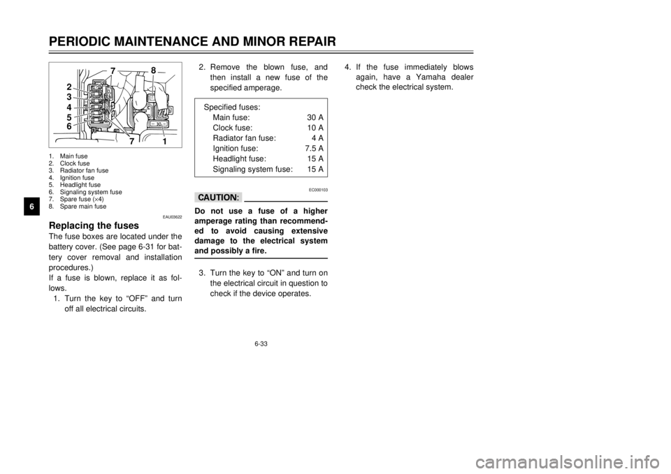
Specified fuses:
Main fuse:30 A
Clock fuse:10 A
Radiator fan fuse:4 A
Ignition fuse:7.5 A
Headlight fuse:15 A
Signaling system fuse:15 A
4
5
67
1
32
78
EAU03622
Replacing the fusesThe fuse boxes are located under the
battery cover. (See page 6-31 for bat-
tery cover removal and installation
procedures.)
If a fuse is blown, replace it as fol-
lows.
1.Turn the key to ÒOFFÓ and turn
off all electrical circuits.1.Main fuse
2.Clock fuse
3.Radiator fan fuse
4.Ignition fuse
5.Headlight fuse
6.Signaling system fuse
7.Spare fuse (´4)
8.Spare main fuse
5GM-9-E1(No ABS) 9/27/00 2:18 PM Page 76