2000 YAMAHA MAJESTY 250 brake light
[x] Cancel search: brake lightPage 16 of 106

INSTRUMENT AND CONTROL FUNCTIONSMain switch/steering lock....................................................................3-1
Indicator lights....................................................................................3-2
Speedometer unit...............................................................................3-3
Self-diagnosis device .........................................................................3-3
Anti-theft alarm (optional)...................................................................3-4
Fuel gauge..........................................................................................3-4
Coolant temperature gauge................................................................3-4
Clock...................................................................................................3-5
Handlebar switches............................................................................3-5
Front brake lever................................................................................3-8
Rear brake lever.................................................................................3-8
Fuel tank cap......................................................................................3-9
Fuel...................................................................................................3-10
Catalytic converter............................................................................3-10
Rider seat.........................................................................................3-11
Adjusting the rider seat.....................................................................3-12
Storage compartments.....................................................................3-12
Adjusting the shock absorber assemblies........................................3-14
Sidestand..........................................................................................3-15
Ignition circuit cut-off system............................................................3-15
3
5GM-9-E1(No ABS) 9/27/00 2:18 PM Page 15
Page 24 of 106

3-8
INSTRUMENT AND CONTROL FUNCTIONS
1
23
4
5
6
7
8
9
EAU00138
Engine stop switch
Set this switch to Ò$Ó to stop the
engine in case of an emergency,
such as when the scooter overturns
or when the throttle cable is stuck.
EAU00143
Start switch Ò,Ó
Push this switch to crank the engine
with the starter.
EC000005
cCSee page 5-1 for starting instruc-
tions prior to starting the engine.
1
2
3
1.Engine stop switch
2.Light switch
3.Start switch Ò,Ó
1
1.Front brake lever
EAU03378
Front brake leverThe front brake lever is located at the
right handlebar grip. To apply the
front brake, pull this lever toward the
handlebar grip.
1
1.Rear brake lever
EAU00163
Rear brake leverThe rear brake lever is located on the
left handlebar grip. To apply the rear
brake, pull this lever toward the han-
dlebar grip.
5GM-9-E1(No ABS) 9/27/00 2:18 PM Page 23
Page 31 of 106

3-15
INSTRUMENT AND CONTROL FUNCTIONS
1
23
4
5
6
7
8
9
EAU00330
SidestandThe sidestand is located on the left
side of the frame. Raise the side-
stand or lower it with your foot while
holding the scooter upright.NOTE:
The built-in sidestand switch is part of
the ignition circuit cut-off system,
which cuts the ignition in certain situ-
ations. (See further down for an
explanation of the ignition circuit cut-
off system.)
EAU00337
Ignition circuit cut-off
systemThe ignition circuit cut-off system
(comprising the sidestand switch and
brake light switches) has the follow-
ing functions.
8It prevents starting when the
sidestand is up, but neither brake
is applied.
8It prevents starting when either
brake is applied, but the side-
stand is still down.
8It cuts the running engine when
the sidestand is moved down.
Periodically check the operation of
the ignition circuit cut-off system
according to the following procedure.
EW000045
wIf a malfunction is noted, have a
Yamaha dealer check the system
before riding.
EW000044
wThe scooter must not be ridden
with the sidestand down, or if the
sidestand cannot be properly
moved up (or does not stay up),
otherwise the sidestand could con-
tact the ground and distract the
operator, resulting in a possible
loss of control. YamahaÕs ignition
circuit cut-off system has been
designed to assist the operator in
fulfilling the responsibility of rais-
ing the sidestand before starting
off. Therefore, check this system
regularly as described below and
have a Yamaha dealer repair it if it
does not function properly.
1
1.Sidestand switch
5GM-9-E1(No ABS) 9/27/00 2:18 PM Page 30
Page 36 of 106

4-2
PRE-OPERATION CHECKS
1
2
34
5
6
7
8
9
Rear brake¥Check operation.
¥If soft or spongy, have Yamaha dealer bleed hydraulic system.
¥Check fluid level in reservoir.
¥If necessary, add recommended brake fluid to specified level.
¥Check hydraulic system for leakage.3-8, 6-25Ð6-28
Throttle grip¥Make sure that operation is smooth.
¥Lubricate throttle grip, housing and cables if necessary.
¥Check free play.
¥If necessary, have Yamaha dealer make adjustment.Ñ
Wheels and tires¥Check for damage.
¥Check tire condition and tread depth.
¥Check air pressure.
¥Correct if necessary.6-23Ð6-25
Brake levers¥Make sure that operation is smooth.
¥Lubricate lever pivoting points if necessary.3-8, 6-25Ð6-26
Centerstand, sidestand¥Make sure that operation is smooth.
¥Lubricate pivots if necessary.6-29
Chassis fasteners¥Make sure that all nuts, bolts and screws are properly tightened.
¥Tighten if necessary.Ñ
Instruments, lights,
signals and switches¥Check operation.
¥Correct if necessary.3-2Ð3-8, 6-34Ð6-38
Sidestand switch¥Check operation of ignition circuit cut-off system.
¥If system is defective, have Yamaha dealer check vehicle.3-15Ð3-16 ITEMCHECKSPAGE
5GM-9-E1(No ABS) 9/27/00 2:18 PM Page 35
Page 44 of 106

PERIODIC MAINTENANCE AND MINOR REPAIR
OwnerÕs tool kit.......................................................6-1
Periodic maintenance and lubrication chart............6-3
Removing and installing cowlings and panel..........6-6
Checking the spark plug.......................................6-12
Engine oil..............................................................6-14
Final gear oil.........................................................6-17
Coolant..................................................................6-18
Air filter and V-belt case air filter elements...........6-20
Air flow louver.......................................................6-22
Tires......................................................................6-23
Wheels..................................................................6-25
Adjusting the front and rear brake lever
free play..............................................................6-25
Checking the front and rear brake pads................6-26
Checking the brake fluid level...............................6-27
Changing the brake fluid.......................................6-28
Checking and lubricating the cables.....................6-28
Lubricating the front and rear brake levers...........6-28
Checking and lubricating the
centerstand and sidestand..................................6-29
Checking the front fork..........................................6-29
Checking the steering...........................................6-30
Checking the wheel bearings................................6-31
Removing the battery cover..................................6-31Battery...................................................................6-31
Replacing the fuses..............................................6-33
Replacing a headlight bulb....................................6-34
Replacing a front turn signal light bulb..................6-35
Replacing a rear turn signal light bulb...................6-36
Replacing a tail/brake light bulb............................6-37
Replacing the license plate light bulb....................6-37
Troubleshooting....................................................6-38
Troubleshooting charts.........................................6-39
6
5GM-9-E1(No ABS) 9/27/00 2:18 PM Page 43
Page 49 of 106

6-5
PERIODIC MAINTENANCE AND MINOR REPAIR
1
2
3
4
56
7
8
9
EAU03541
NOTE:
8The air filter needs more frequent service if you are riding in unusually wet or dusty areas.
8Hydraulic brake service
9Regularly check and, if necessary, correct the brake fluid level.
9Every two years replace the internal components of the brake master cylinder and caliper, and change the brake
fluid.
9Replace the brake hoses every four years and if cracked or damaged.22Final gear oil¥Check vehicle for oil leakage.ÖÖÖ
¥Change.ÖÖÖ
23
*V-belt¥Replace.ÖÖ
24*Front and rear brake
switches¥Check operation.ÖÖÖÖÖÖ
25Moving parts and cables¥Lubricate.ÖÖÖÖÖ
26*Lights, signals and
switches¥Check operation.
¥Adjust headlight beam.ÖÖÖÖÖÖ NO.ITEMCHECK OR MAINTENANCE JOBODOMETER READING (´1,000 km)
ANNUAL
CHECK
110203040
5GM-9-E1(No ABS) 9/27/00 2:18 PM Page 48
Page 81 of 106

6-37
PERIODIC MAINTENANCE AND MINOR REPAIR
1
2
3
4
56
7
8
9
EAU03619
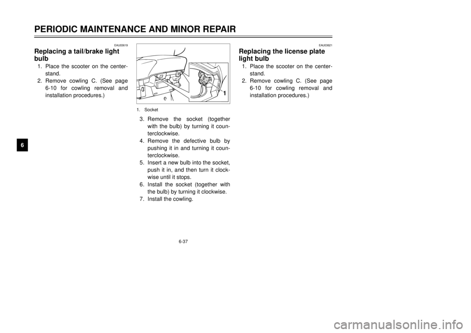
Replacing a tail/brake light
bulb1.Place the scooter on the center-
stand.
2.Remove cowling C. (See page
6-10 for cowling removal and
installation procedures.)
EAU03621
Replacing the license plate
light bulb1.Place the scooter on the center-
stand.
2.Remove cowling C. (See page
6-10 for cowling removal and
installation procedures.)
1
1.Socket3.Remove the socket (together
with the bulb) by turning it coun-
terclockwise.
4.Remove the defective bulb by
pushing it in and turning it coun-
terclockwise.
5.Insert a new bulb into the socket,
push it in, and then turn it clock-
wise until it stops.
6.Install the socket (together with
the bulb) by turning it clockwise.
7.Install the cowling.
5GM-9-E1(No ABS) 9/27/00 2:18 PM Page 80
Page 88 of 106

7-2
SCOOTER CARE AND STORAGE
1
2
3
4
5
67
8
9 8Do not use any harsh chemical
products on plastic parts. Be
sure to avoid using cloths or
sponges which have been in
contact with strong or abra-
sive cleaning products, sol-
vent or thinner, fuel (gasoline),
rust removers or inhibitors,
brake fluid, antifreeze or elec-
trolyte.
8Do not use high-pressure
washers or steam-jet cleaners
since they cause water seep-
age and deterioration in the
following areas: seals (of
wheel and swingarm bearings,
fork and brakes), electric com-
ponents (couplers, connec-
tors, instruments, switches
and lights), breather hoses
and vents.8For scooters equipped with a
windshield: Do not use strong
cleaners or hard sponges as
they will cause dulling or
scratching. Some cleaning
compounds for plastic may
leave scratches on the wind-
shield. Test the product on a
small hidden part of the wind-
shield to make sure that it
does not leave any marks. If
the windshield is scratched,
use a quality plastic polishing
compound after washing.
After normal useRemove dirt with warm water, a mild
detergent, and a soft, clean sponge,
and then rinse thoroughly with clean
water. Use a toothbrush or bottle-
brush for hard-to-reach areas.
Stubborn dirt and insects will come
off more easily if the area is covered
with a wet cloth for a few minutes
before cleaning.After riding in the rain, near the sea
or on salt-sprayed roadsSince sea salt or salt sprayed on the
roads during winter are extremely
corrosive in combination with water,
carry out the following steps after
each ride in the rain, near the sea or
on salt-sprayed roads.NOTE:
Salt sprayed on roads in the winter
may remain well into spring.1.Clean the scooter with cold water
and a mild detergent after the
engine has cooled down.
ECA00012
cCDo not use warm water since it
increases the corrosive action of
the salt.2.Apply a corrosion protection
spray on all metal, including
chrome- and nickel-plated, sur-
faces to prevent corrosion.
5GM-9-E1(No ABS) 9/27/00 2:18 PM Page 87