Page 236 of 256
Celica_U
2352000 CELICA (OM20735U)
2. Unplug the connector. Remove therubber cover.
If the connector is tight, wiggle it.3. Release the bulb retaining spring and remove the bulb along with the
socket. Install a new bulb into the
socket and return the bulb retaining
spring to its original position.
To install a bulb, align the tabs of the
bulb with the cutout of the mounting hole.4. Install the rubber cover with the “TOP” mark upward, and snuggle on
the boss. Insert the connector.
Make sure the rubber cover fits snugly on
the connector and the headlight body.
Aiming is not necessary after replacing
the bulb. When aiming adjustment is nec-
essary, contact your Toyota dealer.
ProCarManuals.com
Page 237 of 256
Celica_U
2362000 CELICA (OM20735U)
5. RIGHT SIDE HEADLIGHT: Install thecover.
NOTICE
Always notch the washer hose before
fastening it when installing the cover.
This prevents washer hose damage.
—Headlights (high beam)
1. Open the hood.
RIGHT SIDE HEADLIGHT: Remove the
clips and take out the cover. In doing
so, remove the washer hose from the
notch on the cover.
Remove and install the cover clips as
shown in the following illustrations.
ProCarManuals.com
Page 239 of 256
Celica_U
2382000 CELICA (OM20735U)
4. Insert the bulb base into the mount-ing hole by turning it clockwise.
Aiming is not necessary after replacing
the bulb. When aiming adjustment is nec-
essary, contact your Toyota dealer.5. RIGHT SIDE HEADLIGHT: Install the cover.
NOTICE
Always notch the washer hose before
fastening it when installing the cover.
This prevents washer hose damage.
If either the left or right front fog or
front side marker lights burns out, con-
tact your Toyota dealer.
NOTICE
Do not try to replace the front fog or
front side marker light bulbs by your-
self. You may damage the vehicle.
—Front fog and front side
marker lights
ProCarManuals.com
Page 240 of 256
Celica_U
2392000 CELICA (OM20735U)
—Parking lights
RIGHT SIDE PARKING LIGHT: Remove
and install the clips as shown in the
following illustrations.
NOTICE
Always notch the washer hose before
fastening it when installing the cover.
This prevents washer hose damage.
Removing clip
Installing clip
ProCarManuals.com
Page 241 of 256
Celica_U
2402000 CELICA (OM20735U)
—Front turn signal lights
RIGHT SIDE FRONT TURN SIGNAL
LIGHT: Remove and install the clips as
shown in the following illustrations.
NOTICE
Always notch the washer hose before
fastening it when installing the cover.
This prevents washer hose damage.
ProCarManuals.com
Page 242 of 256
Celica_U
2412000 CELICA (OM20735U)
Removing clip
Installing clip
Remove the cover.
—Rear turn signal, stop and
tail, and back−up lights
ProCarManuals.com
Page 243 of 256
Celica_U
2422000 CELICA (OM20735U)
a: Stop and tail light
b: Back−up light
c: Rear turn signal light
—License plate lights
Use a Phillips −head screwdriver.
Remove the cover.
ProCarManuals.com
Page 247 of 256

Celica_U
2462000 CELICA (OM20735U)
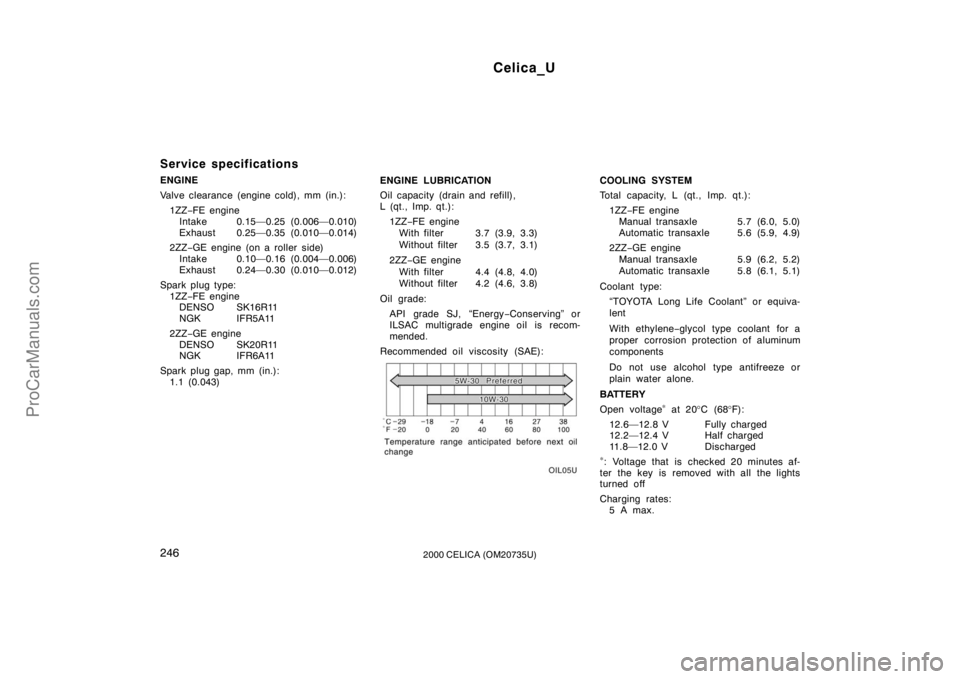
Service specifications
ENGINE
Valve clearance (engine cold), mm (in.):1ZZ −FE engine
Intake 0.15—0.25 (0.006—0.010)
Exhaust 0.25—0.35 (0.010—0.014)
2ZZ −GE engine (on a roller side)
Intake 0.10—0.16 (0.004—0.006)
Exhaust 0.24—0.30 (0.010—0.012)
Spark plug type: 1ZZ −FE engine
DENSO SK16R11
NGK IFR5A11
2ZZ −GE engine
DENSO SK20R11
NGK IFR6A11
Spark plug gap, mm (in.): 1.1 (0.043) ENGINE LUBRICATION
Oil capacity (drain and refill),
L (qt., Imp. qt.):
1ZZ −FE engine
With filter 3.7 (3.9, 3.3)
Without filter 3.5 (3.7, 3.1)
2ZZ −GE engine
With filter 4.4 (4.8, 4.0)
Without filter 4.2 (4.6, 3.8)
Oil grade: API grade SJ, “Energy −Conserving” or
ILSAC multigrade engine oil is recom-
mended.
Recommended oil viscosity (SAE):COOLING SYSTEM
Total capacity, L (qt., Imp. qt.): 1ZZ −FE engine
Manual transaxle 5.7 (6.0, 5.0)
Automatic transaxle 5.6 (5.9, 4.9)
2ZZ −GE engine
Manual transaxle 5.9 (6.2, 5.2)
Automatic transaxle 5.8 (6.1, 5.1)
Coolant type: “TOYOTA Long Life Coolant” or equiva-
lent
With ethylene− glycol type coolant for a
proper corrosion protection of aluminum
components
Do not use alcohol type antifreeze or
plain water alone.
BATTERY
Open voltage
∗ at 20 °C (68 °F):
12.6—12.8 V Fully charged
12.2—12.4 V Half charged
11.8—12.0 V Discharged
∗: Voltage that is checked 20 minutes af-
ter the key is removed with all the lights
turned off
Charging rates: 5 A max.
ProCarManuals.com