Page 116 of 447
7B-74 AUTOMATIC TRANSMISSION (4 A/T)
3) If selector lever is in “P” range, shift selector lever to other
than “P” range with releasing shift lock referring to “SHIFT
LOCK SOLENOID MANUAL RELEASE” in this section.
4) Install cable end (1) and cable casing cap (2) to key interlock
cam (3) and its bracket (4), then install cable (5) to selector
pad (6).
5) With selector lever set at “P” position, turn ignition key to
“ACC” position and then check for following conditions.
With knob button released, ignition key can be turned from
“ACC” position to “LOCK” position.
With knob button pressed, ignition key cannot be turned from
“ACC” position to “LOCK” position.
6) Install steering column referring to Section 3C.
7) Install steering column hole cover.
8) Install center console.
9) Connect negative cable at battery and enable air bag sys-
tem, referring to “ENABLING AIR BAG SYSTEM” in Section
10B (if equipped).
Page 122 of 447

7B-80 AUTOMATIC TRANSMISSION (4 A/T)
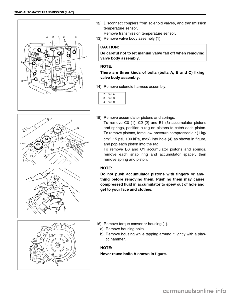
12) Disconnect couplers from solenoid valves, and transmission
temperature sensor.
Remove transmission temperature sensor.
13) Remove valve body assembly (1).
14) Remove solenoid harness assembly.
15) Remove accumulator pistons and springs.
To remove C0 (1), C2 (2) and B1 (3) accumulator pistons
and springs, position a rag on pistons to catch each piston.
To remove pistons, force low-pressure compressed air (1 kg/
cm
2, 15 psi, 100 kPa, max) into hole (4) as shown in figure,
and pop each piston into the rag.
To remove B0 and C1 accumulator pistons and springs,
remove each snap ring and accumulator spacer, then
remove spring and piston.
16) Remove torque converter housing (1).
a) Remove housing bolts.
b) Remove housing while tapping around it lightly with a plas-
tic hammer. CAUTION:
Be careful not to let manual valve fall off when removing
valve body assembly.
NOTE:
There are three kinds of bolts (bolts A, B and C) fixing
valve body assembly.
2. Bolt A
3. Bolt B
4. Bolt C
NOTE:
Do not push accumulator pistons with fingers or any-
thing before removing them. Pushing them may cause
compressed fluid in accumulator to spew out of hole and
get to your face and clothes.
NOTE:
Never reuse bolts A shown in figure.
Page 150 of 447
7B-108 AUTOMATIC TRANSMISSION (4 A/T)
Valve spring dimensions (Reference)
Lower Valve Body
1) Remove oil strainers (1).
2) Remove solenoid valves, if still attached.
3) Remove keys (2) and pull out all sleeve, plug, spring and
valves.
Valve spring dimensions (Reference)Spring Free length
“a” (mm)Outside diameter
“b” (mm)
Primary regula-
tor valve spring79.2 18.0
Lock-up control
valve spring31.1 8.5
Lock-up signal
valve spring36.1 8.5
3. Fail valve No.1 sleeve
4. Fail valve No.1
5. Cooler by-pass valve
6. Cooler by-pass valve spring
7. Manual valve
8. Secondary regulator valve
9. Secondary regulator valve spring
10. Secondary regulator valve plug
Spring Free length
“a” (mm)Outside diame-
ter “b” (mm)
Secondary regula-
tor valve spring38.7 8.8
Cooler by-pass
valve spring22.8 8.0
Page 173 of 447

AUTOMATIC TRANSMISSION (4 A/T) 7B-131
52) Install O-rings to each accumulator piston and apply grease
or ATF to them.
Grease 99000-25030
53) Install C1 and B0 accumulator pistons (1 and 6), springs (2,
3 and 7) and spacers (4).
Hold them with snap rings (5).
54) Install C0, B1, C2 accumulator springs (9, 12, 13, 15 and
16), spacer (11) and pistons (8, 10 and 14) as shown in fig-
ure.
55) Install wire-to-solenoid assembly (1).
Tightening torque
Wire - to - solenoid assembly bolt
(a) : 8 N·m (0.8 kg-m, 6.0 lb-ft)
Grease 99000-25030 NOTE:
C1 and B0 accumulator pistons are the same.
NOTE:
Make sure that snap rings are fitted to the groove of
each cylinder.
Make sure that O-rings are not twisted or caught when
installing.
NOTE:
Make sure that O-rings are not twisted or caught when
installing.
1. C1 accumulator piston 9. C0 accumulator spring
(with Pink paint)
2. C1 accumulator outer spring
(with Yellow paint)10. B1 accumulator piston
3. C1 accumulator inner spring
(with Yellow paint)11. B1 accumulator spacer
4. Spacer 12. B1 accumulator inner spring
(with Orange paint)
5. Snap ring 13. B1 accumulator outer spring
(with Orange paint)
6. B0 accumulator piston 14. C2 accumulator piston
7. B0 accumulator spring
(with Purple paint)15. C2 accumulator inner spring
(with Light Blue paint)
8. C0 accumulator piston 16. C2 accumulator outer spring
(with Light Blue paint)
NOTE:
Apply grease to O-ring of wire-to-solenoid assembly.
Page 174 of 447
7B-132 AUTOMATIC TRANSMISSION (4 A/T)
56) Install valve body assembly (1) to transmission case.
First match the pin of the manual valve to the slot of the
manual shift shaft.
To fix valve body assembly (1) to transmission case, first
tighten bolt B (3), then tighten other bolts.
Tightening torque
Valve body to transmission case bolts
: 10 N·m (1.0 kg-m, 7.5 lb-ft)
57) Connect couplers of wire-to-solenoid to solenoid valves.Bolt Length “a”Pieces
A 30 mm (1.20 in.) 7
B 31 mm (1.22 in.) 2
C 25 mm (0.98 in.) 2
2. Bolt A
4. Bolt C
5. Manual valve pin
6. Slot of manual shift shaft
Solenoid Valve Wire Color
A (No.1) White
B (No.2) Black
C (No.3) Red
D (No.4) Yellow
E (No.5) Brown
TCC (Lock-up) Orange
1. Solenoid valve No.1
2. Solenoid valve No.2
3. Solenoid valve No.3
4. Solenoid valve No.4
5. Solenoid valve No.5
6. Lock-up solenoid
Page 178 of 447

7B-136 AUTOMATIC TRANSMISSION (4 A/T)
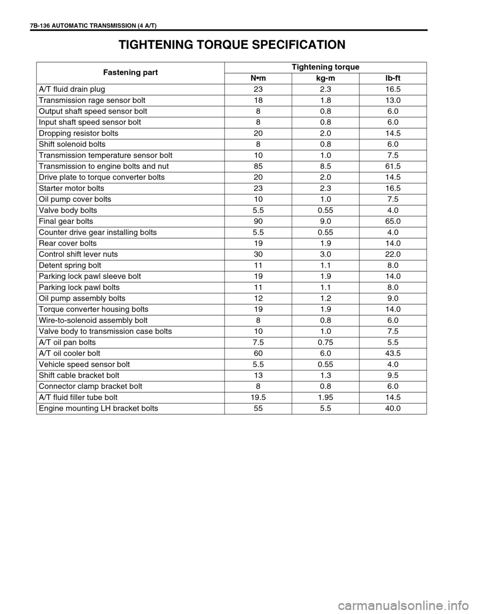
TIGHTENING TORQUE SPECIFICATION
Fastening partTightening torque
Nm kg-m lb-ft
A/T fluid drain plug 23 2.3 16.5
Transmission rage sensor bolt 18 1.8 13.0
Output shaft speed sensor bolt 8 0.8 6.0
Input shaft speed sensor bolt 8 0.8 6.0
Dropping resistor bolts 20 2.0 14.5
Shift solenoid bolts 8 0.8 6.0
Transmission temperature sensor bolt 10 1.0 7.5
Transmission to engine bolts and nut 85 8.5 61.5
Drive plate to torque converter bolts 20 2.0 14.5
Starter motor bolts 23 2.3 16.5
Oil pump cover bolts 10 1.0 7.5
Valve body bolts 5.5 0.55 4.0
Final gear bolts 90 9.0 65.0
Counter drive gear installing bolts 5.5 0.55 4.0
Rear cover bolts 19 1.9 14.0
Control shift lever nuts 30 3.0 22.0
Detent spring bolt 11 1.1 8.0
Parking lock pawl sleeve bolt 19 1.9 14.0
Parking lock pawl bolts 11 1.1 8.0
Oil pump assembly bolts 12 1.2 9.0
Torque converter housing bolts 19 1.9 14.0
Wire-to-solenoid assembly bolt 8 0.8 6.0
Valve body to transmission case bolts 10 1.0 7.5
A/T oil pan bolts 7.5 0.75 5.5
A/T oil cooler bolt 60 6.0 43.5
Vehicle speed sensor bolt 5.5 0.55 4.0
Shift cable bracket bolt 13 1.3 9.5
Connector clamp bracket bolt 8 0.8 6.0
A/T fluid filler tube bolt 19.5 1.95 14.5
Engine mounting LH bracket bolts 55 5.5 40.0