Page 99 of 447
AUTOMATIC TRANSMISSION (4 A/T) 7B-57
4) Lower vehicle and fill proper amount of an equivalent of
DEXRON
®-III or DEXRON®-IIE
5) Check fluid level according to procedure described under
“FLUID LEVEL AT NORMAL OPERATING TEMPERA-
TURE.
A/T fluid specification
: An equivalent of DEXRON
®-III or DEXRON®-IIE
A/T fluid capacity
When draining from drain plug hole :
4.0 liters (8.45/7.04 US/Imp. pt.)
When overhauling :
5.1 liters (10.78/8.98 US/Imp. pt.)
SELECTOR LEVER
1. Dipstick
2.“FULL HOT” mark
3.“LOW HOT” mark
4.“FULL COLD” mark
5.“LOW COLD” mark
1
1. Selector lever assembly 4. Selector indicator assembly
2. Selector lever knob assembly 5. Screw
3. Screw 6. Illumination lamp assembly
Page 104 of 447
7B-62 AUTOMATIC TRANSMISSION (4 A/T)
OUTPUT SHAFT SPEED SENSOR (A/T VSS)
INSPECTION
1) Disconnect negative cable at battery.
2) Disconnect output shaft speed sensor – input shaft speed
sensor coupler (1).
3) Check resistance between output shaft speed sensor termi-
nals (2).
Output shaft speed sensor resistance
Standard : 160 – 200
Ω
ΩΩ Ω at 20°C (68°F)
REMOVAL
1) Disconnect negative cable at battery.
2) Disconnect output shaft speed sensor – input shaft speed
sensor coupler.
3) Remove output shaft speed sensor (1) by removing its bolt.
INSTALLATION
1) Apply A/T fluid to output shaft speed sensor o-ring.
2) Install output shaft speed sensor (1) to A/T case and tighten
bolt to specified torque.
Tightening torque
Output shaft speed sensor bolt
(a) : 8 N·m (0.8 kg-m, 6.0 lb-ft)
3) Connect output shaft speed sensor – input shaft speed sen-
sor coupler.
4) Connect negative cable to battery.
Page 105 of 447

AUTOMATIC TRANSMISSION (4 A/T) 7B-63
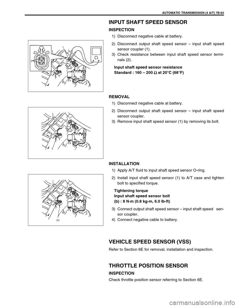
INPUT SHAFT SPEED SENSOR
INSPECTION
1) Disconnect negative cable at battery.
2) Disconnect output shaft speed sensor – input shaft speed
sensor coupler (1).
3) Check resistance between input shaft speed sensor termi-
nals (2).
Input shaft speed sensor resistance
Standard : 160 – 200
Ω
ΩΩ Ω at 20°C (68°F)
REMOVAL
1) Disconnect negative cable at battery.
2) Disconnect output shaft speed sensor – input shaft speed
sensor coupler.
3) Remove input shaft speed sensor (1) by removing its bolt.
INSTALLATION
1) Apply A/T fluid to input shaft speed sensor O-ring.
2) Install input shaft speed sensor (1) to A/T case and tighten
bolt to specified torque.
Tightening torque
Input shaft speed sensor bolt
(b) : 8 N·m (0.8 kg-m, 6.0 lb-ft)
3) Connect output shaft speed sensor – input shaft speed sen-
sor coupler.
4) Connect negative cable to battery.
VEHICLE SPEED SENSOR (VSS)
Refer to Section 6E for removal, installation and inspection.
THROTTLE POSITION SENSOR
INSPECTION
Check throttle position sensor referring to Section 6E.
Page 107 of 447
AUTOMATIC TRANSMISSION (4 A/T) 7B-65
O/D OFF SWITCH
INSPECTION
1) Remove console box.
2) Disconnect O/D off switch coupler (1).
3) Check continuity between O/D off switch terminals.
O/D OFF switch specification
SHIFT SOLENOID VALVES AND TRANSMIS-
SION TEMPERATURE SENSOR
REMOVAL
1) Disconnect negative cable at battery.
2) Drain A/T fluid.
3) Remove A/T oil pan (1).
4) Disconnect transmission temp. sensor coupler (3).
5) Remove A/T oil strainer (2) and transmission temp. sensor
(1). O/D off switch ON OFF
Continuity Continuity No continuity
2. O/D off switch ON
3. O/D off switch OFF
Page 109 of 447
AUTOMATIC TRANSMISSION (4 A/T) 7B-67
INSTALLATION
1) Install shift solenoid valves.
Tightening torque
Solenoid valve bolts (a) : 8 N·m (0.8 kg-m, 6.0 lb-ft)
2) Connect shift solenoid couplers.
3) Install oil strainer (2) and transmission temperature sensor
(1).
Tightening torque
Transmission temperature sensor bolt
(b) : 10 N·m (1.0 kg-m, 7.5 lb-ft)
4) Connect transmission temperature sensor coupler (3).
5) Clean mating surface of A/T oil pan (1) and A/T case.
6) Install new gasket (2) to A/T oil pan.
7) Install A/T oil pan.
Tightening torque
A/T oil pan bolts (a) : 7.5 N·m (0.75 kg-m, 5.5 lb-ft)
8) Install A/T fluid drain bolt.
Tightening torque
A/T fluid drain bolt (b) : 23 N·m (2.3 kg-m, 16.5 lb-ft)
9) Refill A/T fluid referring to “FLUID CHANGE” in this section.
10) Verify that there is no A/T fluid leakage.
NOTE:
Do not forget to install O-ring (4) to oil strainer first.
Page 110 of 447
7B-68 AUTOMATIC TRANSMISSION (4 A/T)
DIFFERENTIAL SIDE OIL SEAL
REPLACEMENT
1) Lift up vehicle and drain transmission oil.
2) Remove drive shaft joints from differential gear of transmis-
sion.
Refer to Section 4 for procedure to disconnect drive shaft
joints.
For differential side oil seal removal, it is not necessary to
remove drive shafts from steering knuckle.
For 4WD vehicle, remove transfer referring to Section 7D.
3) Remove differential side oil seal (1) by using flat end rod or
like.
4) Install new differential side oil seal by using special tool.
Special tool
(A) : 09940-53111
(B) : 09913-75510
5) Install drive shaft referring to Section 4.
6) Refill A/T fluid referring to “FLUID CHANGE” in this section. NOTE:
For oil seal installation, press-fit oil seal so that transmis-
sion case end face is flush with oil seal end face.
2. Steering gear box
3. A/T oil pan
4. Torque converter hous-
ing
5. Transmission case
Page 121 of 447
AUTOMATIC TRANSMISSION (4 A/T) 7B-79
4) Remove output shaft speed sensor (1) and input shaft speed
sensor (2).
5) Remove transmission range sensor (3).
6) Remove dropping resistor (4).
7) Remove breather hose (5).
8) Remove A/T fluid level gauge (1) and filler tube (2).
9) Remove vehicle speed sensor (1) (for speedometer), shift
cable bracket (2) and connector clamp bracket (3).
10) Remove oil pan and oil pan gasket.
11) Remove oil strainer assembly (1), and detach transmission
temperature sensor (2).
NOTE:
For removal of oil pan, do not turn transmission over
as this will contaminate valve body with foreign materi-
als in the bottom of oil pan.
When removing oil pan, tap around it lightly with a
plastic hammer. Do not force it off by using a screw-
driver or the like.
Page 122 of 447

7B-80 AUTOMATIC TRANSMISSION (4 A/T)
12) Disconnect couplers from solenoid valves, and transmission
temperature sensor.
Remove transmission temperature sensor.
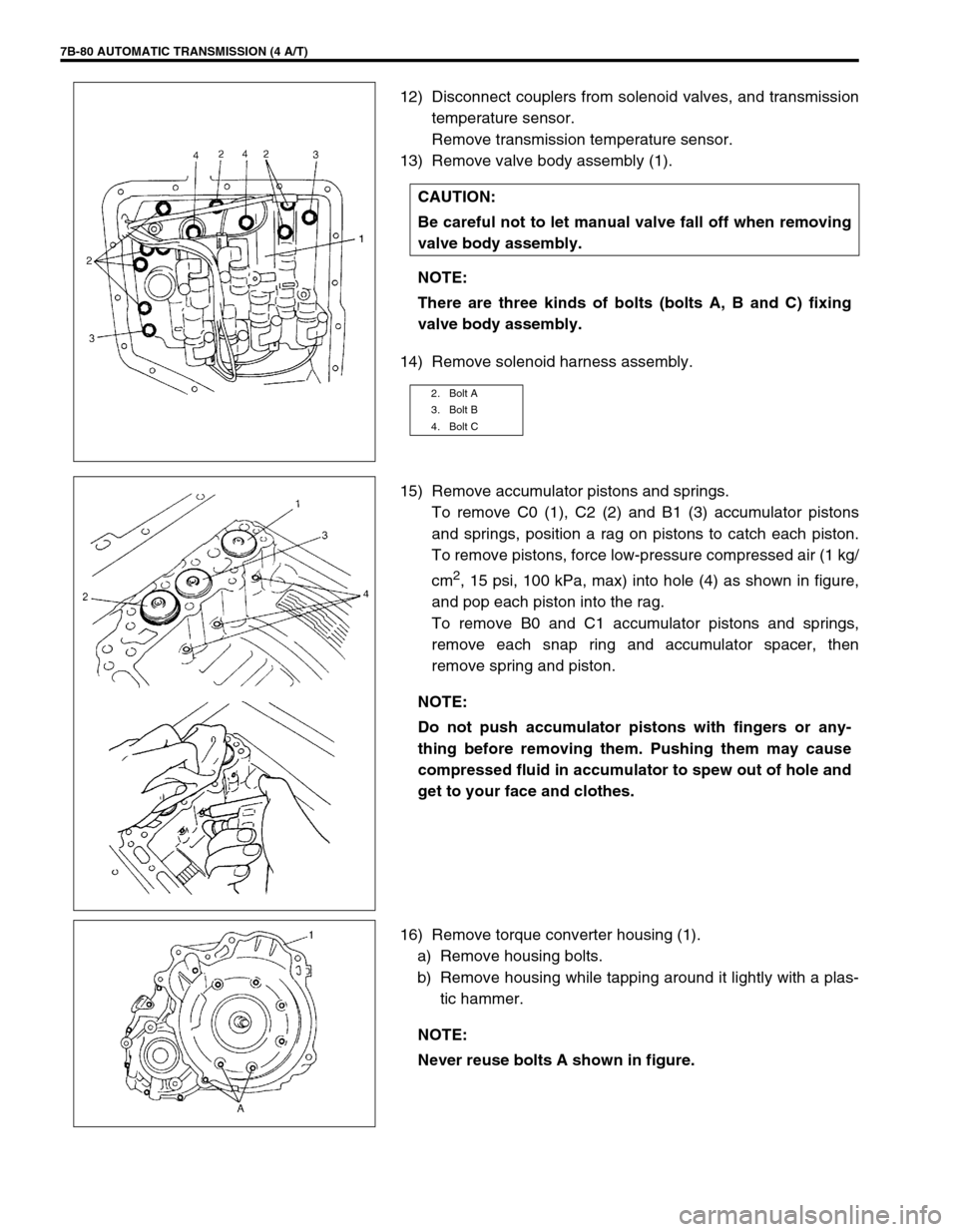
13) Remove valve body assembly (1).
14) Remove solenoid harness assembly.
15) Remove accumulator pistons and springs.
To remove C0 (1), C2 (2) and B1 (3) accumulator pistons
and springs, position a rag on pistons to catch each piston.
To remove pistons, force low-pressure compressed air (1 kg/
cm
2, 15 psi, 100 kPa, max) into hole (4) as shown in figure,
and pop each piston into the rag.
To remove B0 and C1 accumulator pistons and springs,
remove each snap ring and accumulator spacer, then
remove spring and piston.
16) Remove torque converter housing (1).
a) Remove housing bolts.
b) Remove housing while tapping around it lightly with a plas-
tic hammer. CAUTION:
Be careful not to let manual valve fall off when removing
valve body assembly.
NOTE:
There are three kinds of bolts (bolts A, B and C) fixing
valve body assembly.
2. Bolt A
3. Bolt B
4. Bolt C
NOTE:
Do not push accumulator pistons with fingers or any-
thing before removing them. Pushing them may cause
compressed fluid in accumulator to spew out of hole and
get to your face and clothes.
NOTE:
Never reuse bolts A shown in figure.