Page 390 of 557
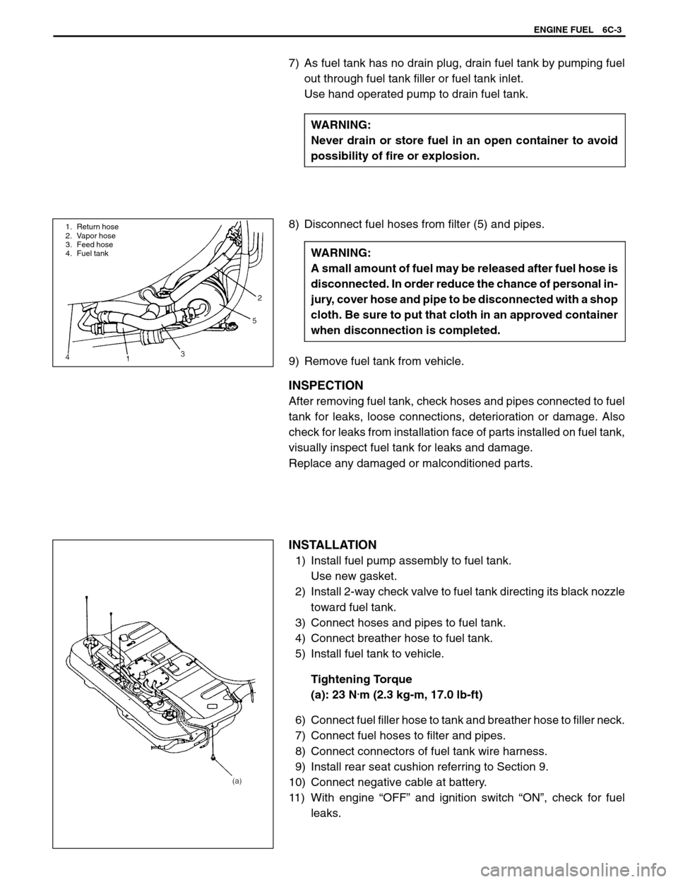
1. Return hose
2. Vapor hose
3. Feed hose
4. Fuel tank
ENGINE FUEL 6C-3
7) As fuel tank has no drain plug, drain fuel tank by pumping fuel
out through fuel tank filler or fuel tank inlet.
Use hand operated pump to drain fuel tank.
WARNING:
Never drain or store fuel in an open container to avoid
possibility of fire or explosion.
8) Disconnect fuel hoses from filter (5) and pipes.
WARNING:
A small amount of fuel may be released after fuel hose is
disconnected. In order reduce the chance of personal in-
jury, cover hose and pipe to be disconnected with a shop
cloth. Be sure to put that cloth in an approved container
when disconnection is completed.
9) Remove fuel tank from vehicle.
INSPECTION
After removing fuel tank, check hoses and pipes connected to fuel
tank for leaks, loose connections, deterioration or damage. Also
check for leaks from installation face of parts installed on fuel tank,
visually inspect fuel tank for leaks and damage.
Replace any damaged or malconditioned parts.
INSTALLATION
1) Install fuel pump assembly to fuel tank.
Use new gasket.
2) Install 2-way check valve to fuel tank directing its black nozzle
toward fuel tank.
3) Connect hoses and pipes to fuel tank.
4) Connect breather hose to fuel tank.
5) Install fuel tank to vehicle.
Tightening Torque
(a): 23 N
.m (2.3 kg-m, 17.0 lb-ft)
6) Connect fuel filler hose to tank and breather hose to filler neck.
7) Connect fuel hoses to filter and pipes.
8) Connect connectors of fuel tank wire harness.
9) Install rear seat cushion referring to Section 9.
10) Connect negative cable at battery.
11) With engine “OFF” and ignition switch “ON”, check for fuel
leaks.
Page 391 of 557
6C-4 ENGINE FUEL
FUEL PUMP ASSEMBLY
REMOVAL
1) Remove fuel tank (1) from vehicle referring to “FUEL TANK” in
this section.
2) Disconnect fuel feed hose (2), fuel return hose (3) and breather
hose (4) from fuel pump assembly (5).
3) Remove fuel pump assembly from fuel tank by removing
screws.
INSPECTION
Check fuel pump assembly for damage.
Check fuel suction filter (1) for evidence of dirt and contamination.
If present, replace or clean and check for presence of dirt in fuel
tank.
INSTALLATION
Reverse removal procedure for installation noting the followings.
�Use new gasket.
�Clamp hoses securely.
Page 394 of 557
ENGINE AND EMISSION CONTROL SYSTEM (TBI FOR G10) 6E1-3
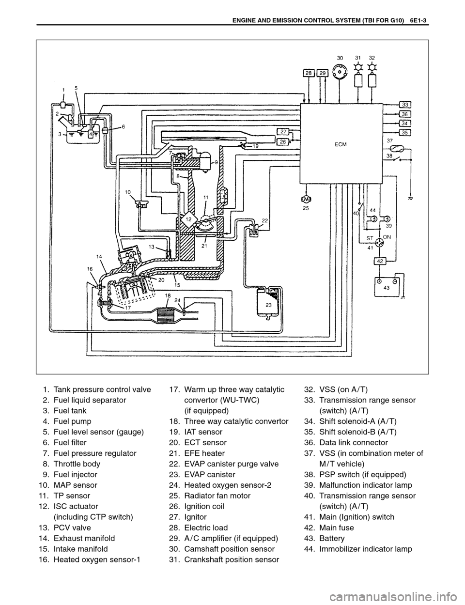
1. Tank pressure control valve
2. Fuel liquid separator
3. Fuel tank
4. Fuel pump
5. Fuel level sensor (gauge)
6. Fuel filter
7. Fuel pressure regulator
8. Throttle body
9. Fuel injector
10. MAP sensor
11. TP sensor
12. ISC actuator
(including CTP switch)
13. PCV valve
14. Exhaust manifold
15. Intake manifold
16. Heated oxygen sensor-117. Warm up three way catalytic
convertor (WU-TWC)
(if equipped)
18. Three way catalytic convertor
19. IAT sensor
20. ECT sensor
21. EFE heater
22. EVAP canister purge valve
23. EVAP canister
24. Heated oxygen sensor-2
25. Radiator fan motor
26. Ignition coil
27. Ignitor
28. Electric load
29. A / C amplifier (if equipped)
30. Camshaft position sensor
31. Crankshaft position sensor32. VSS (on A / T)
33. Transmission range sensor
(switch) (A / T)
34. Shift solenoid-A (A / T)
35. Shift solenoid-B (A / T)
36. Data link connector
37. VSS (in combination meter of
M / T vehicle)
38. PSP switch (if equipped)
39. Malfunction indicator lamp
40. Transmission range sensor
(switch) (A / T)
41. Main (Ignition) switch
42. Main fuse
43. Battery
44. Immobilizer indicator lamp
Page 395 of 557

1. Air cleaner
2. Throttle body
3. Fuel injector
4. Fuel pressure regulator
5. Intake manifold
6. Fuel filter
7. Fuel tank
8. Fuel pump
9. Fuel feed line
10. Fuel return line
11. Air
12. Fuel
13. Air/fuel mixture
6E1-4 ENGINE AND EMISSION CONTROL SYSTEM (TBI FOR G10)
The main components of this system are fuel tank,
fuel pump, fuel filter, throttle body (including fuel injec-
tor, fuel pressure regulator and idle speed control ac-
tuator), fuel feed line, fuel return line and air cleaner.
The fuel in the fuel tank is pumped up by the fuel
pump, filtered by the fuel filter and fed under pressure
to injector installed in throttle body. As the fuel pres-
sure applied to the fuel injector (the fuel pressure in
the fuel feed line) is always kept a certain amount
higher than the pressure in the intake manifold by the
fuel pressure regulator, the fuel is injected into the
throttle body in conic dispersion when the injectoropens according to the injection signal from ECM.
The fuel relieved by the fuel pressure regulator re-
turns through the fuel return line to the fuel tank.
The injected fuel is mixed with the air which has been
filtered through the air cleaner in the throttle body. The
air/fuel mixture is drawn through clearance between
throttle valve and bore.
Then the intake manifold distributes the air/fuel mix-
ture to each combustion chamber.
For the structure and operation of the fuel tank and fil-
ter, refer to SECTION 6C “ENGINE FUEL”.
AIR AND FUEL DELIVERY SYSTEM
Page 402 of 557

ENGINE AND EMISSION CONTROL SYSTEM (TBI FOR G10) 6E1-11
1. Fuel filler
2. Ignition switch3. Fuel return hose
4. Fuel feed hose
1. Fuel pump 2. Filter 3. Fuel tank
FUEL PUMP
ON-VEHICLE INSPECTION
WARNING:
When fuel filler cap is removed in any procedure, work must be
done with no smoking, in a well-ventilated area and away from
any open flames.
1) Remove filler cap and turn ON ignition switch.
Then fuel pump operating sound should be heard from fuel filler
for about 2 seconds and stop. Be sure to reinstall fuel filler cap
after checking.
If above check result is not satisfactory, advance to “DIAGNOS-
TIC FLOW TABLE B-2”.
2) Fuel pressure should be felt at fuel return hose for 2 seconds af-
ter ignition switch ON.
If fuel pressure is not felt, advance to “DIAGNOSTIC FLOW
TABLE B-3”.
REMOVAL
1) Remove fuel tank from body according to procedure described
in Section 6C and remove fuel pump from fuel tank.
2) Remove fuel pump from its bracket.
INSPECTION
Check fuel pump filter for evidence of dirt and contamination. If
present, clean and check for presence of dirt in fuel tank.
INSTALLATION
1) Install fuel pump to its bracket.
2) Install fuel pump to fuel tank and then install fuel tank to body ac-
cording to procedure described in Section 6C.
Page 407 of 557
6E1-16 ENGINE AND EMISSION CONTROL SYSTEM (TBI FOR G10)
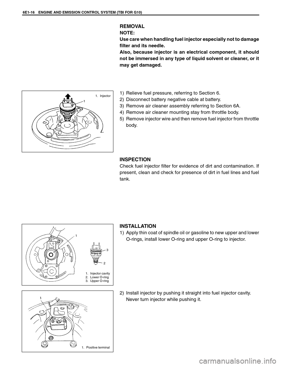
1. Injector
1
3
2
1. Injector cavity
2. Lower O-ring
3. Upper O-ring
1. Positive terminal
REMOVAL
NOTE:
Use care when handling fuel injector especially not to damage
filter and its needle.
Also, because injector is an electrical component, it should
not be immersed in any type of liquid solvent or cleaner, or it
may get damaged.
1) Relieve fuel pressure, referring to Section 6.
2) Disconnect battery negative cable at battery.
3) Remove air cleaner assembly referring to Section 6A.
4) Remove air cleaner mounting stay from throttle body.
5) Remove injector wire and then remove fuel injector from throttle
body.
INSPECTION
Check fuel injector filter for evidence of dirt and contamination. If
present, clean and check for presence of dirt in fuel lines and fuel
tank.
INSTALLATION
1) Apply thin coat of spindle oil or gasoline to new upper and lower
O-rings, install lower O-ring and upper O-ring to injector.
2) Install injector by pushing it straight into fuel injector cavity.
Never turn injector while pushing it.
Page 435 of 557
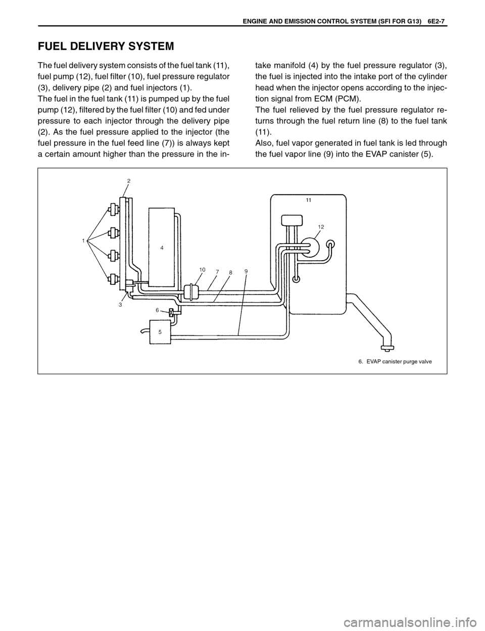
6. EVAP canister purge valve
ENGINE AND EMISSION CONTROL SYSTEM (SFI FOR G13) 6E2-7
The fuel delivery system consists of the fuel tank (11),
fuel pump (12), fuel filter (10), fuel pressure regulator
(3), delivery pipe (2) and fuel injectors (1).
The fuel in the fuel tank (11) is pumped up by the fuel
pump (12), filtered by the fuel filter (10) and fed under
pressure to each injector through the delivery pipe
(2). As the fuel pressure applied to the injector (the
fuel pressure in the fuel feed line (7)) is always kept
a certain amount higher than the pressure in the in-take manifold (4) by the fuel pressure regulator (3),
the fuel is injected into the intake port of the cylinder
head when the injector opens according to the injec-
tion signal from ECM (PCM).
The fuel relieved by the fuel pressure regulator re-
turns through the fuel return line (8) to the fuel tank
(11).
Also, fuel vapor generated in fuel tank is led through
the fuel vapor line (9) into the EVAP canister (5).
FUEL DELIVERY SYSTEM
Page 449 of 557
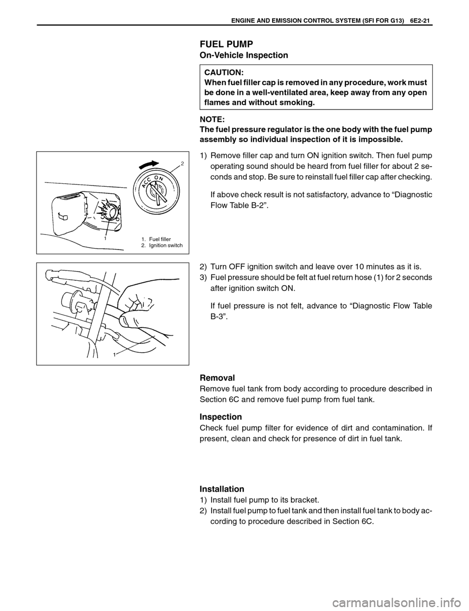
1. Fuel filler
2. Ignition switch
ENGINE AND EMISSION CONTROL SYSTEM (SFI FOR G13) 6E2-21
FUEL PUMP
On-Vehicle Inspection
CAUTION:
When fuel filler cap is removed in any procedure, work must
be done in a well-ventilated area, keep away from any open
flames and without smoking.
NOTE:
The fuel pressure regulator is the one body with the fuel pump
assembly so individual inspection of it is impossible.
1) Remove filler cap and turn ON ignition switch. Then fuel pump
operating sound should be heard from fuel filler for about 2 se-
conds and stop. Be sure to reinstall fuel filler cap after checking.
If above check result is not satisfactory, advance to “Diagnostic
Flow Table B-2”.
2) Turn OFF ignition switch and leave over 10 minutes as it is.
3) Fuel pressure should be felt at fuel return hose (1) for 2 seconds
after ignition switch ON.
If fuel pressure is not felt, advance to “Diagnostic Flow Table
B-3”.
Removal
Remove fuel tank from body according to procedure described in
Section 6C and remove fuel pump from fuel tank.
Inspection
Check fuel pump filter for evidence of dirt and contamination. If
present, clean and check for presence of dirt in fuel tank.
Installation
1) Install fuel pump to its bracket.
2) Install fuel pump to fuel tank and then install fuel tank to body ac-
cording to procedure described in Section 6C.
Page:
< prev 1-8 9-16 17-24