Page 201 of 698
3D-8 FRONT SUSPENSION
Tighten strut nut to specified torque by using special tools.
Tightening torque
Strut nut (a) : 50 N·m (5.0 kg-m, 36.5 lb-ft)
Special tool
(A) : 09900-00411
(B) : 09900-00414
(C) : 09945-26010
INSTALLATION
Install strut assembly by reversing removal procedure, noting the
following instructions.
Insert bolts in such direction as shown in figure.
Tighten all fasteners to specified torque.
Tightening torque
Strut bracket nut (a) : 105 N·m (10.5 kg-m, 76.0 lb-ft)
Strut support nut (b) : 23 N·m (2.3 kg-m, 17.0 lb-ft)
Tighten wheel nut to specified torque.
Tightening torque
Wheel nut : 85 N·m (8.5 kg-m, 61.5 lb-ft)
After installation, confirm front end (wheel) alignment refer-
ring to Section 3A.
NOTE:
Don’t twist brake hose when installing it.
Install E-ring (1) as far as it fits to bracket (2) as shown
in figure.
Page 211 of 698
3D-18 FRONT SUSPENSION
2) Press-fit bushing so that dimensions “A” and “B” in figure
become equal.
INSTALLATION
1) Install body side of suspension control arm but tighten sus-
pension control arm bolt (1) only temporarily.
2) Install suspension control arm ball joint to steering knuckle.
Align ball stud groove with steering knuckle bolt hole. Then
install ball joint bolt (1) from the direction as shown in figure.
Tighten suspension arm ball joint bolt (1) to specified torque.
Tightening torque
Suspension arm ball joint bolt
(a) : 60 N·m (6.0 kg-m, 43.5 lb-ft)
3) Install stabilizer bar, referring to “STABILIZER BAR AND/OR
BUSHINGS” in this section.
4) Lower hoist and vehicle in non-loaded condition, tighten con-
trol arm bolt (1) to specified torque.
Tightening torque
Control arm bolt (a) : 60 N·m (6.0 kg-m, 43.5 lb-ft)
5) Confirm front end (wheel) alignment referring to Section 3A.
F: Forward
Page 277 of 698

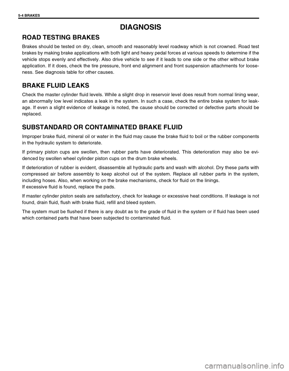
5-4 BRAKES
DIAGNOSIS
ROAD TESTING BRAKES
Brakes should be tested on dry, clean, smooth and reasonably level roadway which is not crowned. Road test
brakes by making brake applications with both light and heavy pedal forces at various speeds to determine if the
vehicle stops evenly and effectively. Also drive vehicle to see if it leads to one side or the other without brake
application. If it does, check the tire pressure, front end alignment and front suspension attachments for loose-
ness. See diagnosis table for other causes.
BRAKE FLUID LEAKS
Check the master cylinder fluid levels. While a slight drop in reservoir level does result from normal lining wear,
an abnormally low level indicates a leak in the system. In such a case, check the entire brake system for leak-
age. If even a slight evidence of leakage is noted, the cause should be corrected or defective parts should be
replaced.
SUBSTANDARD OR CONTAMINATED BRAKE FLUID
Improper brake fluid, mineral oil or water in the fluid may cause the brake fluid to boil or the rubber components
in the hydraulic system to deteriorate.
If primary piston cups are swollen, then rubber parts have deteriorated. This deterioration may also be evi-
denced by swollen wheel cylinder piston cups on the drum brake wheels.
If deterioration of rubber is evident, disassemble all hydraulic parts and wash with alcohol. Dry these parts with
compressed air before assembly to keep alcohol out of the system. Replace all rubber parts in the system,
including hoses. Also, when working on the brake mechanisms, check for fluid on the linings.
If excessive fluid is found, replace the pads.
If master cylinder piston seals are satisfactory, check for leakage or excessive heat conditions. If leakage is not
found, drain fluid, flush with brake fluid, refill and bleed system.
The system must be flushed if there is any doubt as to the grade of fluid in the system or if fluid has been used
which contained parts that have been subjected to contaminated fluid.
Page 278 of 698

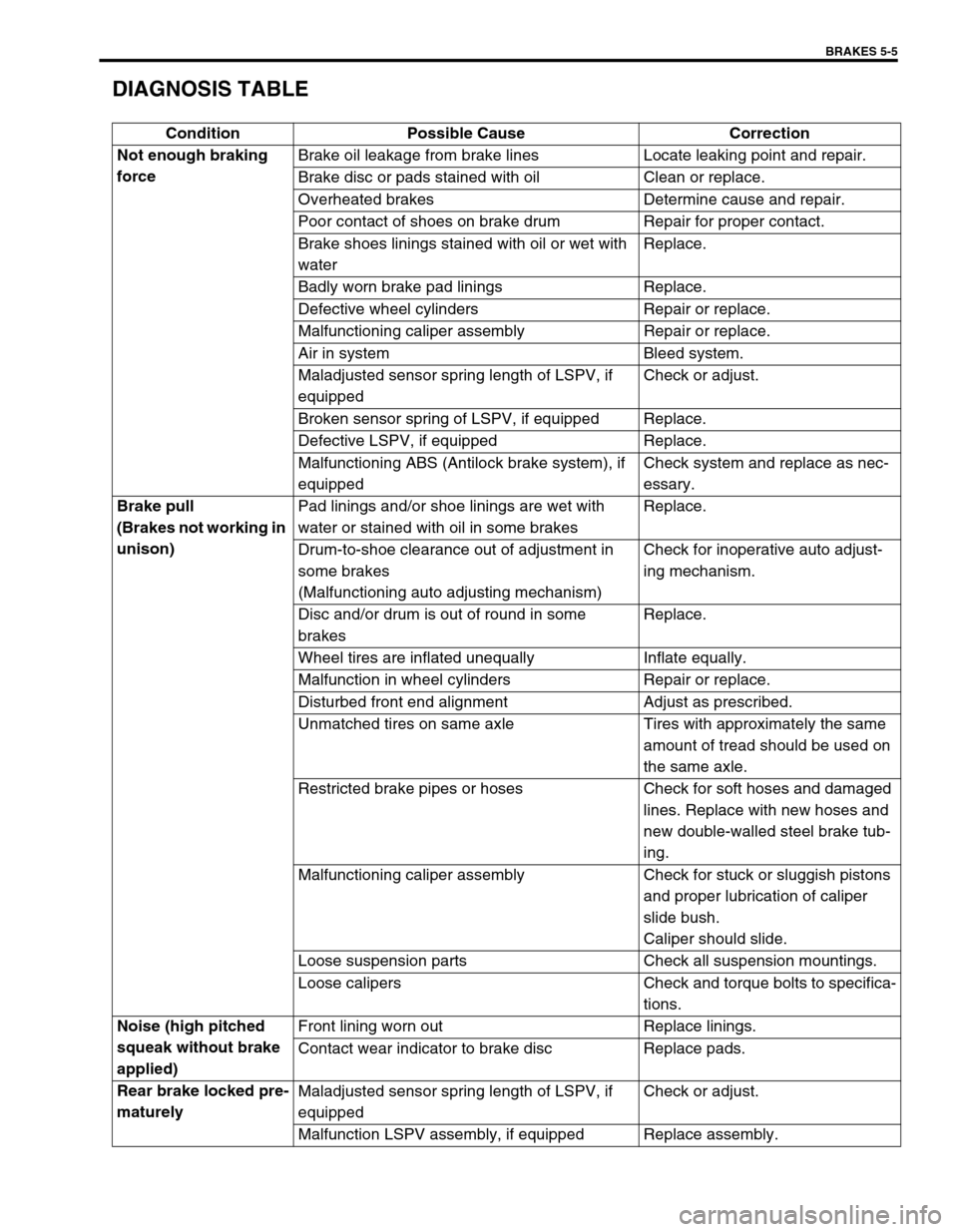
BRAKES 5-5
DIAGNOSIS TABLE
Condition Possible Cause Correction
Not enough braking
forceBrake oil leakage from brake lines Locate leaking point and repair.
Brake disc or pads stained with oil Clean or replace.
Overheated brakes Determine cause and repair.
Poor contact of shoes on brake drum Repair for proper contact.
Brake shoes linings stained with oil or wet with
waterReplace.
Badly worn brake pad linings Replace.
Defective wheel cylinders Repair or replace.
Malfunctioning caliper assembly Repair or replace.
Air in system Bleed system.
Maladjusted sensor spring length of LSPV, if
equippedCheck or adjust.
Broken sensor spring of LSPV, if equipped Replace.
Defective LSPV, if equipped Replace.
Malfunctioning ABS (Antilock brake system), if
equippedCheck system and replace as nec-
essary.
Brake pull
(Brakes not working in
unison)Pad linings and/or shoe linings are wet with
water or stained with oil in some brakesReplace.
Drum-to-shoe clearance out of adjustment in
some brakes
(Malfunctioning auto adjusting mechanism)Check for inoperative auto adjust-
ing mechanism.
Disc and/or drum is out of round in some
brakesReplace.
Wheel tires are inflated unequally Inflate equally.
Malfunction in wheel cylinders Repair or replace.
Disturbed front end alignment Adjust as prescribed.
Unmatched tires on same axle Tires with approximately the same
amount of tread should be used on
the same axle.
Restricted brake pipes or hoses Check for soft hoses and damaged
lines. Replace with new hoses and
new double-walled steel brake tub-
ing.
Malfunctioning caliper assembly Check for stuck or sluggish pistons
and proper lubrication of caliper
slide bush.
Caliper should slide.
Loose suspension parts Check all suspension mountings.
Loose calipers Check and torque bolts to specifica-
tions.
Noise (high pitched
squeak without brake
applied)Front lining worn out Replace linings.
Contact wear indicator to brake disc Replace pads.
Rear brake locked pre-
maturelyMaladjusted sensor spring length of LSPV, if
equippedCheck or adjust.
Malfunction LSPV assembly, if equipped Replace assembly.
Page:
< prev 1-8 9-16 17-24