2000 SUZUKI SWIFT wheel torque
[x] Cancel search: wheel torquePage 130 of 698

MANUAL RACK AND PINION 3B-9
INSTALLATION
1) Mount steering gear case (2) to body and tighten gear case
mount bolts (1) to specified torque.
Tightening torque
Gear case mount bolt (a) : 25 N·m (2.5 kg-m, 18.0 lb-ft)
2) Install exhaust No.1 pipe (3).
3) Install both tie rod ends (1) to knuckles (2). Tighten each
castle nut (3) until holes for split pin (4) align but within spec-
ified torque and then bend new split pin as shown.
Tightening torque
Castle nut (b) : 43 N·m (4.3 kg-m, 31.5 lb-ft)
4) Be sure that steering wheel and both brake discs are all
straight ahead driving state and then insert steering lower
joint into steering pinion shaft.
5) Tighten steering shaft joint bolts to specified torque (Lower
side (2) first and then upper side (1)).
Tightening torque
Steering shaft joint bolt (c) : 25 N·m (2.5 kg-m, 18.0 lb-ft)2
1, (a)
1
Page 131 of 698

3B-10 MANUAL RACK AND PINION
6) Reinstall cover (1) removed previously to steering shaft joint.
7) Put back floor mat as it was.
8) Install both wheels and tighten wheel nuts to specified
torque.
Tightening torque
Wheel nut : 85 N·m (8.5 kg-m, 61.5 lb-ft)
9) Lower hoist.
10) Check toe setting. Adjust as required (refer to Section 3A).
11) Tighten both tie rod end lock nuts to specified torque.
Tightening torque
Tie rod end lock nut (d) : 45 N·m (4.5 kg-m, 32.5 lb-ft)
RACK BOOT/TIE ROD
REMOVAL
1) Remove steering gear case by performing “MANUAL RACK
AND PINION ASSEMBLY REMOVAL” of this section.
2) For ease of adjustment after installation, make marking (1) of
tie rod end lock nut position of tie rod end thread.
3) Loosen tie rod end lock nut and remove tie rod end.
4) Remove boot wire (2) and clip (1).
5) Remove boot from tie rod.
Page 142 of 698
ELECTRICAL POWER STEERING (P/S) SYSTEM 3B1-1
6F1
6F2
6G
6H
6K
7A
7A1
3B1
7D
7E
7F
8A
8B
8C
8D
8E
9
10
10A
10B
SECTION 3B1
ELECTRICAL POWER STEERING (P/S) SYSTEM
CONTENTS
GENERAL DESCRIPTION .............................3B1-2
SYSTEM COMPONENTS ........................... 3B1-2
WIRING DIAGRAM ..................................... 3B1-3
DIAGNOSIS ....................................................3B1-4
ON-BOARD DIAGNOSTIC SYSTEM .......... 3B1-4
PRECAUTIONS IN DIAGNOSING
TROUBLES ................................................. 3B1-4
SYSTEM CHECK FLOW TABLE ................ 3B1-5
MALFUNCTION INDICATOR LAMP
(“EPS” WARNING LAMP) CHECK.............. 3B1-7
DTC CHECK ............................................... 3B1-8
DTC CLEARANCE ...................................... 3B1-9
SERIAL DATA LINK CIRCUIT CHECK ..... 3B1-10
DTC TABLE .............................................. 3B1-11
TABLE A - MALFUNCTION INDICATOR
LAMP DOES NOT COME ON AT
IGNITION SWITCH ON BUT LEAVING
ENGINE OFF ............................................ 3B1-13
TABLE B - MALFUNCTION INDICATOR
LAMP FLASHES AT IGNITION SWITCH
ON ............................................................. 3B1-15
TABLE C - MALFUNCTION INDICATOR
LAMP DOES NOT FLASH, JUST
REMAINS ON OR JUST REMAINS OFF
EVEN WITH DIAGNOSIS SWITCH
TERMINAL GROUNDED .......................... 3B1-15
DTC C1111 (DTC No.11) TORQUE
SENSOR MAIN CIRCUIT FAILURE ......... 3B1-16
DTC C1113 (DTC No.13) TORQUE
SENSOR MAIN AND SUB CIRCUIT
FAILURE ................................................... 3B1-16DTC C1115 (DTC No.15) TORQUE
SENSOR SUB CIRCUIT FAILURE........... 3B1-16
DTC C1114 (DTC No.14) TORQUE
SENSOR 5V POWER SUPPLY CIRCUIT
FAILURE ................................................... 3B1-17
DTC C1116 (DTC No.16) TORQUE
SENSOR 8V POWER SUPPLY CIRCUIT
FAILURE ................................................... 3B1-18
DTC C1121/C1123/C1124
(DTC No.21/23/24) VSS CIRCUIT
FAILURE ................................................... 3B1-19
DTC C1122 (DTC No.22) ENGINE
SPEED SIGNAL CIRCUIT FAILURE ........ 3B1-20
DTC C1141/C1142/C1143/C1144/C1145
(DTC No.41/42/43/44/45) MOTOR
CIRCUIT FAILURE ................................... 3B1-21
DTC C1151 (DTC No.51) CLUTCH
CIRCUIT FAILURE ................................... 3B1-22
DTC C1153(DTC No.53) P/S CONTROL
MODULE POWER SUPPLY CIRCUIT
FAILURE ................................................... 3B1-24
DTC C1152/C1154/C1155
(DTC No.52/54/55) P/S CONTROL
MODULE FAILURE .................................. 3B1-24
TROUBLE DIAGNOSIS (FOR TROUBLE
NOT INDICATED BY ON BOARD
DIAGNOSTIC SYSTEM)........................... 3B1-25
INSPECTION OF P/S CONTROL
MODULE AND ITS CIRCUITS ................. 3B1-26
STEERING WHEEL PLAY
INSPECTION ............................................ 3B1-28 WARNING:
For vehicles equipped with Supplemental Restraint (Air Bag) System :
Service on and around the air bag system components or wiring must be performed only by an
authorized SUZUKI dealer. Refer to “Air Bag System Components and Wiring Location View” under
“General Description” in air bag system section in order to confirm whether you are performing ser-
vice on or near the air bag system components or wiring. Please observe all WARNINGS and “Ser-
vice Precautions” under “On-Vehicle Service” in air bag system section before performing service
on or around the air bag system components or wiring. Failure to follow WARNINGS could result in
unintentional activation of the system or could render the system inoperative. Either of these two
conditions may result in severe injury.
Technical service work must be started at least 90 seconds after the ignition switch is turned to the
“LOCK” position and the negative cable is disconnected from the battery. Otherwise, the system
may be activated by reserve energy in the Sensing and Diagnostic Module (SDM).
Page 143 of 698
3B1-2 ELECTRICAL POWER STEERING (P/S) SYSTEM
STEERING FORCE INSPECTION ........... 3B1-28
ON-VEHICLE SERVICE ............................... 3B1-29
P/S CONTROL MODULE ......................... 3B1-29
TORQUE SENSOR .................................. 3B1-29MOTOR AND CLUTCH ............................ 3B1-30
STEERING COLUMN ASSEMBLY .......... 3B1-31
SPECIAL TOOL ........................................... 3B1-31
GENERAL DESCRIPTION
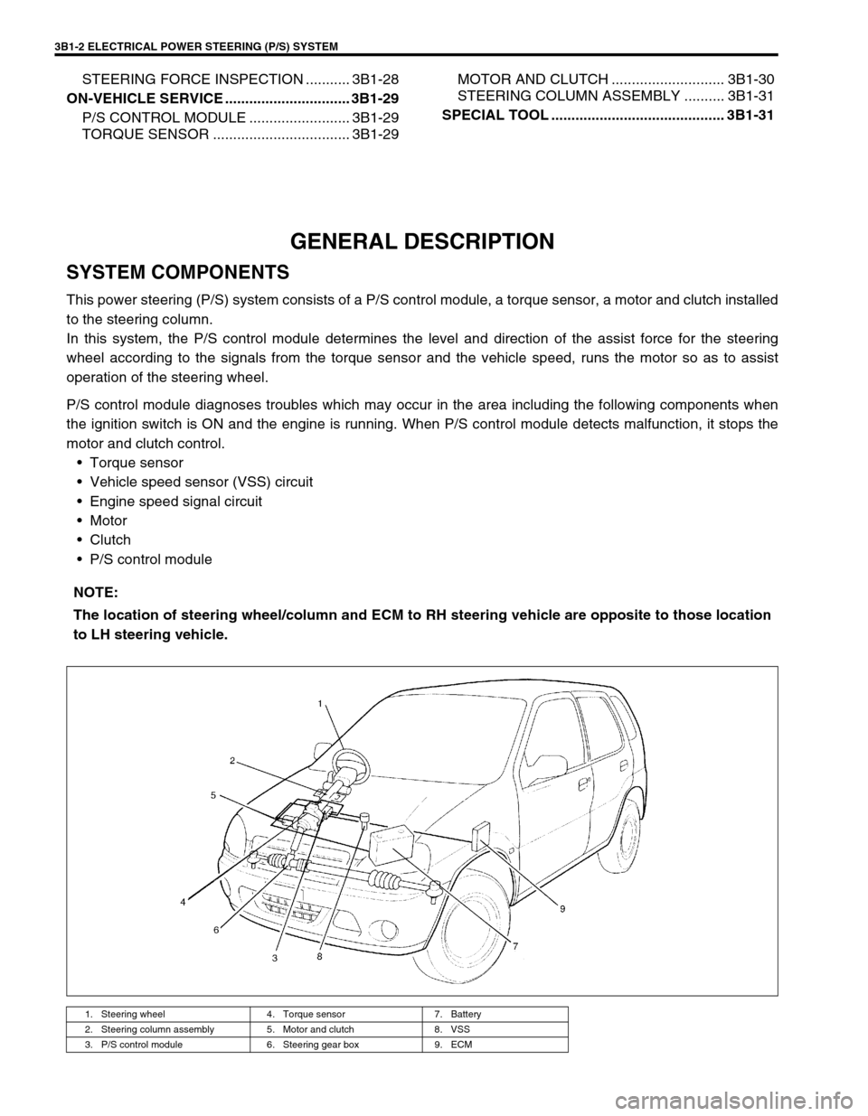
SYSTEM COMPONENTS
This power steering (P/S) system consists of a P/S control module, a torque sensor, a motor and clutch installed
to the steering column.
In this system, the P/S control module determines the level and direction of the assist force for the steering
wheel according to the signals from the torque sensor and the vehicle speed, runs the motor so as to assist
operation of the steering wheel.
P/S control module diagnoses troubles which may occur in the area including the following components when
the ignition switch is ON and the engine is running. When P/S control module detects malfunction, it stops the
motor and clutch control.
Torque sensor
Vehicle speed sensor (VSS) circuit
Engine speed signal circuit
Motor
Clutch
P/S control module
NOTE:
The location of steering wheel/column and ECM to RH steering vehicle are opposite to those location
to LH steering vehicle.
1. Steering wheel 4. Torque sensor 7. Battery
2. Steering column assembly 5. Motor and clutch 8. VSS
3. P/S control module 6. Steering gear box 9. ECM
Page 166 of 698

ELECTRICAL POWER STEERING (P/S) SYSTEM 3B1-25
TROUBLE DIAGNOSIS (FOR TROUBLE NOT INDICATED BY ON BOARD DIAG-
NOSTIC SYSTEM)
This section describes trouble diagnosis of P/S system parts whose trouble is not indicated by the on-board
diagnostic system (self-diagnostic function).
When DTC No.12 is indicated by the on-board diagnostic system (self-diagnosis function) and assuredly those
steering basic parts as described in “DIAGNOSIS TABLE” in Section 3 are all in good condition, check the fol-
lowing power steering system parts which may be a possible cause for each symptom of the steering.
Condition Possible Cause Correction
Steering wheel feels
heavy (Perform
STEERING FORCE
INSPECTION before
diagnosis.)Steering wheel installed improperly (twisted) Install steering wheel correctly.
Poor performance of torque sensor Check torque sensor. Refer to
“TORQUE SENSOR”.
Poor performance of motor and clutch Check motor and clutch. Refer to
“MOTOR AND CLUTCH”.
Faulty steering column Replace.
Poor performance of VSS Check VSS. Refer to Section 6E.
Vehicle pulls to one
side during straight
drivingPoor performance of torque sensor Check torque sensor. Refer to
“TORQUE SENSOR”.
Poor recovery from
turnsPoor performance of torque sensor Check torque sensor. Refer to
“TORQUE SENSOR”.
Faulty steering column Replace.
Page 168 of 698
ELECTRICAL POWER STEERING (P/S) SYSTEM 3B1-27
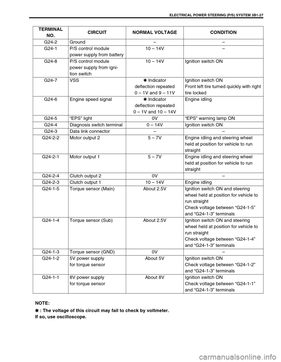
TERMINAL
NO.CIRCUIT NORMAL VOLTAGE CONDITION
G24-2 Ground––
G24-1 P/S control module
power supply from battery10 – 14V–
G24-8 P/S control module
power supply from igni-
tion switch10 – 14V Ignition switch ON
G24-7 VSS✱ Indicator
deflection repeated
0 – 1V and 9 – 11VIgnition switch ON
Front left tire turned quickly with right
tire locked
G24-6 Engine speed signal✱ Indicator
deflection repeated
0 – 1V and 10 – 14VEngine idling
G24-5“EPS” light 0V“EPS” warning lamp ON
G24-4 Diagnosis switch terminal 0 – 14V Ignition switch ON
G24-3 Data link connector––
G24-2-2 Motor output 2 5 – 7V Engine idling and steering wheel
held at position for vehicle to run
straight
G24-2-1 Motor output 1 5 – 7V Engine idling and steering wheel
held at position for vehicle to run
straight
G24-2-4 Clutch output 2 0V–
G24-2-3 Clutch output 1 10 – 14V Engine idling
G24-1-5 Torque sensor (Main) About 2.5V Ignition switch ON and steering
wheel held at position for vehicle to
run straight
Check voltage between “G24-1-5”
and “G24-1-3” terminals
G24-1-4 Torque sensor (Sub) About 2.5V Ignition switch ON and steering
wheel held at position for vehicle to
run straight
Check voltage between “G24-1-4”
and “G24-1-3” terminals
G24-1-3 Torque sensor (GND) 0V–
G24-1-2 5V power supply
for torque sensorAbout 5V Ignition switch ON
Check voltage between “G24-1-2”
and “G24-1-3” terminals
G24-1-1 8V power supply
for torque sensorAbout 8V Ignition switch ON
Check voltage between “G24-1-1”
and “G24-1-3” terminals
NOTE:
✱
✱✱ ✱ : The voltage of this circuit may fail to check by voltmeter.
If so, use oscilloscope.
Page 169 of 698
3B1-28 ELECTRICAL POWER STEERING (P/S) SYSTEM
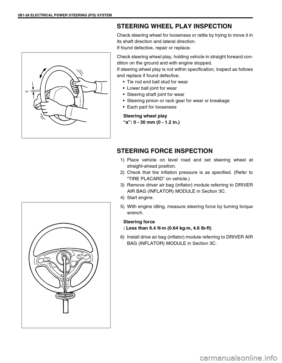
STEERING WHEEL PLAY INSPECTION
Check steering wheel for looseness or rattle by trying to move it in
its shaft direction and lateral direction.
If found defective, repair or replace.
Check steering wheel play, holding vehicle in straight forward con-
dition on the ground and with engine stopped.
If steering wheel play is not within specification, inspect as follows
and replace if found defective.
Tie rod end ball stud for wear
Lower ball joint for wear
Steering shaft joint for wear
Steering pinion or rack gear for wear or breakage
Each part for looseness
Steering wheel play
“a”: 0 - 30 mm (0 - 1.2 in.)
STEERING FORCE INSPECTION
1) Place vehicle on level road and set steering wheel at
straight-ahead position.
2) Check that tire inflation pressure is as specified. (Refer to
“TIRE PLACARD” on vehicle.)
3) Remove driver air bag (inflator) module referring to DRIVER
AIR BAG (INFLATOR) MODULE in Section 3C.
4) Start engine.
5) With engine idling, measure steering force by turning torque
wrench.
Steering force
: Less than 6.4 N·m (0.64 kg·m, 4.6 lb-ft)
6) Install drive air bag (inflator) module referring to DRIVER AIR
BAG (INFLATOR) MODULE in Section 3C.
Page 170 of 698
ELECTRICAL POWER STEERING (P/S) SYSTEM 3B1-29
ON-VEHICLE SERVICE
P/S CONTROL MODULE
REMOVAL
1) Disconnect negative cable at battery.
2) Remove steering column hole cover.
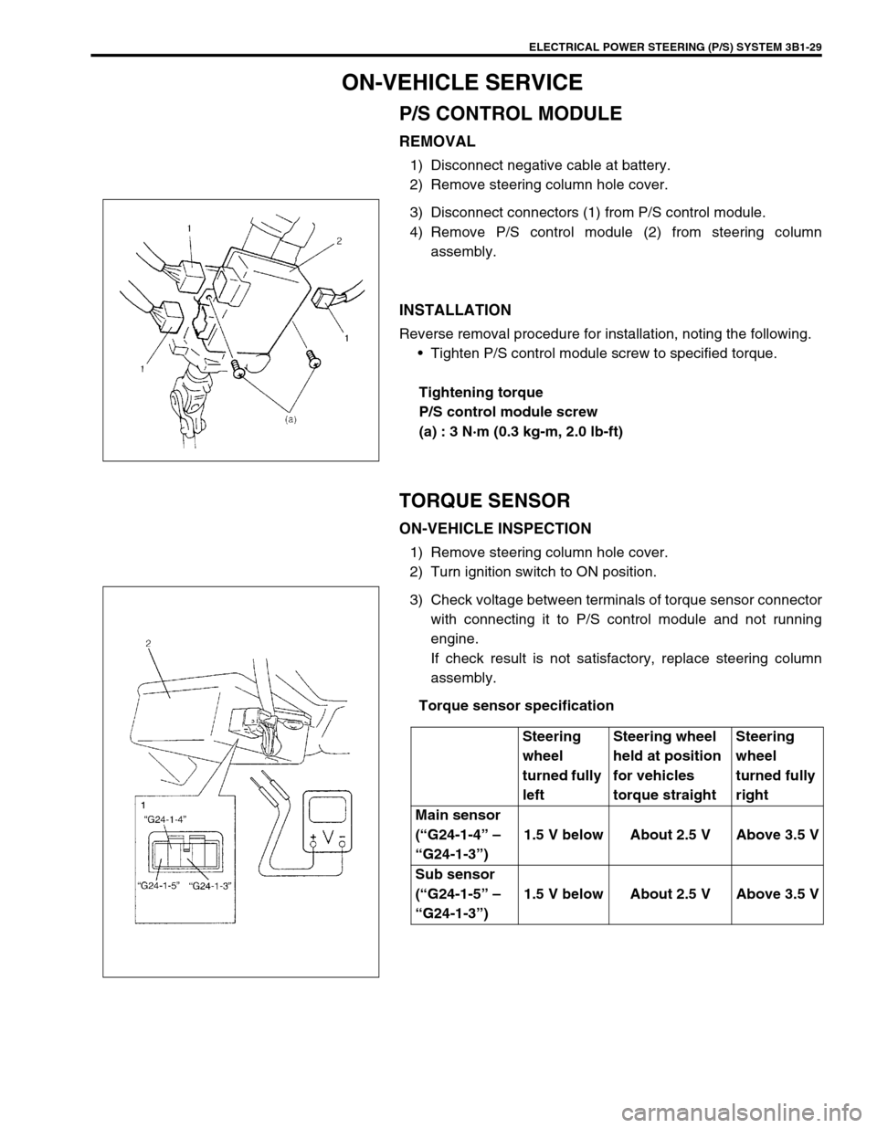
3) Disconnect connectors (1) from P/S control module.
4) Remove P/S control module (2) from steering column
assembly.
INSTALLATION
Reverse removal procedure for installation, noting the following.
Tighten P/S control module screw to specified torque.
Tightening torque
P/S control module screw
(a) : 3 N·m (0.3 kg-m, 2.0 lb-ft)
TORQUE SENSOR
ON-VEHICLE INSPECTION
1) Remove steering column hole cover.
2) Turn ignition switch to ON position.
3) Check voltage between terminals of torque sensor connector
with connecting it to P/S control module and not running
engine.
If check result is not satisfactory, replace steering column
assembly.
Torque sensor specification
Steering
wheel
turned fully
leftSteering wheel
held at position
for vehicles
torque straightSteering
wheel
turned fully
right
Main sensor
(“G24-1-4” –
“G24-1-3”)1.5 V below About 2.5 V Above 3.5 V
Sub sensor
(“G24-1-5” –
“G24-1-3”)1.5 V below About 2.5 V Above 3.5 V