Page 570 of 698
ENGINE MECHANICAL (M13 ENGINE) 6A1-69
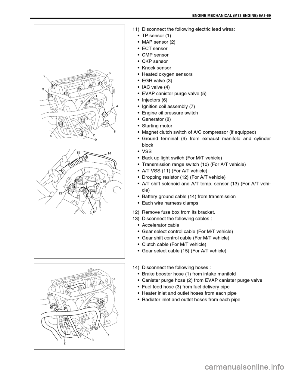
11) Disconnect the following electric lead wires:
TP sensor (1)
MAP sensor (2)
ECT sensor
CMP sensor
CKP sensor
Knock sensor
Heated oxygen sensors
EGR valve (3)
IAC valve (4)
EVAP canister purge valve (5)
Injectors (6)
Ignition coil assembly (7)
Engine oil pressure switch
Generator (8)
Starting motor
Magnet clutch switch of A/C compressor (if equipped)
Ground terminal (9) from exhaust manifold and cylinder
block
VSS
Back up light switch (For M/T vehicle)
Transmission range switch (10) (For A/T vehicle)
A/T VSS (11) (For A/T vehicle)
Dropping resistor (12) (For A/T vehicle)
A/T shift solenoid and A/T temp. sensor (13) (For A/T vehi-
cle)
Battery ground cable (14) from transmission
Each wire harness clamps
12) Remove fuse box from its bracket.
13) Disconnect the following cables :
Accelerator cable
Gear select control cable (For M/T vehicle)
Gear shift control cable (For M/T vehicle)
Clutch cable (For M/T vehicle)
Gear select cable (15) (For A/T vehicle)
14) Disconnect the following hoses :
Brake booster hose (1) from intake manifold
Canister purge hose (2) from EVAP canister purge valve
Fuel feed hose (3) from fuel delivery pipe
Heater inlet and outlet hoses from each pipe
Radiator inlet and outlet hoses from each pipe
Page 575 of 698
6A1-74 ENGINE MECHANICAL (M13 ENGINE)
REMOVAL
1) Remove engine assembly from vehicle as previously out-
lined.
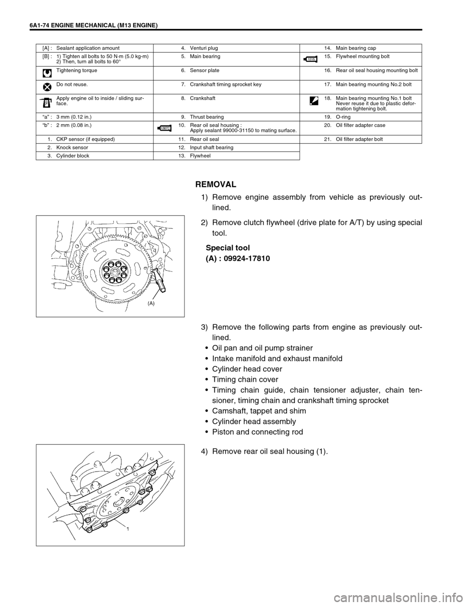
2) Remove clutch flywheel (drive plate for A/T) by using special
tool.
Special tool
(A) : 09924-17810
3) Remove the following parts from engine as previously out-
lined.
Oil pan and oil pump strainer
Intake manifold and exhaust manifold
Cylinder head cover
Timing chain cover
Timing chain guide, chain tensioner adjuster, chain ten-
sioner, timing chain and crankshaft timing sprocket
Camshaft, tappet and shim
Cylinder head assembly
Piston and connecting rod
4) Remove rear oil seal housing (1).
[A] : Sealant application amount 4. Venturi plug 14. Main bearing cap
[B] : 1) Tighten all bolts to 50 N·m (5.0 kg-m)
2) Then, turn all bolts to 60°5. Main bearing 15. Flywheel mounting bolt
Tightening torque 6. Sensor plate 16. Rear oil seal housing mounting bolt
Do not reuse. 7. Crankshaft timing sprocket key 17. Main bearing mounting No.2 bolt
Apply engine oil to inside / sliding sur-
face.8. Crankshaft
18. Main bearing mounting No.1 bolt
Never reuse it due to plastic defor-
mation tightening bolt.
“a” : 3 mm (0.12 in.) 9. Thrust bearing 19. O-ring
“b” : 2 mm (0.08 in.) 10. Rear oil seal housing :
Apply sealant 99000-31150 to mating surface.20. Oil filter adapter case
1. CKP sensor (if equipped) 11. Rear oil seal 21. Oil filter adapter bolt
2. Knock sensor 12. Input shaft bearing
3. Cylinder block 13. Flywheel
Page 582 of 698
ENGINE MECHANICAL (M13 ENGINE) 6A1-81
Rear Oil Seal
Carefully inspect oil seal (1) for wear or damage.
If its lip is worn or damaged, replace it.
For oil seal installation, press-fit rear oil seal (1) to oil seal housing
(2) by using special tool as shown in the figure.
Special tool
(A) : 09911-97820
Drive in dimension
“a” : 3 mm (0.12 in.)
Flywheel
If ring gear is damaged, cracked or worn, replace flywheel.
If the surface contacting clutch disc is damaged, or exces-
sively worn, replace flywheel.
Check flywheel for face runout with a dial gauge.
If runout exceeds its limit, replace flywheel.
Flywheel on runout
Limit : 0.2 mm (0.0079 in.)
Sensor plate
Check sensor plate for crack or damage. If malcondition is
found, replace it.
Page 584 of 698

ENGINE MECHANICAL (M13 ENGINE) 6A1-83
INSTALLATION
1) Install sensor plate (1) to crankshaft (2) and tighten bolts to
specified torque.
Tightening torque
Sensor plate bolts (a) : 11 N·m (1.1 kg-m, 8.0 lb-ft)
2) Install main bearings to cylinder block.
Upper half of bearing (1), has an oil groove (2).
Install it to cylinder block (3), and the other half without oil
groove to bearing cap.
Make sure that two halves are painted in the same color.
3) Install thrust bearings (1) to cylinder block between No.2 and
No.3 cylinders. Face oil groove (2) sides to crank webs.
4) Confirm that dowel pins (3) are installed to intake side of
each journal.
5) Install crankshaft to cylinder block.NOTE:
All parts to be installed must be perfectly clean.
Be sure to oil crankshaft journals, journal bearings,
thrust bearings, crankpins, connecting rod bearings,
pistons, piston rings and cylinder bores.
Journal bearings, bearings caps, connecting rods, rod
bearings, rod bearing caps, pistons and piston rings
are in combination sets. Do not disturb such combina-
tion and make sure that each part goes back to where
it came from, when installing.
NOTE:
When installing sensor plate, align spring pin (3) on
crankshaft and hole of sensor plate.
Page 587 of 698
6A1-86 ENGINE MECHANICAL (M13 ENGINE)
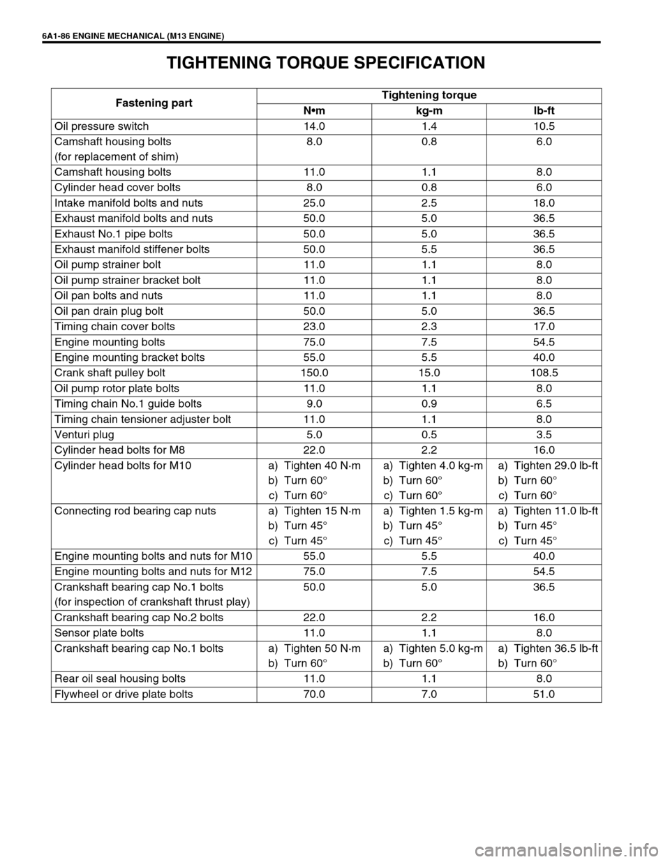
TIGHTENING TORQUE SPECIFICATION
Fastening partTightening torque
Nm kg-m lb-ft
Oil pressure switch 14.0 1.4 10.5
Camshaft housing bolts
(for replacement of shim)8.0 0.8 6.0
Camshaft housing bolts 11.0 1.1 8.0
Cylinder head cover bolts 8.0 0.8 6.0
Intake manifold bolts and nuts 25.0 2.5 18.0
Exhaust manifold bolts and nuts 50.0 5.0 36.5
Exhaust No.1 pipe bolts 50.0 5.0 36.5
Exhaust manifold stiffener bolts 50.0 5.5 36.5
Oil pump strainer bolt 11.0 1.1 8.0
Oil pump strainer bracket bolt 11.0 1.1 8.0
Oil pan bolts and nuts 11.0 1.1 8.0
Oil pan drain plug bolt 50.0 5.0 36.5
Timing chain cover bolts 23.0 2.3 17.0
Engine mounting bolts 75.0 7.5 54.5
Engine mounting bracket bolts 55.0 5.5 40.0
Crank shaft pulley bolt 150.0 15.0 108.5
Oil pump rotor plate bolts 11.0 1.1 8.0
Timing chain No.1 guide bolts 9.0 0.9 6.5
Timing chain tensioner adjuster bolt 11.0 1.1 8.0
Venturi plug 5.0 0.5 3.5
Cylinder head bolts for M8 22.0 2.2 16.0
Cylinder head bolts for M10 a) Tighten 40 N·m
b) Turn 60°
c) Turn 60°a) Tighten 4.0 kg-m
b) Turn 60°
c) Turn 60°a) Tighten 29.0 lb-ft
b) Turn 60°
c) Turn 60°
Connecting rod bearing cap nuts a) Tighten 15 N·m
b) Turn 45°
c) Turn 45°a) Tighten 1.5 kg-m
b) Turn 45°
c) Turn 45°a) Tighten 11.0 lb-ft
b) Turn 45°
c) Turn 45°
Engine mounting bolts and nuts for M10 55.0 5.5 40.0
Engine mounting bolts and nuts for M12 75.0 7.5 54.5
Crankshaft bearing cap No.1 bolts
(for inspection of crankshaft thrust play)50.0 5.0 36.5
Crankshaft bearing cap No.2 bolts 22.0 2.2 16.0
Sensor plate bolts 11.0 1.1 8.0
Crankshaft bearing cap No.1 bolts a) Tighten 50 N·m
b) Turn 60°a) Tighten 5.0 kg-m
b) Turn 60°a) Tighten 36.5 lb-ft
b) Turn 60°
Rear oil seal housing bolts 11.0 1.1 8.0
Flywheel or drive plate bolts 70.0 7.0 51.0
Page 590 of 698
ENGINE COOLING 6B-1
6B
SECTION 6B
ENGINE COOLING
CONTENTS
GENERAL DESCRIPTION ...............................6B-2
COOLING SYSTEM CIRCULATION............. 6B-2
COOLANT ..................................................... 6B-3
DIAGNOSIS ......................................................6B-4
DIAGNOSIS TABLE ...................................... 6B-4
SYSTEM CIRCUIT ........................................ 6B-5
SYSTEM CIRCUIT INSPECTION ................. 6B-5
MAINTENANCE................................................6B-6
COOLANT LEVEL CHECK ........................... 6B-6
ENGINE COOLING SYSTEM
INSPECTION AND SERVICE ....................... 6B-7
COOLING SYSTEM FLUSH AND REFILL ... 6B-7
WATER PUMP/GENERATOR DRIVE
BELT TENSION INSPECTION AND
ADJUSTMENT .............................................. 6B-9
ON-VEHICLE SERVICE .................................6B-10SYSTEM COMPONENTS .......................... 6B-10
COOLING SYSTEM DRAINING ................. 6B-11
COOLING SYSTEM REFILL ...................... 6B-11
COOLING WATER PIPES OR HOSES ...... 6B-12
THERMOSTAT ........................................... 6B-12
RADIATOR ................................................. 6B-14
RADIATOR AND CONDENSER
COOLING FAN ........................................... 6B-15
RADIATOR AND CONDENSER
COOLING FAN RELAY .............................. 6B-15
WATER PUMP/GENERATOR
DRIVE BELT ............................................... 6B-15
WATER PUMP............................................ 6B-16
ECT SENSOR............................................. 6B-18
REQUIRED SERVICE MATERIAL................. 6B-18
TIGHTENING TORQUE SPECIFICATION..... 6B-18
Page 593 of 698
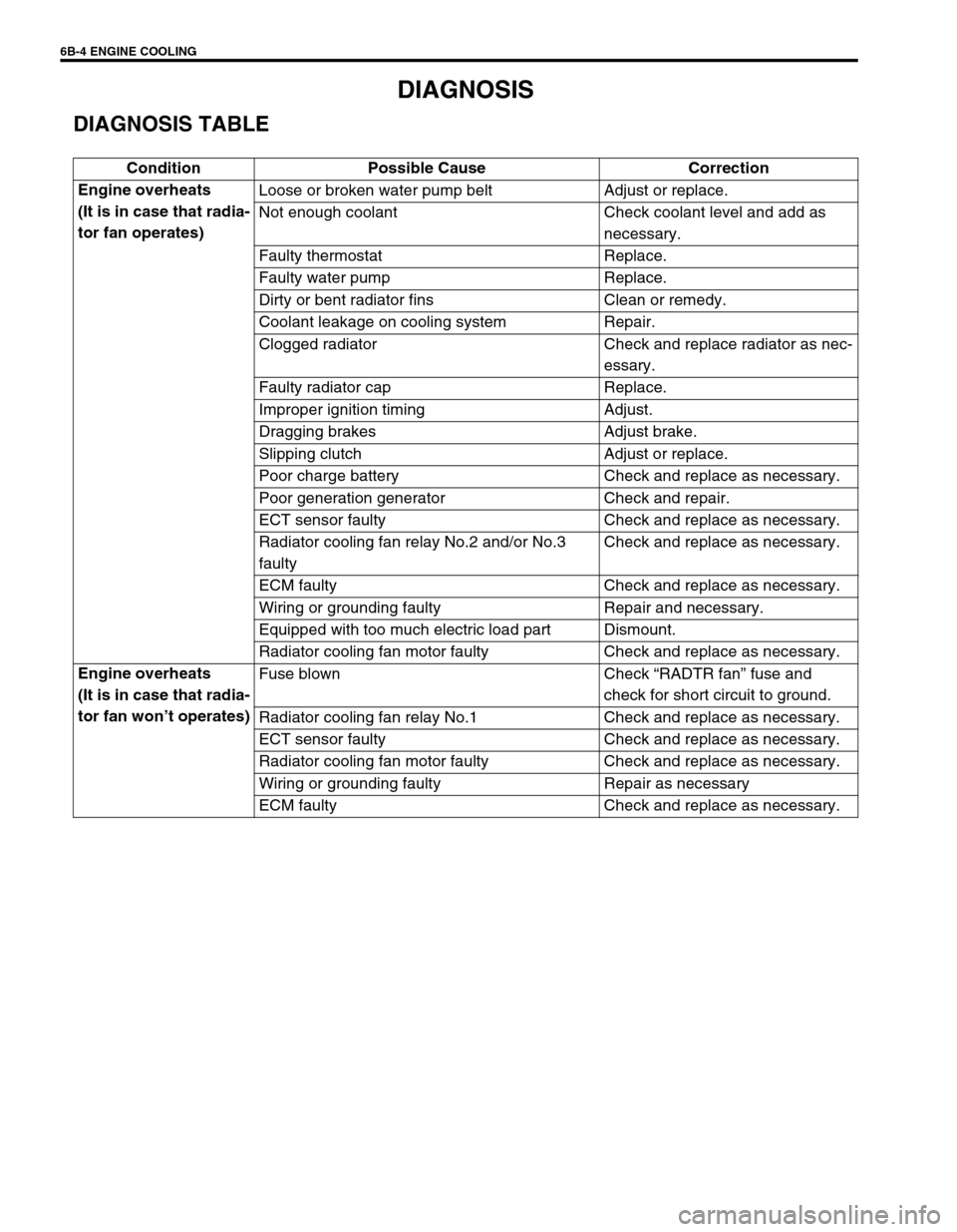
6B-4 ENGINE COOLING
DIAGNOSIS
DIAGNOSIS TABLE
Condition Possible Cause Correction
Engine overheats
(It is in case that radia-
tor fan operates)Loose or broken water pump belt Adjust or replace.
Not enough coolant Check coolant level and add as
necessary.
Faulty thermostat Replace.
Faulty water pump Replace.
Dirty or bent radiator fins Clean or remedy.
Coolant leakage on cooling system Repair.
Clogged radiator Check and replace radiator as nec-
essary.
Faulty radiator cap Replace.
Improper ignition timing Adjust.
Dragging brakes Adjust brake.
Slipping clutch Adjust or replace.
Poor charge battery Check and replace as necessary.
Poor generation generator Check and repair.
ECT sensor faulty Check and replace as necessary.
Radiator cooling fan relay No.2 and/or No.3
faultyCheck and replace as necessary.
ECM faulty Check and replace as necessary.
Wiring or grounding faulty Repair and necessary.
Equipped with too much electric load part Dismount.
Radiator cooling fan motor faulty Check and replace as necessary.
Engine overheats
(It is in case that radia-
tor fan won’t operates)Fuse blown Check “RADTR fan” fuse and
check for short circuit to ground.
Radiator cooling fan relay No.1 Check and replace as necessary.
ECT sensor faulty Check and replace as necessary.
Radiator cooling fan motor faulty Check and replace as necessary.
Wiring or grounding faulty Repair as necessary
ECM faulty Check and replace as necessary.
Page 594 of 698
ENGINE COOLING 6B-5
SYSTEM CIRCUIT
SYSTEM CIRCUIT INSPECTION
Refer to “RADIATOR COOLINGFAN CONTROL SYSTEM CHECK” in Section 6
1. Main fuse box 6. ECM main fuse 11. Radiator and condenser cooling fan motor
2. Generator 7. ECM main relay 12. Refrigerant pressure triple switch (if equipped with A/C)
3. Battery 8. Radiator and condenser cooling fan relay No.1 13. ECT sensor
4. Battery fuse 9. Radiator and condenser cooling fan relay No.2 14. ECM
5. RADTR fuse 10. Radiator and condenser cooling fan relay No.3 15. TO A/C switch
ACG
15A 30A
BLU/WHT
BLK/YEL
BLK
BLU
ORN
BLK
BLK
BLUH–
H+
L– L+
GRN/BLK
BLU/BLK
BRN/WHT
YEL/GRN
PNK/GRN
PPL/YEL
LT GRN/BLK
BLK/RED
BLK/RED 80A
145
6
2
3
7
8
9
11
10
13 15
12
14