Page 534 of 698
ENGINE MECHANICAL (M13 ENGINE) 6A1-33
ASSEMBLY
1) Wash, clean and then dry all disassembled parts.
2) Apply thin coat of engine oil to inner and outer rotors, oil seal
lip portion, and inside surfaces of oil pump case and plate.
3) Install outer (1) and inner rotors (2) to oil pump case.
4) Install relief valve component (1) to rotor plate (2).
5) Install rotor plate and tighten all bolts to specified torque.
After installing plate, check to be sure that rotors turn
smoothly by hand (0.3 N·m (0.03 kg-m, 0.25 lb-ft) torque or
below).
Tightening torque
Oil pump rotor plate bolts (a) : 11 N·m (1.1 kg-m, 8.0 lb-ft)
INSTALLATION
For installation referring to “TIMING CHAIN COVER”.
Page 535 of 698

6A1-34 ENGINE MECHANICAL (M13 ENGINE)
TIMING CHAIN AND CHAIN TENSIONER
REMOVAL
1) Disconnect negative cable at battery.
2) Drain engine oil.
3) Remove oil pan referring to “OIL PAN AND OIL PUMP
STRAINER”.
4) Remove cylinder head cover referring to “CYLINDER HEAD
COVER”.
5) Remove timing chain cover referring to “TIMING CHAIN
COVER”.
6) Align both intake and exhaust camshaft timing sprocket
marks (1) with notches (2) of cylinder head respectively by
turning crankshaft.
7) Remove timing chain tensioner adjuster assembly (3).
8) Remove timing chain tensioner (4).
9) Remove timing chain No.1 guide (5).
10) Remove timing chain (6) with crankshaft timing sprocket (7).
1. Crankshaft timing sprocket 4. Timing chain tensioner
: Apply engine oil to sliding surface.7. Chain tensioner mounting bolt
2. Timing chain
: Apply engine oil.5. Timing chain tensioner adjuster assembly 8. Chain guide mounting bolt
3. Timing chain No.1 guide
: Apply engine oil to sliding surface.6. Chain tensioner adjuster mounting bolt Tightening torque
CAUTION:
After timing chain is removed, never turn crankshaft and
camshafts independently more than its allowable turning
range described in “INSTALLATION” section.
If turned, interference may occur between piston and
valves and valves themselves, and parts related to piston
and valves may be damaged.
Page 537 of 698

6A1-36 ENGINE MECHANICAL (M13 ENGINE)
Timing chain No.1 guide
Check shoe (1) for wear or damage.
INSTALLATION
1) Check that match marks (1) on intake and exhaust camshaft
timing sprockets are in match with notches (2) on cylinder
head as shown in figure.
2) Set key (3) and turn crankshaft to position key on upside of
crankshaft.
3) Install timing chain by aligning dark blue plate (1) of timing
chain and triangle mark (2) on camshaft timing sprocket as
shown in figure.
4) Fit crankshaft timing sprocket to timing chain by aligning gold
plate (3) of timing chain and mark (4) on crankshaft timing
sprocket. Then install crankshaft timing sprocket fitted with
chain to crankshaft.
CAUTION:
After timing chain is removed, never turn crankshaft and
camshafts independently more than such an extent (“a”,
“b”) as shown in figure.
If turned, interference may occur between piston and
valves and valves themselves, and parts related to piston
and valves may be damaged.
“a” :90°4. Camshaft (IN and EX) allowable turning range.
By marks on camshaft timing sprocket within 15° from notches on
cylinder head on both right and left.
“b” :15°5. Crankshaft allowable turning range.
By key on crankshaft, within 90° from top on both right and left.
Page 544 of 698

ENGINE MECHANICAL (M13 ENGINE) 6A1-43
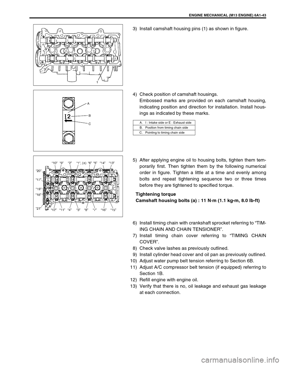
3) Install camshaft housing pins (1) as shown in figure.
4) Check position of camshaft housings.
Embossed marks are provided on each camshaft housing,
indicating position and direction for installation. Install hous-
ings as indicated by these marks.
5) After applying engine oil to housing bolts, tighten them tem-
porarily first. Then tighten them by the following numerical
order in figure. Tighten a little at a time and evenly among
bolts and repeat tightening sequence two or three times
before they are tightened to specified torque.
Tightening torque
Camshaft housing bolts (a) : 11 N·m (1.1 kg-m, 8.0 lb-ft)
6) Install timing chain with crankshaft sprocket referring to “TIM-
ING CHAIN AND CHAIN TENSIONER”.
7) Install timing chain cover referring to “TIMING CHAIN
COVER”.
8) Check valve lashes as previously outlined.
9) Install cylinder head cover and oil pan as previously outlined.
10) Adjust water pump belt tension referring to Section 6B.
11) Adjust A/C compressor belt tension (if equipped) referring to
Section 1B.
12) Refill engine with engine oil.
13) Verify that there is no, oil leakage and exhaust gas leakage
at each connection.
A. I : Intake side or E : Exhaust side
B. Position from timing chain side
C. Pointing to timing chain side
Page 545 of 698
6A1-44 ENGINE MECHANICAL (M13 ENGINE)
VALVES AND CYLINDER HEAD
REMOVAL
1) Relieve fuel pressure according to procedure described in
Section 6.
2) Disconnect negative cable at battery.
3) Drain engine oil.
[A]✱1) Tighten all bolts at 40 N·m (4.0 kg-m)
2) Turn all bolts at 60°
3) Then, Turn all bolt at 60° once again6. Intake valve 12. Knock pin
1. Valve cotters 7. Exhaust valve
Tightening torque
2. Valve spring retainer 8. Valve guide
Do not reuse.
3. Valve spring 9. Cylinder head bolt
: Never reuse it due to plastic deformation
tightening bolt.Apply engine oil to sliding surface of
each part.
4. Valve stem seal 10. Cylinder head
5. Valve spring seat 11. Cylinder head gasket
: “TOP” mark provided on gasket comes to
crankshaft pulley side, facing up.
Page 546 of 698

ENGINE MECHANICAL (M13 ENGINE) 6A1-45
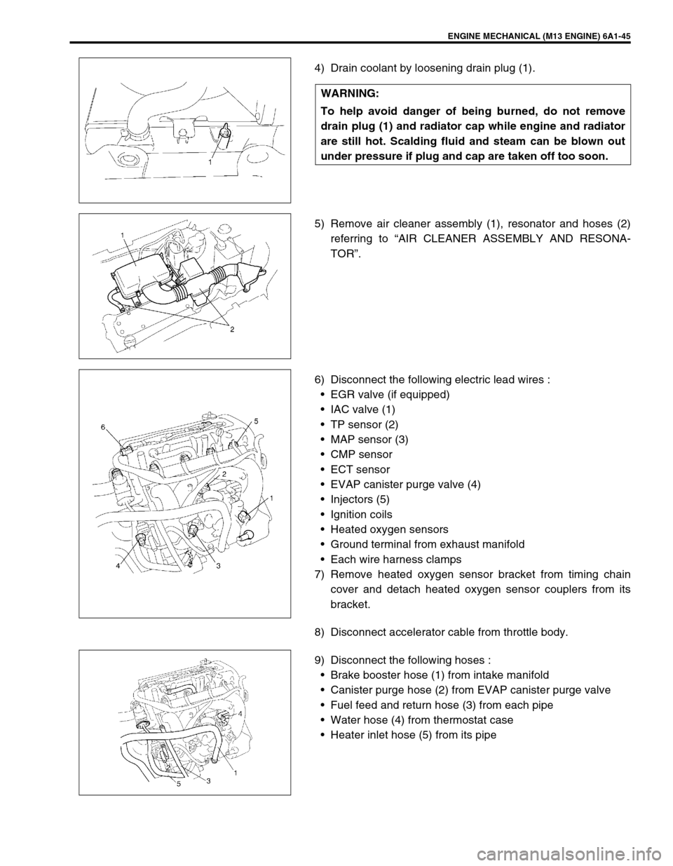
4) Drain coolant by loosening drain plug (1).
5) Remove air cleaner assembly (1), resonator and hoses (2)
referring to “AIR CLEANER ASSEMBLY AND RESONA-
TOR”.
6) Disconnect the following electric lead wires :
EGR valve (if equipped)
IAC valve (1)
TP sensor (2)
MAP sensor (3)
CMP sensor
ECT sensor
EVAP canister purge valve (4)
Injectors (5)
Ignition coils
Heated oxygen sensors
Ground terminal from exhaust manifold
Each wire harness clamps
7) Remove heated oxygen sensor bracket from timing chain
cover and detach heated oxygen sensor couplers from its
bracket.
8) Disconnect accelerator cable from throttle body.
9) Disconnect the following hoses :
Brake booster hose (1) from intake manifold
Canister purge hose (2) from EVAP canister purge valve
Fuel feed and return hose (3) from each pipe
Water hose (4) from thermostat case
Heater inlet hose (5) from its pipe WARNING:
To help avoid danger of being burned, do not remove
drain plug (1) and radiator cap while engine and radiator
are still hot. Scalding fluid and steam can be blown out
under pressure if plug and cap are taken off too soon.
Page 548 of 698

ENGINE MECHANICAL (M13 ENGINE) 6A1-47
DISASSEMBLY
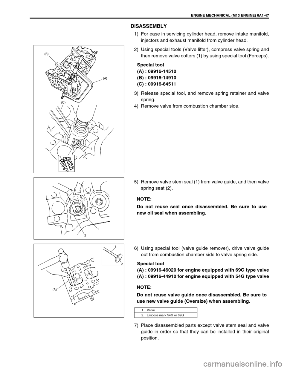
1) For ease in servicing cylinder head, remove intake manifold,
injectors and exhaust manifold from cylinder head.
2) Using special tools (Valve lifter), compress valve spring and
then remove valve cotters (1) by using special tool (Forceps).
Special tool
(A) : 09916-14510
(B) : 09916-14910
(C) : 09916-84511
3) Release special tool, and remove spring retainer and valve
spring.
4) Remove valve from combustion chamber side.
5) Remove valve stem seal (1) from valve guide, and then valve
spring seat (2).
6) Using special tool (valve guide remover), drive valve guide
out from combustion chamber side to valve spring side.
Special tool
(A) : 09916-46020 for engine equipped with 69G type valve
(A) : 09916-44910 for engine equipped with 54G type valve
7) Place disassembled parts except valve stem seal and valve
guide in order so that they can be installed in their original
position.
NOTE:
Do not reuse seal once disassembled. Be sure to use
new oil seal when assembling.
NOTE:
Do not reuse valve guide once disassembled. Be sure to
use new valve guide (Oversize) when assembling.
1. Valve
2. Emboss mark 54G or 69G
Page 549 of 698

6A1-48 ENGINE MECHANICAL (M13 ENGINE)
INSPECTION
Valve Guides
Using a micrometer and bore gauge, take diameter readings on
valve stems and guides to check stem-to-guide clearance. Be
sure to take reading at more than one place along the length of
each stem and guide.
If clearance exceeds limit, replace valve and valve guide.
Valve stem-to-guide clearance
Valve stem diameter [A]
Valve guide bore [B] standard
In and Ex : 6.000 – 6.012 mm (0.2362 – 0.2367 in.) for 69G
type valve
In and Ex : 5.485 – 5.510 mm (0.2159 – 0.2169 in.) for 54G
type valve
If bore gauge is not available, check end deflection of valve stem
with a dial gauge instead.
Move stem end in directions (1) and (2) to measure end deflec-
tion.
If deflection exceeds its limit, replace valve stem and valve guide.
Valve stem end deflection limit
In : 0.14 mm (0.005 in.)
Ex : 0.18 mm (0.007 in.)Valve type Standard Limit
69GIn0.020 – 0.047 mm
(0.0008 – 0.0019 in.)0.07 mm
(0.0028 in.)
Ex0.045 – 0.072 mm
(0.0018 – 0.0028 in.)0.09 mm
(0.0035 in.)
54GIn0.020 – 0.030 mm
(0.0008 – 0.0012 in.)0.05 mm
(0.0017 in.)
Ex0.045 – 0.055 mm
(0.0018 – 0.0022 in.)0.07 mm
(0.0028 in.)
Valve type Standard
69GIn5.965 – 5.980 mm
(0.2348 – 0.2354 in.)
Ex5.940 – 5.955 mm
(0.2339 – 0.2344 in.)
54GIn5.465 – 5.480 mm
(0.2152 – 0.2157 in.)
Ex5.440 – 5.455 mm
(0.2142 – 0.2148 in.)
1. Emboss mark 54G or 69G