Page 306 of 698
BRAKES 5-33
BRAKE BACK PLATE (FOR 4WD VEHICLE)
REMOVAL AND INSTALLATION
Refer to “REAR AXLE SHAFT AND WHEEL BEARING (4WD VEHICLE)” in Section 3E.
MASTER CYLINDER
MASTER CYLINDER RESERVOIR
REMOVAL
1) Remove master cylinder.
2) Pull out retainer (1) and remove reservoir (2).
1. Reservoir tank 9. Sleeve Tightening torque
2. Retainer 10. Primary piston
: Apply brake fluid to contact surface of cup.Do not reuse.
3. Grommet
: Apply brake fluid.11. Primary cup
: Confirm installing direction.
4. Master cylinder body 12. Washer
5. Secondary return spring 13. Cap
6. Secondary cup
: Confirm installing direction Size of cup : 6=11>14>8 .14. Cap cup
: Confirm installing direction.
7. Secondary piston
: Apply brake fluid to contact surface of cup.15. Master cylinder gasket
8. Sleeve cup
: Confirm installing direction.
2
1
Page 307 of 698
5-34 BRAKES
INSTALLATION
1) Apply brake fluid to new grommets and attach grommets (2)
to master cylinder (1).
2) Install reservoir (2) to master cylinder and insert retainer (1).
3) Install master cylinder.
4) Fill reservoir with specified brake fluid up to MAX mark on it.
5) After installation, purge air and check for brake fluid leakage.
MASTER CYLINDER ASSEMBLY
REMOVAL
1) Clean outside of master cylinder.
2) Drain brake fluid in reservoir.
3) Disconnect fluid level switch coupler (1) on reservoir.
4) Disconnect brake pipes (2) connected to master cylinder.
5) Remove master cylinder fixing nuts (3).
6) Remove master cylinder and master cylinder gasket.NOTE:
Be sure to use new grommets.
1 2
2
1
CAUTION:
Do not allow brake fluid to get on painted surface.
Painted surface will be damaged by brake fluid, flush it
with water immediately if any fluid is spilled.
13
MAX
MIN
2
3
Page 308 of 698

BRAKES 5-35
INSPECTION
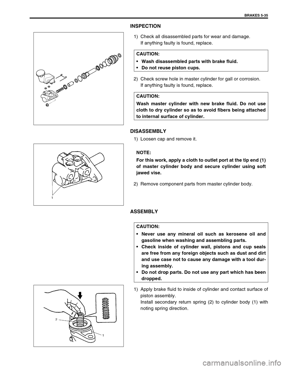
1) Check all disassembled parts for wear and damage.
If anything faulty is found, replace.
2) Check screw hole in master cylinder for gall or corrosion.
If anything faulty is found, replace.
DISASSEMBLY
1) Loosen cap and remove it.
2) Remove component parts from master cylinder body.
ASSEMBLY
1) Apply brake fluid to inside of cylinder and contact surface of
piston assembly.
Install secondary return spring (2) to cylinder body (1) with
noting spring direction. CAUTION:
Wash disassembled parts with brake fluid.
Do not reuse piston cups.
CAUTION:
Wash master cylinder with new brake fluid. Do not use
cloth to dry cylinder so as to avoid fibers being attached
to internal surface of cylinder.
NOTE:
For this work, apply a cloth to outlet port at the tip end (1)
of master cylinder body and secure cylinder using soft
jawed vise.
CAUTION:
Never use any mineral oil such as kerosene oil and
gasoline when washing and assembling parts.
Check inside of cylinder wall, pistons and cup seals
are free from any foreign objects such as dust and dirt
and use case not to cause any damage with a tool dur-
ing assembly.
Do not drop parts. Do not use any part which has been
dropped.
Page 309 of 698
5-36 BRAKES
2) Attach secondary cup (1) to secondary piston (2), they install
it to cylinder body such a direction as shown.
3) Push secondary cup to the bottom by using special tool.
Special tool
(A) : 09951-18220
4) Remove O-ring (1) from sleeve (2).
Special tool
(A) : 09900-06106
5) Install sleeve cup (3) and O-ring (2) to sleeve (1) such a
direction as shown.
6) Install sleeve assembly with aligning protrusion (1) of sleeve
and dent (2) of cylinder body. NOTE:
Secondary cup is the same as primary cup.
Diameter of secondary cup is the largest compared
with sleeve cup and cap cup.
(A)
CAUTION:
Do not cause any damage to inside of sleeve.
If caused, replace primary piston assembly.
NOTE:
Diameter of sleeve cup and O-ring are smaller than
those of cap.
O-ring is the same as that of smaller one of cap O-ring.
Page 310 of 698
BRAKES 5-37
7) Install cup (1) and washer (2) such a direction as shown.
8) Remove cap cup (1) from cap with caring not to cause any
damage to inside of cap (2).
9) Install cap cup and O-rings (3) to cap such a direction as
shown.
10) Install cap and tighten it to specified torque, then confirm the
length “A”.
Tightening torque
Cap (a) : 14 N·m (1.4 kg-m, 10.5 lb-ft)
Cap installation position
“A” : Less than 26 mm (1.02 in.)
INSPECTION AFTER ASSEMBLY
1) Install radiator cap test with special tool to master cylinder
port (1).
Special tool
(A) : 09952-46010
(B) : 09952-26020
2) Apply air and confirm that pressure is not applied.NOTE:
Primary cup is the same as secondary cup.
Primary cup is the largest compared with that of cap
and sleeve.
NOTE:
For without ABS vehicle, install special tool (B) to oppo-
site side port (2).
1(B)
2 (A)
Page 311 of 698

5-38 BRAKES
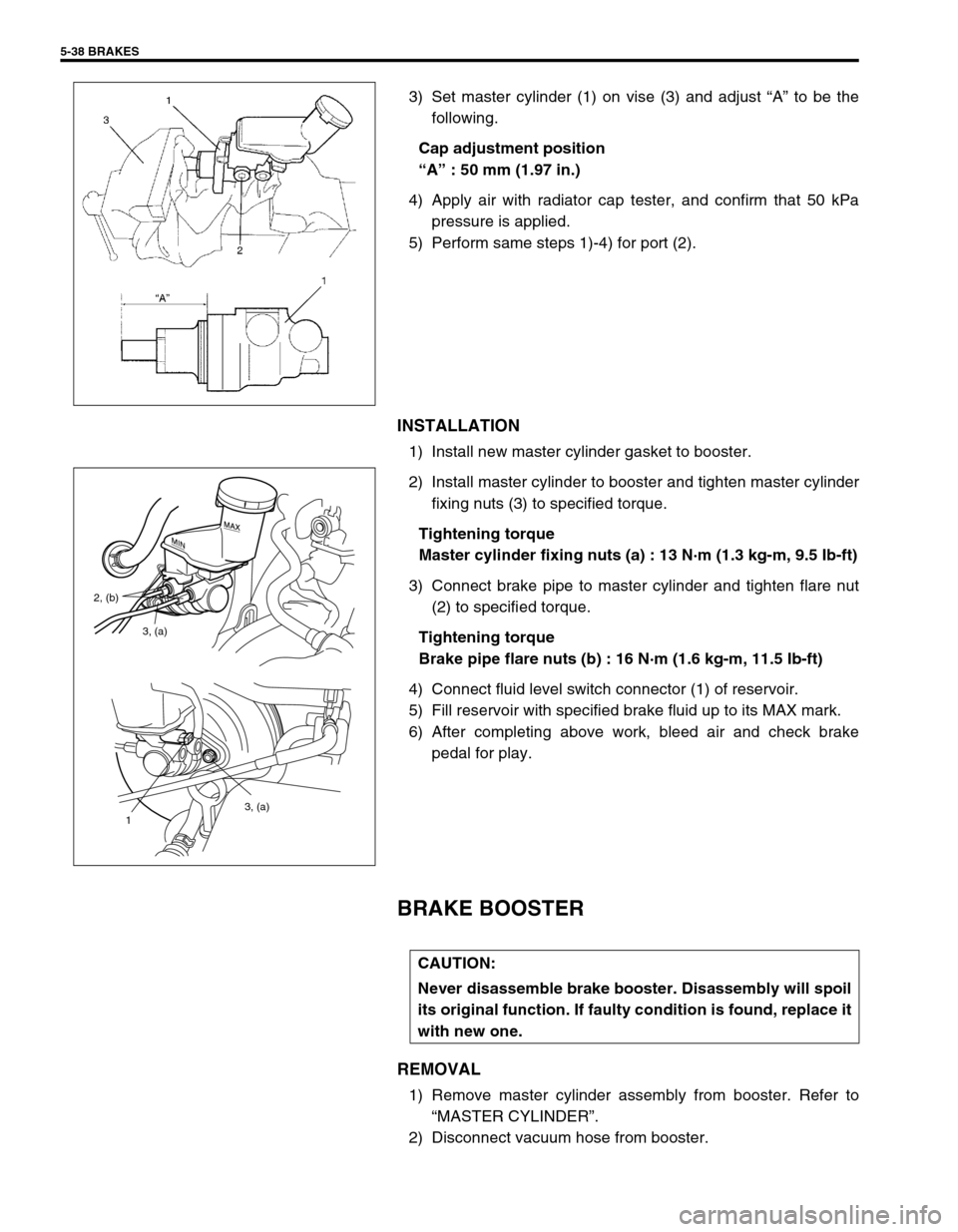
3) Set master cylinder (1) on vise (3) and adjust “A” to be the
following.
Cap adjustment position
“A” : 50 mm (1.97 in.)
4) Apply air with radiator cap tester, and confirm that 50 kPa
pressure is applied.
5) Perform same steps 1)-4) for port (2).
INSTALLATION
1) Install new master cylinder gasket to booster.
2) Install master cylinder to booster and tighten master cylinder
fixing nuts (3) to specified torque.
Tightening torque
Master cylinder fixing nuts (a) : 13 N·m (1.3 kg-m, 9.5 Ib-ft)
3) Connect brake pipe to master cylinder and tighten flare nut
(2) to specified torque.
Tightening torque
Brake pipe flare nuts (b) : 16 N·m (1.6 kg-m, 11.5 Ib-ft)
4) Connect fluid level switch connector (1) of reservoir.
5) Fill reservoir with specified brake fluid up to its MAX mark.
6) After completing above work, bleed air and check brake
pedal for play.
BRAKE BOOSTER
REMOVAL
1) Remove master cylinder assembly from booster. Refer to
“MASTER CYLINDER”.
2) Disconnect vacuum hose from booster.
3, (a)
1
3, (a) 2, (b)
CAUTION:
Never disassemble brake booster. Disassembly will spoil
its original function. If faulty condition is found, replace it
with new one.
Page 312 of 698

BRAKES 5-39
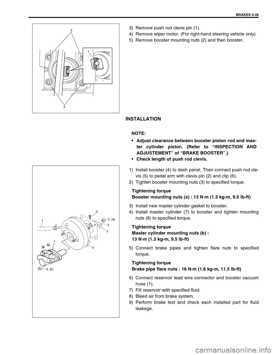
3) Remove push rod clevis pin (1).
4) Remove wiper motor. (For right-hand steering vehicle only)
5) Remove booster mounting nuts (2) and then booster.
INSTALLATION
1) Install booster (4) to dash panel. Then connect push rod cle-
vis (5) to pedal arm with clevis pin (2) and clip (6).
2) Tighten booster mounting nuts (3) to specified torque.
Tightening torque
Booster mounting nuts (a) : 13 N·m (1.3 kg-m, 9.5 lb-ft)
3) Install new master cylinder gasket to booster.
4) Install master cylinder (7) to booster and tighten mounting
nuts (8) to specified torque.
Tightening torque
Master cylinder mounting nuts (b) :
13 N·m (1.3 kg-m, 9.5 lb-ft)
5) Connect brake pipes and tighten flare nuts to specified
torque.
Tightening torque
Brake pipe flare nuts : 16 N·m (1.6 kg-m, 11.5 lb-ft)
6) Connect reservoir lead wire connector and booster vacuum
hose (1).
7) Fill reservoir with specified fluid.
8) Bleed air from brake system.
9) Perform brake test and check each installed part for fluid
leakage.
1
2
2
NOTE:
Adjust clearance between booster piston rod and mas-
ter cylinder piston. (Refer to “INSPECTION AND
ADJUSTEMENT” of “BRAKE BOOSTER”.)
Check length of push rod clevis.
Page 313 of 698

5-40 BRAKES
INSPECTION AND ADJUSTMENT
Installation Position Of Push Rod
If push rod clevis (1) has been removed, adjust distance between
booster installation surface (without including packing) and the
center of clevis pin hole to standard value “a” and tighten nut (2)
to specified torque.
Distance “a” between center of booster clevis pin hole
and booster surface
Standard : 97 - 98 mm (3.82 - 3.86 in.)
Tightening torque
Clevis pin lock nut (a) : 19 N·m (1.9 kg-m, 14.0 lb-ft)
Clearance Between Booster Piston Rod And Master Cylin-
der Piston
The length of booster piston rod (1) is adjusted to provide speci-
fied clearance “a” between piston rod (1) end and master cylinder
piston (2).
Before measuring clearance, push piston rod several times
so as to make sure reaction disc is in place.
Keep inside of booster at atmospheric pressure for measure-
ment.
Measure length “a” of piston rod, i.e. distance between piston rod
and mating surface of booster-to-master cylinder.
Length “a” of piston rod
: 30.3 - 30.5 mm (1.193 - 1.200 in.)
If measurement is out of specification, adjust piston rod by turning
adjusting screw of piston rod.
Special tool
(B) : 09952-16020
NOTE:
Remove gasket from booster, if equipped.