Page 499 of 801
YH4
GRAND
VITARA
1. Speed sensor assembly
2. Transfer
7D-4 TRANSFER
SPEEDOMETER DRIVEN GEAR
REMOVAL
1) Lift up vehicle horizontally or rear up.
2) Disconnect speed sensor coupler at transfer case.
3) Remove bolt and take off speed sensor from transfer.
INSTALLATION
1) Make sure that O-ring and speed sensor have not been dam-
aged.
2) Inspect speedometer driven gear for abnormal wear of gear
teeth or bend of shaft portion and replace it if necessary.
3) Make sure its smooth rotation.
4) Install speed sensor assembly to transfer and connect coupler
as it was.
Tightening Torque
(a): 6 N
.m (0.6 kg-m, 4.5 lb-ft)
ENGINE REAR MOUNTING
Refer to ªON-VEHICLE SERVICEº of Section 7A.
Page 501 of 801
YH4
GRAND
VITARA
1. Bolt
2. Transfer assembly
1. Bolt
2. Engine rear mounting3. Transfer assembly
1. Bolt
2. Transfer assembly
3. Transmission jack
7D-6 TRANSFER
IN CABIN
Remove gear shift lever case and then remove transfer center case
bolt.
ON LIFT
1) Remove transfer mounting (engine rear mounting) by removing
bolts.
2) Apply transmission jack to transfer to support it.
3) Remove couplers for 4WD / 4WD-LOW switches lead.
4) Remove transfer front case bolts.
5) With transfer assembly supported with transmission jack, slide
it rearward and when it is apart from transmission, lower it.
REMOUNTING
For remounting, reverse dismounting procedure described above,
noting following.
�Be sure to use specified torque for tightening.
�Clamp wiring and breather hose securely.
�Clamp shift lever boot securely.
�Fill specified gear oil by specified amount.
�Connect battery and check for function.
Page 507 of 801

YH4
GRAND
VITARA
DIFFERENTIAL (FRONT) 7E-5
DIAGNOSIS
DIAGNOSIS TABLE
Differential Assembly
ConditionPossible CauseCorrection
Gear noise�Deteriorated or water mixed lubricant
�Inadequate or insufficient lubricant
�Maladjusted backlash between bevel
pinion and gear
�Improper tooth contact in the mesh between
bevel pinion and gear
�Loose bevel gear securing bolts
�Damaged side gear(s) or side pinion(s)Repair and replenish
Repair and replenish
Adjust
Adjust or replace
Replace or retighten
Replace
Bearing noise�(Constant noise) Deteriorated or water
mixed lubricant
�(Constant noise) Inadequate or insufficient
lubricant
�(Noise while coasting) Damaged bearing(s)
of bevel pinion
�(Noise while turning) Damaged diff. side
bearing(s) or axle bearing(s)Repair and replenish
Repair and replenish
Replace
Replace
Oil leakage�Worn or damaged oil seal
�Excessive oil
�Loose differential carrier boltsReplace
Adjust oil level
Replace or retighten
2WD / 4WD
switching error�Defective actuator
�Abnormality in 4WD control systemReplace
Inspect referring to ª4WD
CONTROL SYSTEM DIAG-
NOSTIC FLOW TABLEº.
4WD Control System Diagnostic Flow Table
Before performing the trouble diagnosis, check that the transfer and front differential are in good condition and
there is no air leakage from air hoses and the actuator. Refer to ªON-VEHICLE SERVICEº in this section for air
leakage.
[NOTES ON SYSTEM CIRCUIT INSPECTION]
�Be sure to read ªPrecautions for Electrical Circuit Serviceº in Section 0A before circuit inspection and observe
what is written there.
�For system circuit, refer to the figure of ªGENERAL DESCRIPTIONº in this section.
�For terminal arrangement, refer to ª4WD Control Circuit Inspectionº in this section.
Page 518 of 801
YH4
GRAND
VITARA
7E-16 DIFFERENTIAL (FRONT)
(a)
(a)
(a)
1. Drive shaft joint R
2. Differential housing3. Transmission jack
4. Screw driver
8) Using 2 large screwdrivers as levers, pull out right side drive
shaft joint from differential and dismount housing assembly from
vehicle.
CAUTION:
During above work, use care not to cause damage to
drive shaft boot.
REMOUNTING
For remounting, reverse dismounting procedure and use following
tightening torque.
Tightening Torque
(a): 50 N
.m (5.0 kg-m, 36.5 lb-ft)
After tightening all fasteners properly, fill hypoid gear oil as speci-
fied and check tightening of plugs with specification.
Page 521 of 801
YH4
GRAND
VITARA
7F-2 DIFFERENTIAL (REAR)
DIAGNOSIS
ConditionPossible CauseCorrection
Gear noise�Deteriorated or water mixed lubricant
�Inadequate or insufficient lubricant
�Maladjusted backlash between bevel
pinion and gear
�Improper tooth contact in the mesh between
bevel pinion and gear
�Loose bevel gear securing bolts
�Damaged side gear(s) or side pinion(s)Repair and replenish
Repair and replenish
Adjust as prescribed
Adjust or replace
Replace or retighten
Replace
Bearing noise�(Constant noise) Deteriorated or water
mixed lubricant
�(Constant noise) Inadequate or insufficient
lubricant
�(Noise while coasting) Damaged bearing(s)
of bevel pinion
�(Noise while turning) Damaged diff. side
bearing(s) or axle bearing(s)Repair and replenish
Repair and replenish
Replace
Replace
Oil leakage�Clogged breather plug
�Worn or damaged oil seal
�Excessive oilClean
Replace
Adjust oil level
Page 538 of 801
YH4
GRAND
VITARA
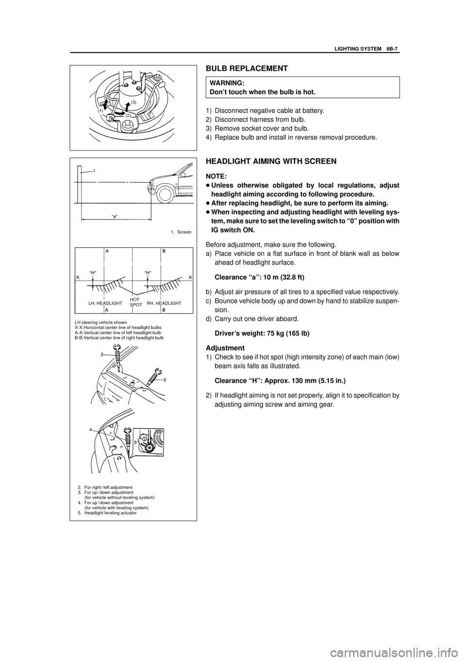
LH steering vehicle shown
X-X:Horizontal center line of headlight bulbs
A-A:Vertical center line of left headlight bulb
B-B:Vertical center line of right headlight bulb1. Screen
2. For right / left adjustment
3. For up / down adjustment
(for vehicle without leveling system)
4. For up / down adjustment
(for vehicle with leveling system)
5. Headlight leveling actuatorHOT
SPOT LH. HEADLIGHT RH. HEADLIGHT
LIGHTING SYSTEM 8B-7
BULB REPLACEMENT
WARNING:
Don't touch when the bulb is hot.
1) Disconnect negative cable at battery.
2) Disconnect harness from bulb.
3) Remove socket cover and bulb.
4) Replace bulb and install in reverse removal procedure.
HEADLIGHT AIMING WITH SCREEN
NOTE:
�Unless otherwise obligated by local regulations, adjust
headlight aiming according to following procedure.
�After replacing headlight, be sure to perform its aiming.
�When inspecting and adjusting headlight with leveling sys-
tem, make sure to set the leveling switch to ª0º position with
IG switch ON.
Before adjustment, make sure the following.
a) Place vehicle on a flat surface in front of blank wall as below
ahead of headlight surface.
Clearance ªaº: 10 m (32.8 ft)
b) Adjust air pressure of all tires to a specified value respectively.
c) Bounce vehicle body up and down by hand to stabilize suspen-
sion.
d) Carry out one driver aboard.
Driver's weight: 75 kg (165 lb)
Adjustment
1) Check to see if hot spot (high intensity zone) of each main (low)
beam axis falls as illustrated.
Clearance ªHº: Approx. 130 mm (5.15 in.)
2) If headlight aiming is not set properly, align it to specification by
adjusting aiming screw and aiming gear.


