Page 87 of 801
YH4
GRAND
VITARA
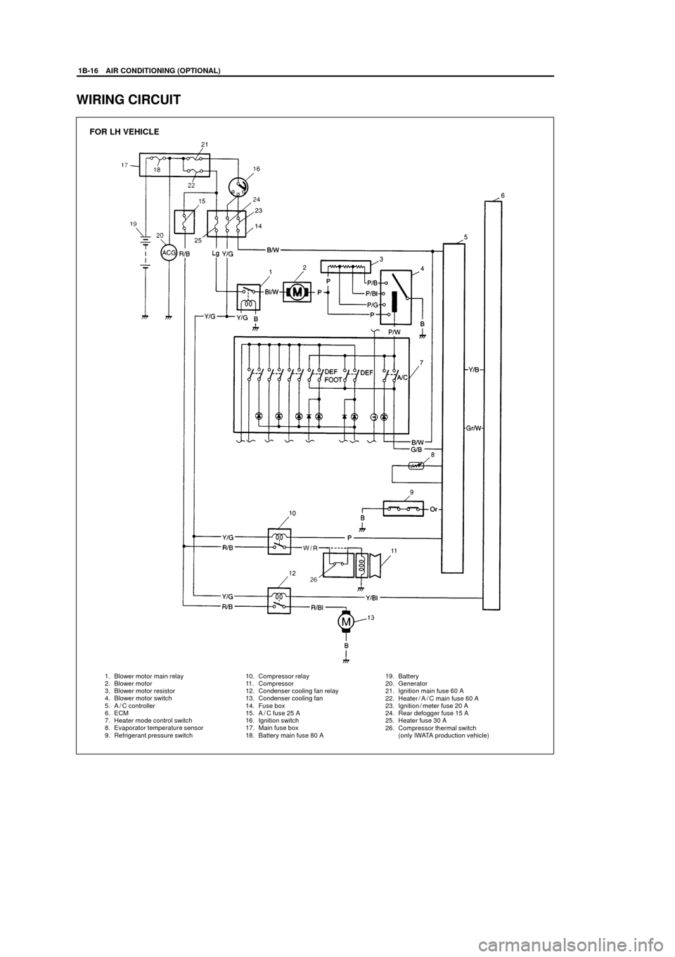
1. Blower motor main relay
2. Blower motor
3. Blower motor resistor
4. Blower motor switch
5. A / C controller
6. ECM
7. Heater mode control switch
8. Evaporator temperature sensor
9. Refrigerant pressure switch10. Compressor relay
11. Compressor
12. Condenser cooling fan relay
13. Condenser cooling fan
14. Fuse box
15. A / C fuse 25 A
16. Ignition switch
17. Main fuse box
18. Battery main fuse 80 A19. Battery
20. Generator
21. Ignition main fuse 60 A
22. Heater/A/C main fuse 60 A
23. Ignition / meter fuse 20 A
24. Rear defogger fuse 15 A
25. Heater fuse 30 A
26. Compressor thermal switch
(only IWATA production vehicle)
FOR LH VEHICLE
1B-16 AIR CONDITIONING (OPTIONAL)
WIRING CIRCUIT
Page 88 of 801
YH4
GRAND
VITARA
AIR CONDITIONING (OPTIONAL) 1B-17
1. Blower motor main relay
2. Blower motor
3. Blower motor resistor
4. Blower motor switch
5. A / C controller
6. ECM
7. Heater mode control switch
8. Evaporator temperature sensor
9. Refrigerant pressure switch
FOR RH VEHICLE
10. Compressor relay
11. Compressor
12. Condenser cooling fan relay
13. Condenser cooling fan
14. Fuse box
15. A / C fuse 25 A
16. Ignition switch
17. Main fuse box
18. Battery main fuse 80 A19. Battery
20. Generator
21. Ignition main fuse 60 A
22. Heater/A/C main fuse 60 A
23. Ignition / meter fuse 20 A
24. Rear defogger fuse 15 A
25. Heater fuse 30 A
26. Compressor thermal switch
(only IWATA production vehicle)
Page 92 of 801
YH4
GRAND
VITARA
AIR CONDITIONING (OPTIONAL) 1B-21
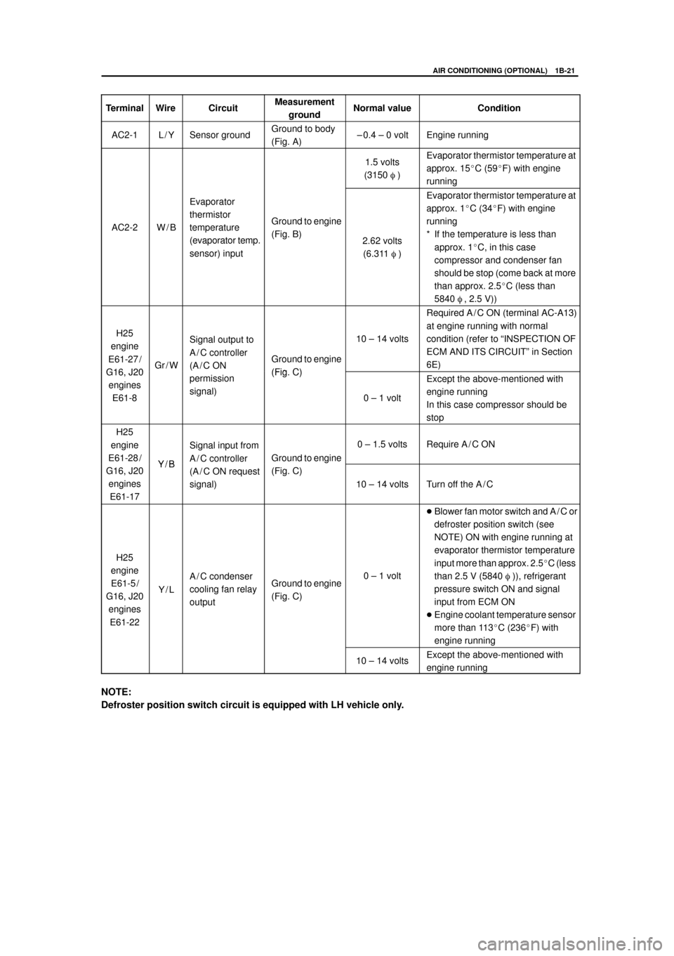
TerminalWireCircuitMeasurement
groundNormal valueCondition
AC2-1L/YSensor groundGround to body
(Fig. A)± 0.4 ± 0 voltEngine running
1.5 volts
(3150 �)Evaporator thermistor temperature at
approx. 15�C (59�F) with engine
running
AC2-2W/B
Evaporator
thermistor
temperature
(evaporator temp.
sensor) input
Ground to engine
(Fig. B)
2.62 volts
(6.311 �)
Evaporator thermistor temperature at
approx. 1�C (34�F) with engine
running
* If the temperature is less than
approx. 1�C, in this case
compressor and condenser fan
should be stop (come back at more
than approx. 2.5�C (less than
5840 �, 2.5 V))
H25
engine
E61-27 /
G16 J20Gr/W
Signal output to
A / C controller
(A / C ON
Ground to engine
(Fig C)
10 ± 14 volts
Required A / C ON (terminal AC-A13)
at engine running with normal
condition (refer to ªINSPECTION OF
ECM AND ITS CIRCUITº in Section
6E)
G16, J20
engines
E61-8
(
permission
signal)(Fig. C)
0 ± 1 volt
Except the above-mentioned with
engine running
In this case compressor should be
stop
H25
engine
E61-28 /
Y/B
Signal input from
A / C controller
Ground to engine
0 ± 1.5 voltsRequire A / C ON
G16, J20
engines
E61-17Y/B(A / C ON request
signal)
g
(Fig. C)
10 ± 14 voltsTurn off the A / C
H25
engine
E61-5 /
G16, J20
engines
E61-22
Y/L
A / C condenser
cooling fan relay
outputGround to engine
(Fig. C)0 ± 1 volt
�Blower fan motor switch and A / C or
defroster position switch (see
NOTE) ON with engine running at
evaporator thermistor temperature
input more than approx. 2.5�C (less
than 2.5 V (5840 �)), refrigerant
pressure switch ON and signal
input from ECM ON
�Engine coolant temperature sensor
more than 113�C (236�F) with
engine running
10 ± 14 voltsExcept the above-mentioned with
engine running
NOTE:
Defroster position switch circuit is equipped with LH vehicle only.
Page 105 of 801
YH4
GRAND
VITARA
3
1B-34 AIR CONDITIONING (OPTIONAL)
5) Disconnect coupler from dual pressure switch (1).
6) Disconnect condenser outlet pipe (3).
7) Disconnect condenser cooling fan motor coupler (2).
8) Remove condenser with fan.
NOTE:
Be careful not to damage fins of condenser and radiator.
9) Remove A / C condenser cooling fan assembly from condenser.
INSTALLATION
Reverse removal sequence to install condenser, noting following
point.
1) When replacing condenser, add 20 to 30 cc of refrigerating oil
from compressor suction-side.
2) Evacuate and charge system according to previously-described
procedure.
Page 106 of 801
YH4
GRAND
VITARA
�
�
1. Air flow
AIR CONDITIONING (OPTIONAL) 1B-35
CONDENSER COOLING FAN ASSEMBLY
INSPECTION
�Remove condenser assembly (Refer to ªA / C CONDENSER AS-
SEMBLY REMOVALº in this section).
�Check continuity between terminal to terminal as shown.
If check results are continuity, proceed to next operation check.
If not, replace.
�Connect battery to condenser fan motor as shown, then check
that the condenser fan motor operates smoothly and specified
current.
Specified current: Maximum 12 A at 12 V
Page 119 of 801
YH4
GRAND
VITARA
3. Compressor and condenser cooling fan fuse
1B-48 AIR CONDITIONING (OPTIONAL)
A / C COMPRESSOR RELAY AND A / C
CONDENSER COOLING FAN RELAY
INSPECTION
1) Disconnect negative (±) cable at battery.
2) Remove condenser cooling fan motor relay (2) and / or compres-
sor relay (1) from vehicle.
3) Check that there is no continuity between terminal ªcº and ªdº.
If there is continuity, replace relay.
4) Connect battery positive (+) terminal to terminal ªbº of relay.
Connect battery negative (±) terminal ªaº of relay.
Check continuity between terminal ªcº and ªdº.
If there is no continuity when relay is connected to the battery,
replace relay.