Page 83 of 118
Downloaded from www.Manualslib.com manuals search engine DIESEL EQUIPMENT
Injectors
13
13-32
Injectors
IT IS FORBIDDEN TO REMOVE THE INTERIOR OF
AN INJECTOR OR TO SEPARATE THE INJECTOR
HOLDER FROM THE PIPE.
IMPORTANT: before any intervention, connect the
after-sales diagnostic tool, query the injection
computer and check that the injection rail is not under
pressure. Take note of the fuel temperature.SPECIAL TOOLING REQUIRED
Elé. 1294 -01 Tool for removing windscreen
wiper arms
Mot. 1383 Tool for removing high pressure
pipes
TIGHTENING TORQUES (in daN.m)
Injector clamp mounting bolt 2 ± 0.2
High pressure pipe nut 2.5 ± 0.2
Page 84 of 118
Downloaded from www.Manualslib.com manuals search engine DIESEL EQUIPMENT
Injectors
13
13-33
REMOVAL
If necessary, remove:
– the bulkhead panel using tool Elé. 1294-01,
– the scuttle panel,
– the air unit.
NOTE: the injectors may be replaced individually.
Remove the HP pipe using the tool Mot. 1383.
Insert the plugs to maintain cleanness.
Remove:
– the injector mounting clamp,
– the injector,
– the flame shield washer.YOU SHOULD FOLLOW THE CLEANNESS INSTRUCTIONS CLOSELY
16192-2S
Page 86 of 118
Downloaded from www.Manualslib.com manuals search engine DIESEL EQUIPMENT
Injectors
13
13-35
NOTE: be careful when refitting that you do not stress the HP pipe. Remove
the injection rail.
Fit:
– the injector,
– the diesel return pipe.
16192-1S
Page 87 of 118
Downloaded from www.Manualslib.com manuals search engine DIESEL EQUIPMENT
Injectors
13
13-36
Fit the high pressure pipe.
Loosen the high pressure pump/rail pipe.
Tighten to torque:
– the injector,
– the injector side connections, then the injection rail connections,
– the rail.
– the pump/rail pipe (high pressure pump side under pressure).
NOTE: it is essential that you replace the fuel return pipe placed on the
injectors during removal.
16192S
After any intervention, check that there are no leaks in the diesel circuit.
Start the engine at idling speed until the fan starts up, then accelerate
several times under no load.
Page 95 of 118
Downloaded from www.Manualslib.com manuals search engine ANTIPOLLUTION
Oil vapour rebreathing
14
14-1
114ANTIPOLLUTION
Oil vapour rebreathing
CIRCUIT DIAGRAM
1Engine
2Oil separator
3Air filter unit
4Inlet manifold
CHECKING
To ensure the correct operation of the anti-pollution
system, the oil vapour rebreathing circuit must be kept
clean and in good condition.AOil vapour rebreathing pipe for the bottom of engine
BOil vapour rebreathing pipe for the top of engine
COil separator
DOil vapour rebreathing pipe linked to the intake
pipes
13042R
DI1322
Page 99 of 118

Downloaded from www.Manualslib.com manuals search engine STARTING - CHARGING
Alternator
16
16-2
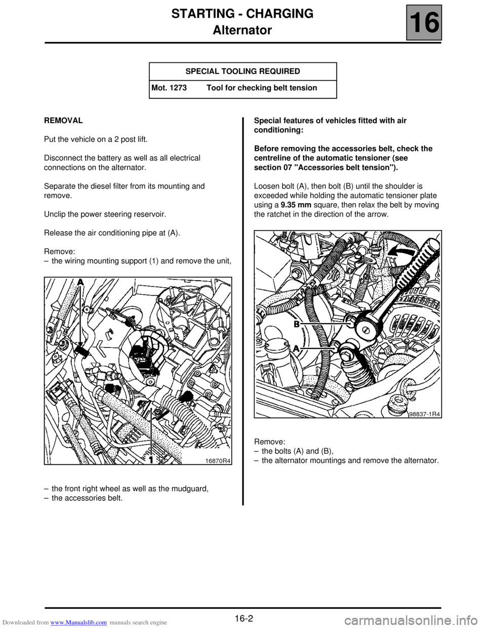
REMOVAL
Put the vehicle on a 2 post lift.
Disconnect the battery as well as all electrical
connections on the alternator.
Separate the diesel filter from its mounting and
remove.
Unclip the power steering reservoir.
Release the air conditioning pipe at (A).
Remove:
– the wiring mounting support (1) and remove the unit,
– the front right wheel as well as the mudguard,
– the accessories belt.Special features of vehicles fitted with air
conditioning:
Before removing the accessories belt, check the
centreline of the automatic tensioner (see
section 07 "Accessories belt tension").
Loosen bolt (A), then bolt (B) until the shoulder is
exceeded while holding the automatic tensioner plate
using a 9.35 mm square, then relax the belt by moving
the ratchet in the direction of the arrow.
Remove:
– the bolts (A) and (B),
– the alternator mountings and remove the alternator. SPECIAL TOOLING REQUIRED
Mot. 1273 Tool for checking belt tension
16870R4
98837-1R4
Page 102 of 118
Downloaded from www.Manualslib.com manuals search engine STARTING - CHARGING
Starter
16
16-5
REMOVAL
Put the vehicle on a 2 post lift.
Disconnect the battery.
Remove (for the Scénic):
– the front right hand grille as well as the mounting
bolts of the left hand grille,
– the closure panel of the scuttle,Remove (all types):
– the turbocharging air ducts between the exchanger
and the engine,
– the pre-catalytic converter mountings to the turbo.
Loosen the exhaust pipe clamp mounting.
Remove:
– the pre-catalytic converter stay (1),
– the catalytic converter mountings on the precatalytic
converter and remove this by moving the engine
towards the cooling system,
– the oil return pipe (8),
– the starter electrical connections.
– the starter mountings,
– the starter motor.
REFITTING
To remove, proceed in the reverse order.
Check the presence of the starter motor centring
dowel.
11020R
11036R2
16155R
Page 103 of 118
Downloaded from www.Manualslib.com manuals search engine COOLING SYSTEM
Filling and bleeding
19
119 COOLING SYSTEM
Filling and bleeding
There is no heater matrix water control valve.
Water flow is continuous in the heater matrix, which
contributes to the cooling of the engine.
FILLING
It is essential to open the bleed screw on the
cylinder head coolant pipe housing outlet.
Fill the circuit through the expansion bottle opening.
Close the bleed screw as soon as the fluid runs out in
a continuous jet.
Start the engine (2500 rpm).
Adjust the level by overflow for a period of about
4 minutes.
Tighten the expansion bottle cap.
BLEEDING
Let the engine run for 20 minutes at 2500 rpm, until
the engine cooling fan operates (time required for
automatic degassing).
Check the liquid level is at the "Maximum" marker.
DO NOT OPEN THE BLEED SCREW(S) WITH THE
ENGINE RUNNING.
REFIT THE EXPANSION BOTTLE CAP WHILE THE
ENGINE IS WARM.
19-1