2000 NISSAN PATROL rpm
[x] Cancel search: rpmPage 29 of 1033
TCM FUNCTION
The function of the TCM is to:
+Receive input signals sent from various switches and sensors.
+Determine required line pressure, shifting point, lock-up operation, and engine brake operation.
+Send required output signals to the respective solenoids.
INPUT/OUTPUT SIGNAL OF TCM
Sensors and solenoid valves Function
InputPNP switch Detects select lever position and sends a signal to TCM.
Accelerator position sensor Detects throttle valve position and sends a signal to TCM.
Accelerator position switch
(Off accel)Detects throttle valve's fully-closed position and sends a signal to TCM.
Accelerator position switch
(Full accel)Detects a throttle valve position of greater than 1/2 of full throttle and sends a
signal to TCM.
Engine speed signal From ECM.
A/T fluid temperature sensor Detects transmission fluid temperature and sends a signal to TCM.
Revolution sensor Detects output shaft rpm and sends a signal to TCM.
Vehicle speed sensorUsed as an auxiliary vehicle speed sensor. Sends a signal when revolution sen-
sor (installed on transmission) malfunctions.
Overdrive control switch
A/T mode switchSends a signal, which prohibits a shift to ªD
4º (overdrive) position, to the TCM.
OutputShift solenoid valve A/BSelects shifting point suited to driving conditions in relation to a signal sent from
TCM.
Line pressure solenoid valveRegulates (or decreases) line pressure suited to driving conditions in relation to
a signal sent from TCM.
Torque converter clutch solenoid valveRegulates (or decreases) lock-up pressure suited to driving conditions in relation
to a signal sent from TCM.
Overrun clutch solenoid valveControls an ªengine brakeº effect suited to driving conditions in relation to a sig-
nal sent from TCM.
O/D OFF indicator lamp
SPORT indicator lampShows TCM faults, when A/T control components malfunction.
OVERALL SYSTEM
Control System (Cont'd)
AT-1027
Page 30 of 1033
Self-diagnosis
After performing this procedure, place check marks for results on
the ªDIAGNOSTIC WORKSHEETº, AT-1038. Reference pages
are provided following the items.
SELF-DIAGNOSTIC PROCEDURE (With
CONSULT-II)
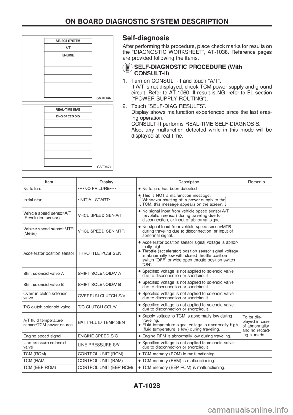
1. Turn on CONSULT-II and touch ªA/Tº.
If A/T is not displayed, check TCM power supply and ground
circuit. Refer to AT-1060. If result is NG, refer to EL section
(ªPOWER SUPPLY ROUTINGº).
2. Touch ªSELF-DIAG RESULTSº.
Display shows malfunction experienced since the last eras-
ing operation.
CONSULT-II performs REAL-TIME SELF-DIAGNOSIS.
Also, any malfunction detected while in this mode will be
displayed at real time.
Item Display Description Remarks
No failure
****NO FAILURE
****+No failure has been detected.
Initial start
*INITIAL START
*+This is NOT a malfunction message.
Whenever shutting off a power supply to the
TCM, this message appears on the screen.
[]
Vehicle speed sensorzA/T
(Revolution sensor)VHCL SPEED SENzA/T+No signal input from vehicle speed sensorzA/T
(revolution sensor) during traveling due to
disconnection, or input of abnormal signal.
Vehicle speed sensorzMTR
(Meter)VHCL SPEED SENzMTR+No signal input from vehicle speed sensorzMTR
during traveling due to disconnection, or input of
abnormal signal.
Accelerator position sensor THROTTLE POSI SEN+Accelerator position sensor signal voltage is abnor-
mally high.
+Throttle (accelerator) position sensor signal voltage
is abnormally low with closed throttle position
switch ªOFFº or wide open throttle position switch
ªONº.
Shift solenoid valve A SHIFT SOLENOID/V A+Specified voltage is not applied to solenoid valve
due to disconnection or shortcircuit.
Shift solenoid valve B SHIFT SOLENOID/V B+Specified voltage is not applied to solenoid valve
due to disconnection or shortcircuit.
Overrun clutch solenoid
valveOVERRUN CLUTCH S/V+Specified voltage is not applied to solenoid valve
due to disconnection or shortcircuit.
T/C clutch solenoid valve T/C CLUTCH SOL/V+Specified voltage is not applied to solenoid valve
due to disconnection or shortcircuit.
A/T fluid temperature
sensor/TCM power sourceBATT/FLUID TEMP SEN+Supply voltage to TCM is abnormally low during
traveling.
+Fluid temperature signal voltage is abnormally high
(fluid temperature is low) during traveling.To be dis-
played in case
of abnormality
and no record-
ing is made
Engine speed signal ENGINE SPEED SIG+Engine RPM is abnormally low during traveling.
Line pressure solenoid
valveLINE PRESSURE S/V+Specified voltage is not applied to solenoid valve
due to disconnection or shortcircuit.
TCM (ROM) CONTROL UNIT (ROM)+TCM memory (ROM) is malfunctioning.
TCM (RAM) CONTROL UNIT (RAM)+TCM memory (RAM) is malfunctioning.
TCM (EEP ROM) CONTROL UNIT (EEP ROM)+TCM memory (EEP ROM) is malfunctioning.
SAT014K
SAT987J
ON BOARD DIAGNOSTIC SYSTEM DESCRIPTION
AT-1028
Page 36 of 1033
Diagnosis by CONSULT-II
NOTICE
1.The CONSULT-II electrically displays shift timing and lock-up timing (that is, operation timing of each
solenoid).
Check for time difference between actual shift timing and the CONSULT-II display. If the difference is
noticeable, mechanical parts (except solenoids, sensors, etc.) may be malfunctioning. Check mechanical
parts using applicable diagnostic procedures.
2. Shift schedule (which implies gear position) displayed on CONSULT-II and that indicated in Service
Manual may differ slightly. This occurs because of the following reasons:
+Actual shift schedule has more or less tolerance or allowance,
+Shift schedule indicated in Service Manual refers to the point where shifts start. Gear position dis-
played on CONSULT-II indicates the point where shifts are completed.
3. Shift solenoid valve ªAº or ªBº is displayed on CONSULT-II at the start of shifting. Gear position is dis-
played upon completion of shifting (which is computed by TCM).
4. Additional CONSULT-II information can be found in the Operation Manual supplied with the CONSULT-II
unit.
SELF-DIAGNOSTIC RESULT TEST MODE
Refer to AT-1028.
DATA MONITOR DIAGNOSTIC TEST MODE
Item DisplayMonitor item
Description Remarks TCM
input
signalsMain
signals
Vehicle speed sensor 1 (A/T)
(Revolution sensor)VHCL/S SEzA/T
[km/h] or [mph]
XÐ+Vehicle speed computed from
signal of revolution sensor is
displayed.When racing engine in ªNº or ªPº
position with vehicle stationary,
CONSULT data may not indicate
0 km/h (0 MPH).
Vehicle speed sensor 2
(Meter)VHCL/S SEzMTR
[km/h] or [mph]
XÐ+Vehicle speed computed from
signal of vehicle speed sensor
is displayed.Vehicle speed display may not be
accurate under approx. 10 km/h
(6 MPH). It may not indicate 0
km/h (0 MPH) when vehicle is
stationary.
Accelerator position sensor THRTL POS SEN
[V]XÐ+Accelerator position sensor sig-
nal voltage is displayed.
A/T fluid temperature sensor FLUID TEMP SE
[V]
XÐ+A/T fluid temperature sensor
signal voltage is displayed.
+Signal voltage lowers as fluid
temperature rises.
Battery voltage BATTERY VOLT
[V]XÐ+Source voltage of TCM is dis-
played.
Engine speed ENGINE SPEED
[rpm]
XX+Engine speed, computed from
engine speed signal, is dis-
played.Engine speed display may not be
accurate under approx. 800 rpm.
It may not indicate 0 rpm even
when engine is not running.
Overdrive control switch OVERDRIVE SW
[ON/OFF] X Ð+ON/OFF state computed from
signal of overdrive control SW
is displayed.
P/N position switch PN POSI SW
[ON/OFF] X Ð+ON/OFF state computed from
signal of PN position SW is dis-
played.
R position switch R POSITION SW
[ON/OFF] X Ð+ON/OFF state computed from
signal of R position SW is dis-
played.
D position switch D POSITION SW
[ON/OFF] X Ð+ON/OFF state computed from
signal of D position SW is dis-
played.
2 position switch 2 POSITION SW
[ON/OFF] X Ð+ON/OFF status, computed from
signal of 2 position SW, is dis-
played.
ON BOARD DIAGNOSTIC SYSTEM DESCRIPTION
AT-1034
Page 43 of 1033
A/T Fluid Check
FLUID LEAKAGE CHECK
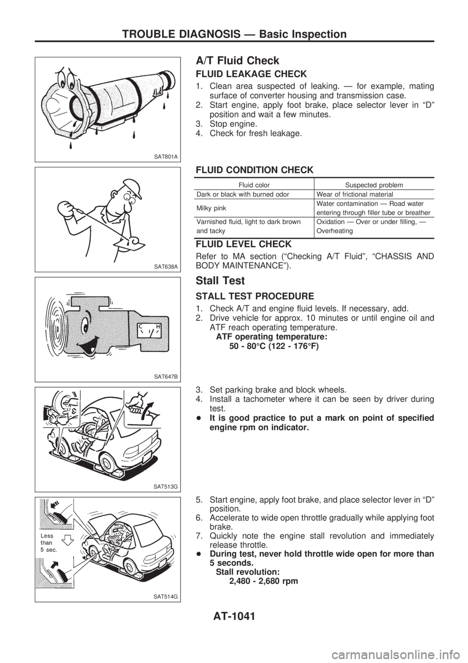
1. Clean area suspected of leaking. Ð for example, mating
surface of converter housing and transmission case.
2. Start engine, apply foot brake, place selector lever in ªDº
position and wait a few minutes.
3. Stop engine.
4. Check for fresh leakage.
FLUID CONDITION CHECK
Fluid color Suspected problem
Dark or black with burned odor Wear of frictional material
Milky pinkWater contamination Ð Road water
entering through filler tube or breather
Varnished fluid, light to dark brown
and tackyOxidation Ð Over or under filling, Ð
Overheating
FLUID LEVEL CHECK
Refer to MA section (ªChecking A/T Fluidº, ªCHASSIS AND
BODY MAINTENANCEº).
Stall Test
STALL TEST PROCEDURE
1. Check A/T and engine fluid levels. If necessary, add.
2. Drive vehicle for approx. 10 minutes or until engine oil and
ATF reach operating temperature.
ATF operating temperature:
50 - 80ÉC (122 - 176ÉF)
3. Set parking brake and block wheels.
4. Install a tachometer where it can be seen by driver during
test.
+It is good practice to put a mark on point of specified
engine rpm on indicator.
5. Start engine, apply foot brake, and place selector lever in ªDº
position.
6. Accelerate to wide open throttle gradually while applying foot
brake.
7. Quickly note the engine stall revolution and immediately
release throttle.
+During test, never hold throttle wide open for more than
5 seconds.
Stall revolution:
2,480 - 2,680 rpm
SAT801A
SAT638A
SAT647B
SAT513G
SAT514G
TROUBLE DIAGNOSIS Ð Basic Inspection
AT-1041
Page 81 of 1033
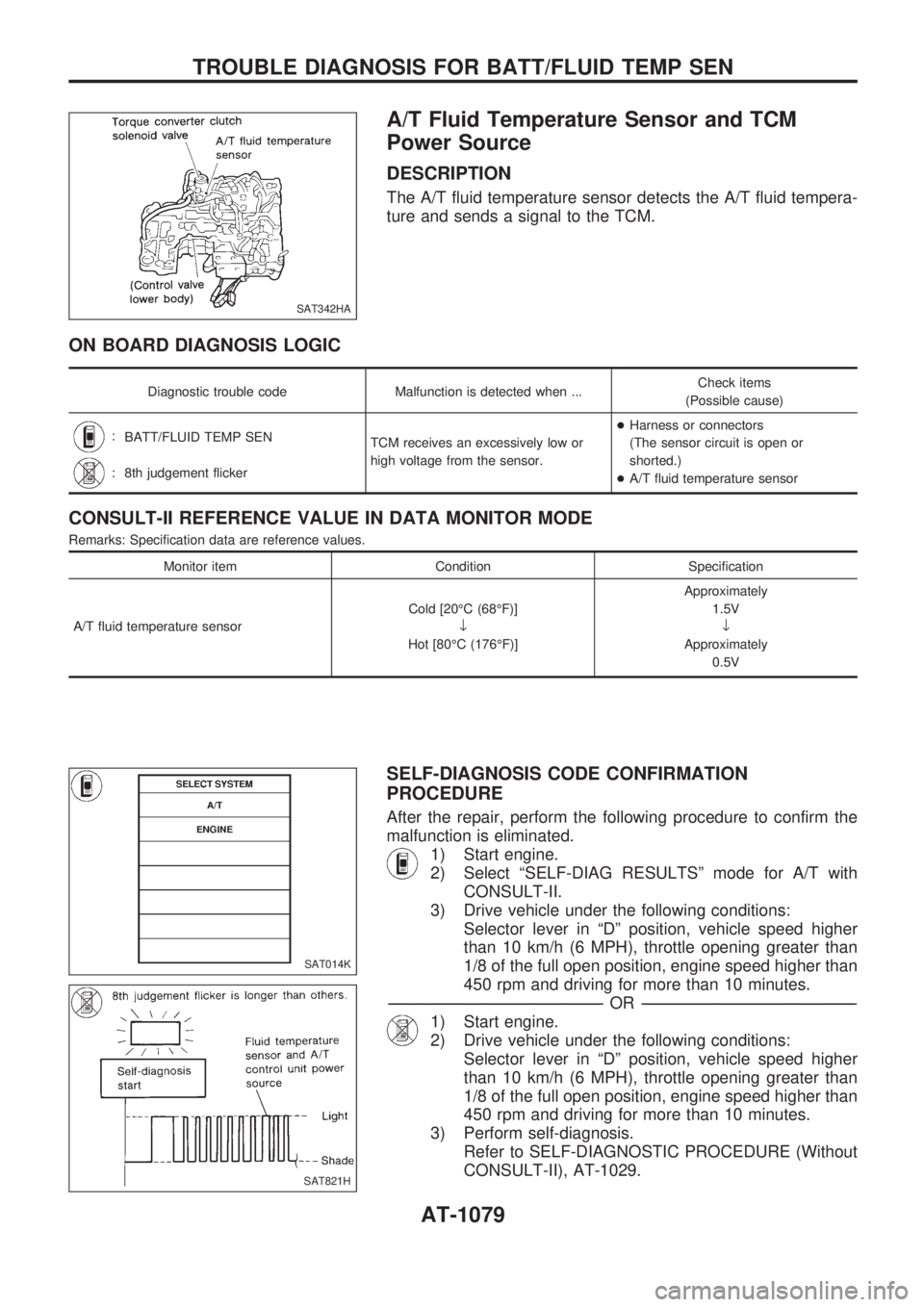
A/T Fluid Temperature Sensor and TCM
Power Source
DESCRIPTION
The A/T fluid temperature sensor detects the A/T fluid tempera-
ture and sends a signal to the TCM.
ON BOARD DIAGNOSIS LOGIC
Diagnostic trouble code Malfunction is detected when ...Check items
(Possible cause)
:
BATT/FLUID TEMP SEN
TCM receives an excessively low or
high voltage from the sensor.+Harness or connectors
(The sensor circuit is open or
shorted.)
+A/T fluid temperature sensor
: 8th judgement flicker
CONSULT-II REFERENCE VALUE IN DATA MONITOR MODE
Remarks: Specification data are reference values.
Monitor item Condition Specification
A/T fluid temperature sensorCold [20ÉC (68ÉF)]
¯
Hot [80ÉC (176ÉF)]Approximately
1.5V
¯
Approximately
0.5V
SELF-DIAGNOSIS CODE CONFIRMATION
PROCEDURE
After the repair, perform the following procedure to confirm the
malfunction is eliminated.
1) Start engine.
2) Select ªSELF-DIAG RESULTSº mode for A/T with
CONSULT-II.
3) Drive vehicle under the following conditions:
Selector lever in ªDº position, vehicle speed higher
than 10 km/h (6 MPH), throttle opening greater than
1/8 of the full open position, engine speed higher than
450 rpm and driving for more than 10 minutes.
-------------------------------------------------------------------------------------------------------------------------------------------------------------------------------------------------------------------------------------------------OR-------------------------------------------------------------------------------------------------------------------------------------------------------------------------------------------------------------------------------------------------
1) Start engine.
2) Drive vehicle under the following conditions:
Selector lever in ªDº position, vehicle speed higher
than 10 km/h (6 MPH), throttle opening greater than
1/8 of the full open position, engine speed higher than
450 rpm and driving for more than 10 minutes.
3) Perform self-diagnosis.
Refer to SELF-DIAGNOSTIC PROCEDURE (Without
CONSULT-II), AT-1029.
SAT342HA
SAT014K
SAT821H
TROUBLE DIAGNOSIS FOR BATT/FLUID TEMP SEN
AT-1079
Page 209 of 1033
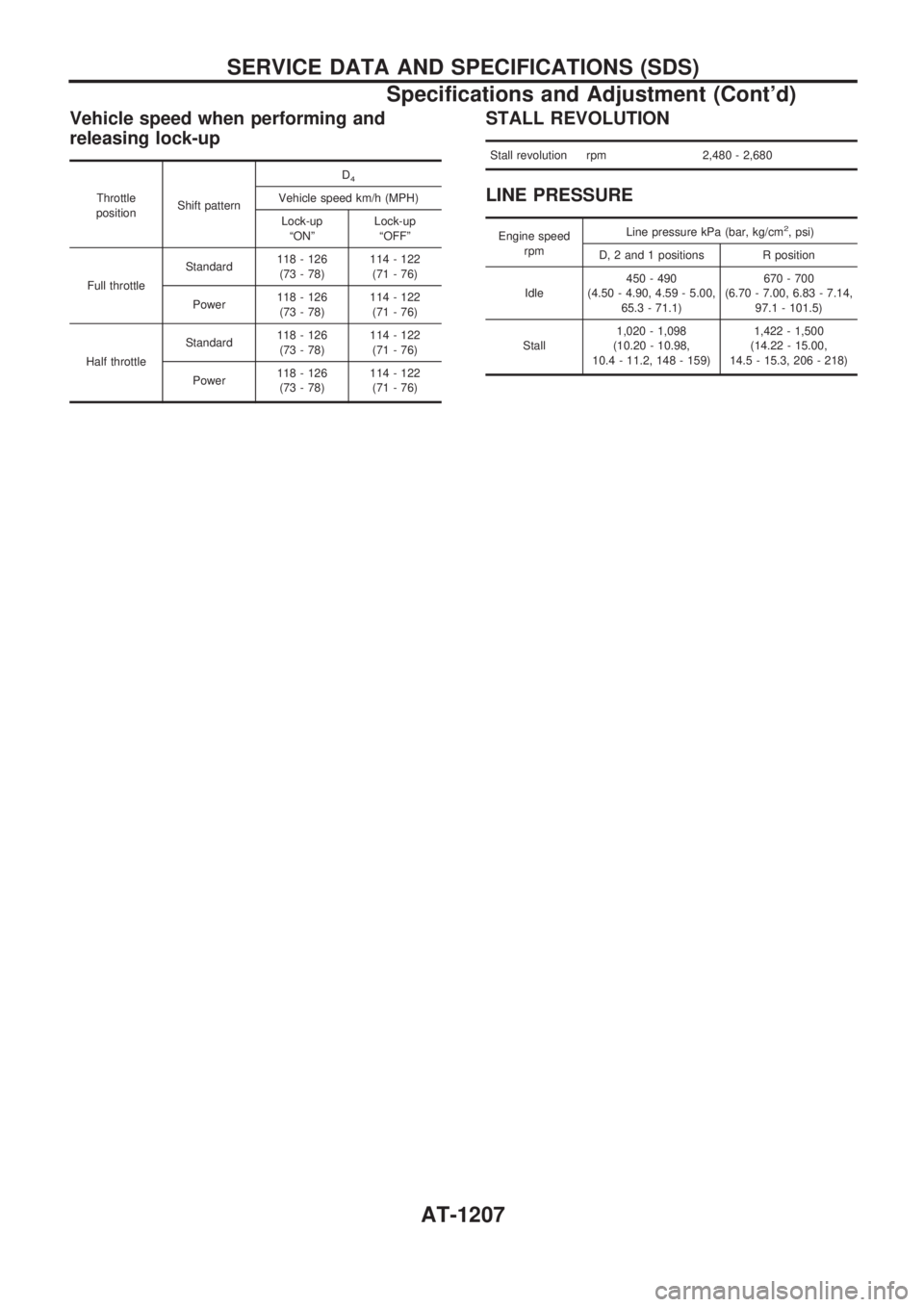
Vehicle speed when performing and
releasing lock-up
Throttle
positionShift patternD
4
Vehicle speed km/h (MPH)
Lock-up
ªONºLock-up
ªOFFº
Full throttleStandard118 - 126
(73 - 78)114 - 122
(71 - 76)
Power118 - 126
(73 - 78)114 - 122
(71 - 76)
Half throttleStandard118 - 126
(73 - 78)114 - 122
(71 - 76)
Power118 - 126
(73 - 78)114 - 122
(71 - 76)
STALL REVOLUTION
Stall revolution rpm 2,480 - 2,680
LINE PRESSURE
Engine speed
rpmLine pressure kPa (bar, kg/cm2, psi)
D, 2 and 1 positions R position
Idle450 - 490
(4.50 - 4.90, 4.59 - 5.00,
65.3 - 71.1)670 - 700
(6.70 - 7.00, 6.83 - 7.14,
97.1 - 101.5)
Stall1,020 - 1,098
(10.20 - 10.98,
10.4 - 11.2, 148 - 159)1,422 - 1,500
(14.22 - 15.00,
14.5 - 15.3, 206 - 218)
SERVICE DATA AND SPECIFICATIONS (SDS)
Specifications and Adjustment (Cont'd)
AT-1207
Page 254 of 1033
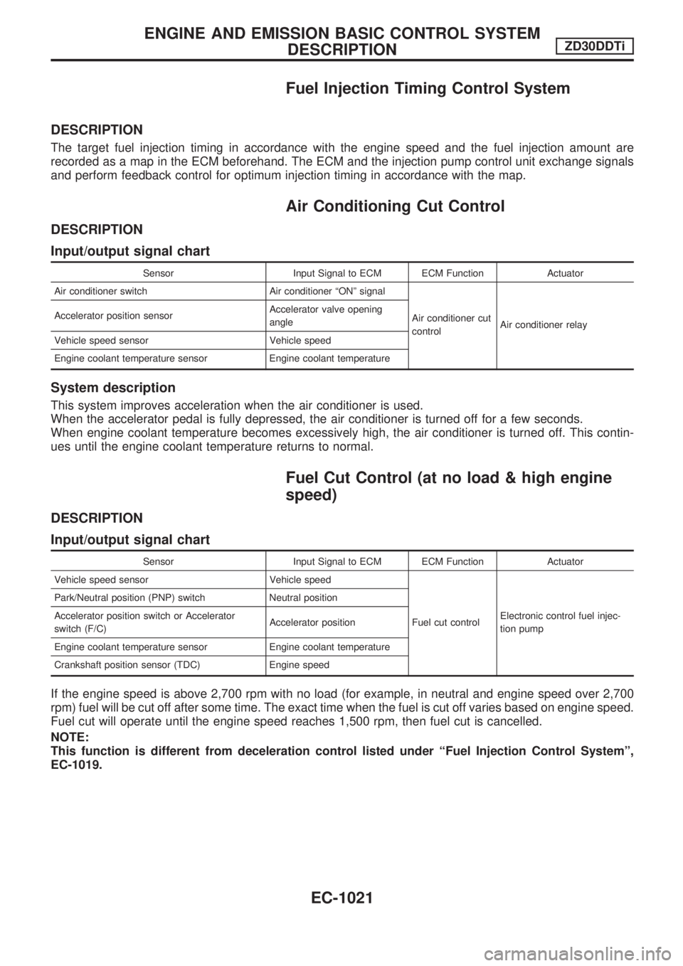
Fuel Injection Timing Control System
DESCRIPTION
The target fuel injection timing in accordance with the engine speed and the fuel injection amount are
recorded as a map in the ECM beforehand. The ECM and the injection pump control unit exchange signals
and perform feedback control for optimum injection timing in accordance with the map.
Air Conditioning Cut Control
DESCRIPTION
Input/output signal chart
Sensor Input Signal to ECM ECM Function Actuator
Air conditioner switch Air conditioner ªONº signal
Air conditioner cut
controlAir conditioner relay Accelerator position sensorAccelerator valve opening
angle
Vehicle speed sensor Vehicle speed
Engine coolant temperature sensor Engine coolant temperature
System description
This system improves acceleration when the air conditioner is used.
When the accelerator pedal is fully depressed, the air conditioner is turned off for a few seconds.
When engine coolant temperature becomes excessively high, the air conditioner is turned off. This contin-
ues until the engine coolant temperature returns to normal.
Fuel Cut Control (at no load & high engine
speed)
DESCRIPTION
Input/output signal chart
Sensor Input Signal to ECM ECM Function Actuator
Vehicle speed sensor Vehicle speed
Fuel cut controlElectronic control fuel injec-
tion pump Park/Neutral position (PNP) switch Neutral position
Accelerator position switch or Accelerator
switch (F/C)Accelerator position
Engine coolant temperature sensor Engine coolant temperature
Crankshaft position sensor (TDC) Engine speed
If the engine speed is above 2,700 rpm with no load (for example, in neutral and engine speed over 2,700
rpm) fuel will be cut off after some time. The exact time when the fuel is cut off varies based on engine speed.
Fuel cut will operate until the engine speed reaches 1,500 rpm, then fuel cut is cancelled.
NOTE:
This function is different from deceleration control listed under ªFuel Injection Control Systemº,
EC-1019.
ENGINE AND EMISSION BASIC CONTROL SYSTEM
DESCRIPTIONZD30DDTi
EC-1021
Page 272 of 1033
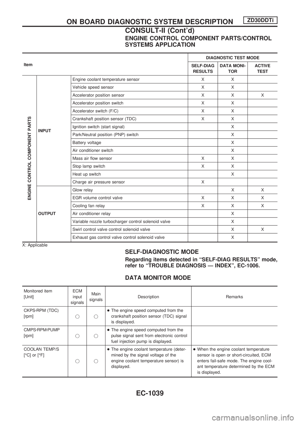
ENGINE CONTROL COMPONENT PARTS/CONTROL
SYSTEMS APPLICATION
ItemDIAGNOSTIC TEST MODE
SELF-DIAG
RESULTSDATA MONI-
TORACTIVE
TEST
ENGINE CONTROL COMPONENT PARTS
INPUTEngine coolant temperature sensor X X
Vehicle speed sensor X X
Accelerator position sensor X X X
Accelerator position switch X X
Accelerator switch (F/C) X X
Crankshaft position sensor (TDC) X X
Ignition switch (start signal) X
Park/Neutral position (PNP) switch X
Battery voltage X
Air conditioner switch X
Mass air flow sensor X X
Stop lamp switch X X
Heat up switch X
Charge air pressure sensor X
OUTPUTGlow relayXX
EGR volume control valve X X X
Cooling fan relay X X X
Air conditioner relay X
Variable nozzle turbocharger control solenoid valve X
Swirl control valve control solenoid valve X X
Exhaust gas control valve control solenoid valve X
X: Applicable
SELF-DIAGNOSTIC MODE
Regarding items detected in ªSELF-DIAG RESULTSº mode,
refer to ªTROUBLE DIAGNOSIS Ð INDEXº, EC-1006.
DATA MONITOR MODE
Monitored item
[Unit]ECM
input
signalsMain
signalsDescription Remarks
CKPSzRPM (TDC)
[rpm]jj+The engine speed computed from the
crankshaft position sensor (TDC) signal
is displayed.
CMPSzRPMzPUMP
[rpm]jj+The engine speed computed from the
pulse signal sent from electronic control
fuel injection pump is displayed.
COOLAN TEMP/S
[ÉC] or [ÉF]
jj+The engine coolant temperature (deter-
mined by the signal voltage of the
engine coolant temperature sensor) is
displayed.+When the engine coolant temperature
sensor is open or short-circuited, ECM
enters fail-safe mode. The engine cool-
ant temperature determined by the ECM
is displayed.
ON BOARD DIAGNOSTIC SYSTEM DESCRIPTIONZD30DDTi
CONSULT-II (Cont'd)
EC-1039