2000 NISSAN PATROL Electric
[x] Cancel search: ElectricPage 380 of 1033
2 CHECK BATTERY AND ALTERNATOR
Check that the proper type of battery and alternator is installed.
Refer to EL section (ªBATTERYº and ªCHARGING SYSTEMº).
OK or NG
OKcGO TO 5.
NGcReplace with a proper one.
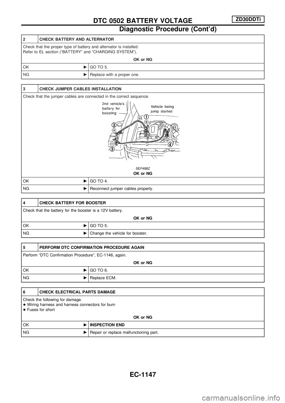
3 CHECK JUMPER CABLES INSTALLATION
Check that the jumper cables are connected in the correct sequence.
SEF488Z
OK or NG
OKcGO TO 4.
NGcReconnect jumper cables properly.
4 CHECK BATTERY FOR BOOSTER
Check that the battery for the booster is a 12V battery.
OK or NG
OKcGO TO 5.
NGcChange the vehicle for booster.
5 PERFORM DTC CONFIRMATION PROCEDURE AGAIN
Perform ªDTC Confirmation Procedureº, EC-1146, again.
OK or NG
OKcGO TO 6.
NGcReplace ECM.
6 CHECK ELECTRICAL PARTS DAMAGE
Check the following for damage.
+Wiring harness and harness connectors for burn
+Fuses for short
OK or NG
OKcINSPECTION END
NGcRepair or replace malfunctioning part.
DTC 0502 BATTERY VOLTAGEZD30DDTi
Diagnostic Procedure (Cont'd)
EC-1147
Page 440 of 1033
Description
SYSTEM DESCRIPTION
Sensor Input Signal to ECM ECM Function Actuator
Electronic controlled fuel injection pump Fuel injection signal
EGR volume control EGR volume control valve Crankshaft position sensor (TDC) Engine speed
Vehicle speed sensor Vehicle speed
Engine coolant temperature sensor Engine coolant temperature
Ignition switch Start signal
Throttle position sensor Throttle position
Battery Battery voltage
Mass air flow sensor Amount of intake air
Air conditioner switch Air conditioner operation
Electrical load Electrical load signal
PNP switch Park/Neutral position signal
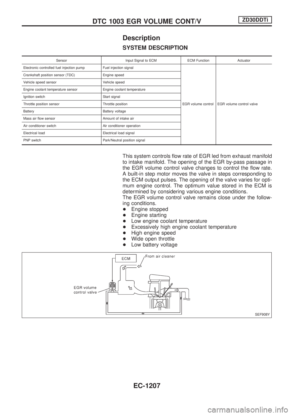
This system controls flow rate of EGR led from exhaust manifold
to intake manifold. The opening of the EGR by-pass passage in
the EGR volume control valve changes to control the flow rate.
A built-in step motor moves the valve in steps corresponding to
the ECM output pulses. The opening of the valve varies for opti-
mum engine control. The optimum value stored in the ECM is
determined by considering various engine conditions.
The EGR volume control valve remains close under the follow-
ing conditions.
+Engine stopped
+Engine starting
+Low engine coolant temperature
+Excessively high engine coolant temperature
+High engine speed
+Wide open throttle
+Low battery voltage
SEF908Y
DTC 1003 EGR VOLUME CONT/VZD30DDTi
EC-1207
Page 511 of 1033
ELECTRICAL SYSTEM
SECTION
EL
When you read wiring diagrams:
+Read GI section, ªHOW TO READ WIRING DIAGRAMSº.
When you perform trouble diagnoses, read GI section, ªHOW TO FOLLOW FLOW
CHART IN TROUBLE DIAGNOSESº and ªHOW TO PERFORM EFFICIENT DIAGNOSIS
FOR AN ELECTRICAL INCIDENTº.
+Check for any service bulletins before servicing the vehicle.
MODIFICATION NOTICE:
+Power window (driver's side only) with an interruption detection function has been adopted.
+ID code entry procedure of multi-remote control system has been changed.
+NATS (Nissan Anti-Theft System) has been adopted on ZD engine model.
CONTENTS
PRECAUTIONS AND PREPARATION............... 1003
Supplemental Restraint System (SRS) ªAIR
BAGº and ªSEAT BELT PRE-TENSIONERº ... 1003
POWER SUPPLY ROUTING............................... 1004
Schematic ........................................................ 1004
Wiring Diagram Ð POWER Ð ........................ 1005
GROUND DISTRIBUTION/LHD MODELS.......... 1013
Engine Room Harness..................................... 1013
Engine Control Harness................................... 1016
Main Harness ................................................... 1017
Body Harness .................................................. 1020
Body No. 2 Harness ........................................ 1022
Back Door and Rear Window Defogger
Harness ............................................................ 1023
GROUND DISTRIBUTION/RHD MODELS......... 1024
Engine Room Harness..................................... 1024
Engine Control Harness................................... 1027
Main Harness ................................................... 1028
Body Harness .................................................. 1031
Body No. 2 Harness ........................................ 1033
Back Door and Rear Window Defogger
Harness ............................................................ 1034
BATTERY............................................................. 1035
Service Data and Specifications (SDS) ........... 1035
STARTING SYSTEM........................................... 1036
Wiring Diagram Ð START Ð/M/T Models...... 1036
Wiring Diagram Ð START Ð/A/T Models ...... 1037
Construction ..................................................... 1038Service Data and Specifications (SDS) ........... 1039
CHARGING SYSTEM.......................................... 1040
Wiring Diagram Ð CHARGE ........................... 1040
Construction ..................................................... 1041
Service Data and Specifications (SDS) ........... 1041
COMBINATION SWITCH.................................... 1042
Check ............................................................... 1042
STEERING SWITCH............................................ 1043
Check ............................................................... 1043
HEADLAMP Ð Daytime Light System Ð........ 1044
Wiring Diagram Ð DTRL Ð ............................ 1044
PARKING, LICENSE AND TAIL LAMPS........... 1046
Wiring Diagram Ð TAIL/L Ð/LHD Models ...... 1046
Wiring Diagram Ð TAIL/L Ð/RHD Models ..... 1048
STOP LAMP........................................................ 1050
Wiring Diagram Ð STOP/L Ð......................... 1050
BACK-UP LAMP.................................................. 1051
Wiring Diagram Ð BACK/L Ð/RHD Models ... 1051
FRONT FOG LAMP............................................. 1052
Wiring Diagram Ð F/FOG Ð .......................... 1052
REAR FOG LAMP............................................... 1053
Wiring Diagram Ð R/FOG Ð .......................... 1053
CORNERING LAMP............................................ 1054
Wiring Diagram Ð CORNER Ð/LHD Models . 1054
System Description/RHD Models .................... 1055
Wiring Diagram Ð CORNER Ð/RHD Models1056
Trouble Diagnoses/RHD Models ..................... 1057
EL
Page 512 of 1033
TURN SIGNAL AND HAZARD WARNING
LAMPS................................................................. 1058
Wiring Diagram Ð TURN Ð ........................... 1058
ILLUMINATION .................................................... 1060
Schematic ........................................................ 1060
Wiring Diagram Ð ILL Ð ................................ 1061
INTERIOR ROOM LAMP ..................................... 1067
System Description .......................................... 1067
Wiring Diagram Ð ROOM/L Ð/LHD Models .. 1068
Wiring Diagram Ð ROOM/L Ð/RHD Models.. 1070
Trouble Diagnoses ........................................... 1072
METER AND GAUGES ....................................... 1073
Wiring Diagram Ð METER Ð/LHD Models .... 1073
Wiring Diagram Ð METER Ð/RHD Models ... 1075
WARNING LAMPS .............................................. 1078
Schematic ........................................................ 1078
Wiring Diagram Ð WARN Ð .......................... 1080
WARNING CHIME ............................................... 1091
System Description .......................................... 1091
Wiring Diagram Ð CHIME Ð/LHD Models ..... 1092
Wiring Diagram Ð CHIME Ð/RHD Models .... 1093
Trouble Diagnoses ........................................... 1094
Electrical Components Inspection ................... 1097
FRONT WIPER AND WASHER .......................... 1098
Wiring Diagram Ð WIPER Ð.......................... 1098
HEADLAMP WIPER AND WASHER .................. 1099
Wiring Diagram Ð HLC Ð .............................. 1099
HORN ................................................................... 1100
Wiring Diagram Ð HORN Ð ........................... 1100
REAR WINDOW DEFOGGER ............................. 1101
System Description .......................................... 1101
Wiring Diagram Ð DEF Ð/LHD Models ......... 1102
Wiring Diagram Ð DEF Ð/RHD Models......... 1104
Trouble Diagnoses ........................................... 1106
Electrical Components Inspection ................... 1107
AUDIO .................................................................. 1108
Wiring Diagram Ð REMOTE Ð ...................... 1108
AUDIO ANTENNA ............................................... 1109
Wiring Diagram Ð P/ANT Ð/RHD Models ..... 1109
AUTOMATIC SPEED CONTROL DEVICE
(ASCD) ................................................................. 1110
Schematic ........................................................ 1110
Wiring Diagram Ð ASCD Ð ........................... 1111
POWER WINDOW ............................................... 1115
System Description .......................................... 1115
Schematic ........................................................ 1116
Wiring Diagram Ð WINDOW Ð...................... 1117
Trouble Diagnoses ........................................... 1122
POWER DOOR LOCK Ð Super Lock Ð .......... 1124
Component Parts and Harness Connector
Location............................................................ 1124
System Description .......................................... 1125
Schematic ........................................................ 1127
Wiring Diagram Ð S/LOCK Ð/LHD Models ... 1128 Wiring Diagram Ð S/LOCK Ð/RHD Models... 1133
Trouble Diagnoses ........................................... 1138
MULTI-REMOTE CONTROL SYSTEM ............... 1149
System Description .......................................... 1149
Wiring Diagram Ð MULTI Ð/LHD Models...... 1150
Wiring Diagram Ð MULTI Ð/RHD Models ..... 1152
Trouble Diagnoses ........................................... 1154
ID Code Entry Procedure ................................ 1156
Remote Controller Battery Replacement ......... 1157
SUPER LOCK CONTROL UNIT ......................... 1159
Description ....................................................... 1159
Schematic ........................................................ 1160
Input/Output Operation Signal ......................... 1162
NATS (Nissan Anti-Theft System) .................... 1163
Component Parts and Harness Connector
Location............................................................ 1163
System Description .......................................... 1164
System Composition ........................................ 1165
Wiring Diagram Ð NATS Ð ............................ 1166
Wiring Diagram Ð NATS Ð/LHD Models ....... 1167
Wiring Diagram Ð NATS Ð/RHD Models ...... 1168
CONSULT-II ..................................................... 1169
Trouble Diagnoses ........................................... 1172
How to Replace NATS IMMU .......................... 1183
LOCATION OF ELECTRICAL UNITS ................. 1185
Engine Compartment ....................................... 1185
Passenger Compartment Ð LHD Models ....... 1186
Passenger Compartment Ð RHD Models ...... 1188
HARNESS LAYOUT ............................................ 1191
How to Read Harness Layout ......................... 1191
Main Harness/LHD Models .............................. 1192
Main Harness/RHD Models ............................. 1196
Engine Room Harness/LHD Models................ 1200
Engine Room Harness/RHD Models ............... 1204
Engine Harness ............................................... 1208
Engine Control Harness................................... 1209
Body Harness/LHD Models ............................. 1210
Body Harness/RHD Models ............................. 1214
Body No. 2 Harness/LHD Models ................... 1218
Body No. 2 Harness/RHD Models ................... 1220
Chassis Harness .............................................. 1222
Room Lamp Harness ....................................... 1223
Front Door Harness (Driver side) .................... 1224
Front Door Harness (Passenger side)............. 1225
Back Door Harness and Rear Window
Defogger Harness ............................................ 1226
WIRING DIAGRAM CODES (CELL CODES) ..... 1227
Wiring Diagram Codes (Cell Codes) ............... 1227
ELECTRICAL SYSTEM
Page 513 of 1033
Supplemental Restraint System (SRS) ªAIR
BAGº and ªSEAT BELT PRE-TENSIONERº
The Supplemental Restraint System such as ªAIR BAGº and ªSEAT BELT PRE-TENSIONERº used along
with a seat belt, helps to reduce the risk or severity of injury to the driver and front passenger for certain
types of collision. The SRS system composition which is available to NISSAN MODEL Y61 is as follows (The
composition varies according to the destination and optional equipment.):
+For a frontal collision
The Supplemental Restraint System consists of driver air bag module (located in the center of the
steering wheel), front passenger air bag module (located on the instrument panel on passenger side),
seat belt pre-tensioners, a diagnosis sensor unit, warning lamp, wiring harness and spiral cable.
+For a side collision
The Supplemental Restraint System consists of front side air bag module (located in the outer side of
front seat), satellite sensor, diagnosis sensor unit (one of components of air bags for a frontal collision),
wiring harness, warning lamp (one of components of air bags for a frontal collision).
Information necessary to service the system safely is included in theRS sectionof this Service Manual.
WARNING:
+To avoid rendering the SRS inoperative, which could increase the risk of personal injury or death
in the event of a collision which would result in air bag inflation, all maintenance should be per-
formed by an authorized NISSAN dealer.
+Improper maintenance, including incorrect removal and installation of the SRS, can lead to per-
sonal injury caused by unintentional activation of the system. For removal of Spiral Cable and
Air Bag Module, see the RS section.
+Do not use electrical test equipment on any circuit related to the SRS unless instructed to in this
Service Manual. Spiral cable and wiring harnesses covered with yellow insulation tape either just
before the harness connectors or for the complete harness are related to the SRS.
PRECAUTIONS AND PREPARATION
EL-1003
Page 605 of 1033
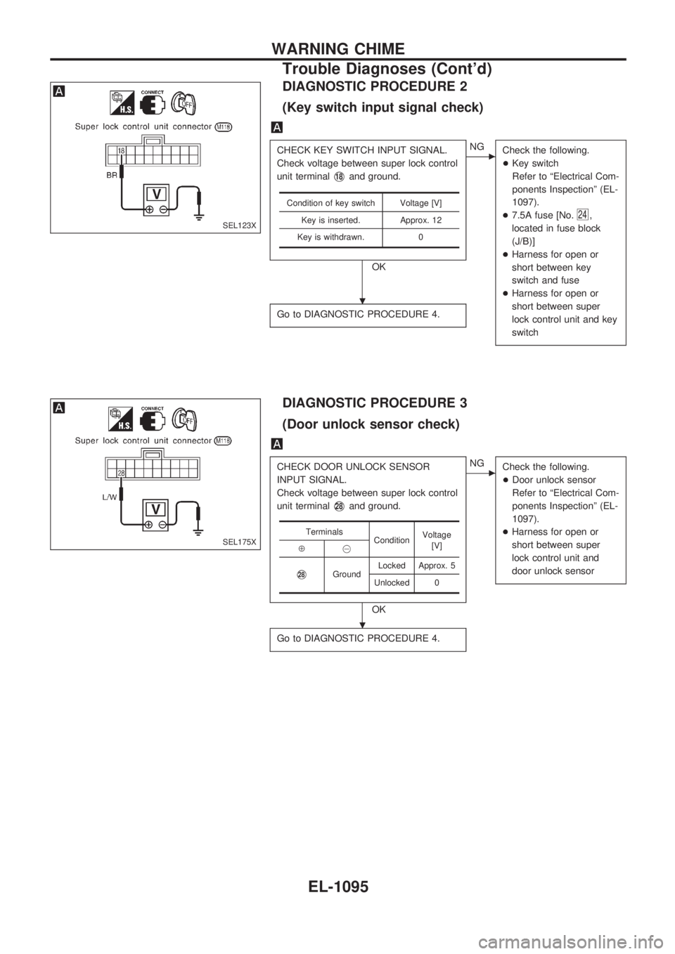
DIAGNOSTIC PROCEDURE 2
(Key switch input signal check)
CHECK KEY SWITCH INPUT SIGNAL.
Check voltage between super lock control
unit terminal
V18and ground.
OK
cNG
Check the following.
+Key switch
Refer to ªElectrical Com-
ponents Inspectionº (EL-
1097).
+7.5A fuse [No.
24,
located in fuse block
(J/B)]
+Harness for open or
short between key
switch and fuse
+Harness for open or
short between super
lock control unit and key
switch
Go to DIAGNOSTIC PROCEDURE 4.
Condition of key switch Voltage [V]
Key is inserted. Approx. 12
Key is withdrawn. 0
DIAGNOSTIC PROCEDURE 3
(Door unlock sensor check)
CHECK DOOR UNLOCK SENSOR
INPUT SIGNAL.
Check voltage between super lock control
unit terminal
V28and ground.
OK
cNG
Check the following.
+Door unlock sensor
Refer to ªElectrical Com-
ponents Inspectionº (EL-
1097).
+Harness for open or
short between super
lock control unit and
door unlock sensor
Go to DIAGNOSTIC PROCEDURE 4.
Terminals
ConditionVoltage
[V]
Å@
V28GroundLocked Approx. 5
Unlocked 0
SEL123X
SEL175X
.
.
WARNING CHIME
Trouble Diagnoses (Cont'd)
EL-1095
Page 606 of 1033
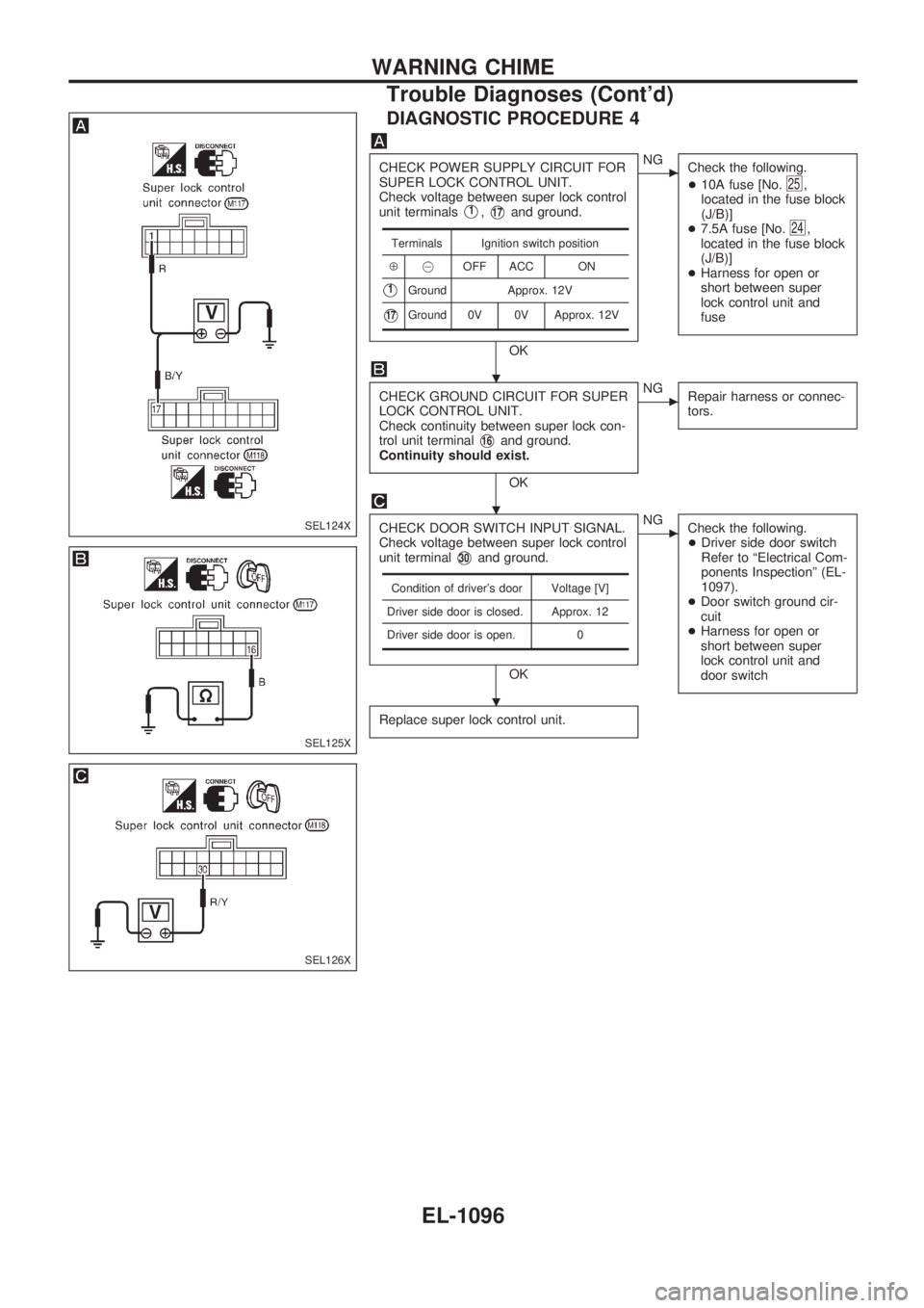
DIAGNOSTIC PROCEDURE 4
CHECK POWER SUPPLY CIRCUIT FOR
SUPER LOCK CONTROL UNIT.
Check voltage between super lock control
unit terminals
V1,V17and ground.
OK
cNG
Check the following.
+10A fuse [No.
25,
located in the fuse block
(J/B)]
+7.5A fuse [No.
24,
located in the fuse block
(J/B)]
+Harness for open or
short between super
lock control unit and
fuse
CHECK GROUND CIRCUIT FOR SUPER
LOCK CONTROL UNIT.
Check continuity between super lock con-
trol unit terminal
V16and ground.
Continuity should exist.
OK
cNG
Repair harness or connec-
tors.
CHECK DOOR SWITCH INPUT SIGNAL.
Check voltage between super lock control
unit terminal
V30and ground.
OK
cNG
Check the following.
+Driver side door switch
Refer to ªElectrical Com-
ponents Inspectionº (EL-
1097).
+Door switch ground cir-
cuit
+Harness for open or
short between super
lock control unit and
door switch
Replace super lock control unit.
Terminals Ignition switch position
Å@OFF ACC ON
V1Ground Approx. 12V
V17Ground 0V 0V Approx. 12V
Condition of driver's door Voltage [V]
Driver side door is closed. Approx. 12
Driver side door is open. 0
SEL124X
SEL125X
SEL126X
.
.
.
WARNING CHIME
Trouble Diagnoses (Cont'd)
EL-1096
Page 607 of 1033
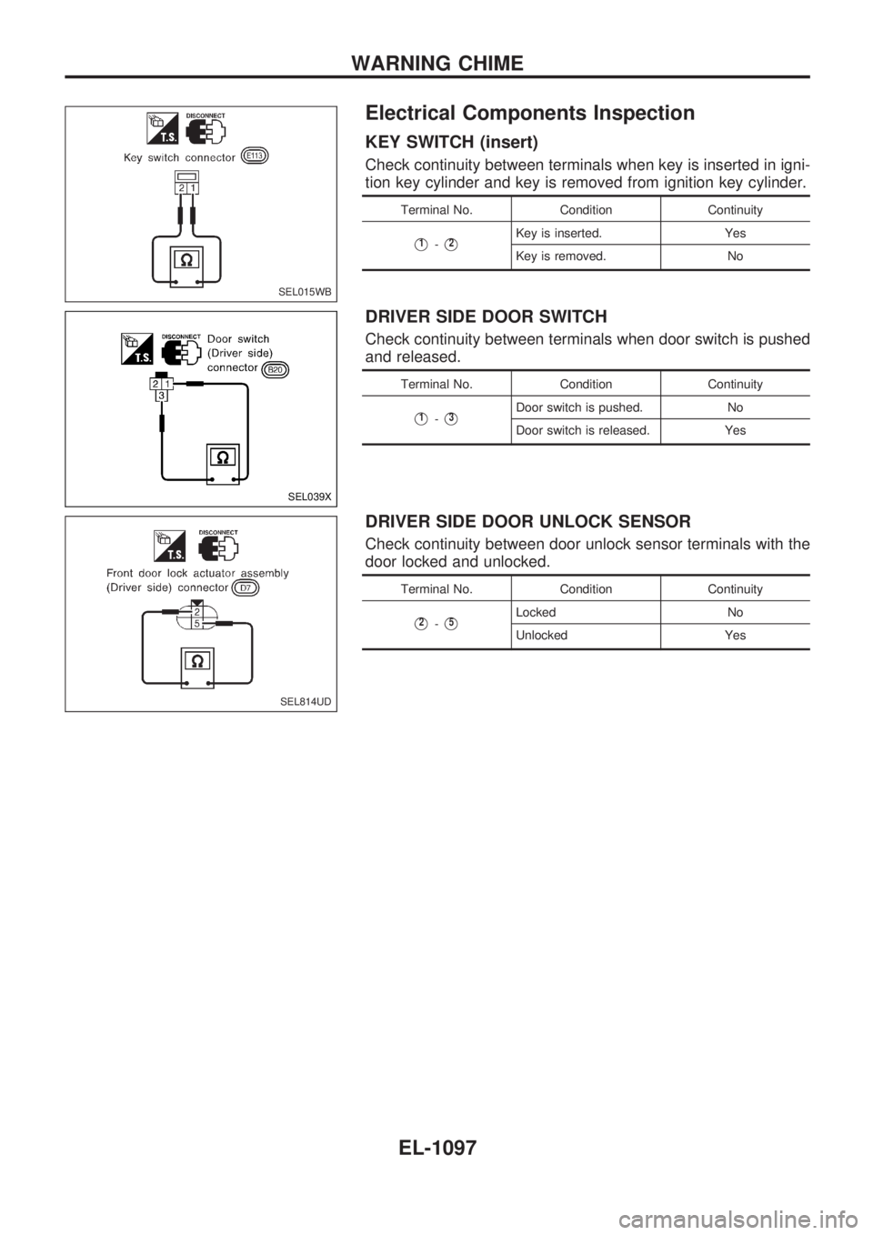
Electrical Components Inspection
KEY SWITCH (insert)
Check continuity between terminals when key is inserted in igni-
tion key cylinder and key is removed from ignition key cylinder.
Terminal No. Condition Continuity
V1-V2Key is inserted. Yes
Key is removed. No
DRIVER SIDE DOOR SWITCH
Check continuity between terminals when door switch is pushed
and released.
Terminal No. Condition Continuity
V1-V3Door switch is pushed. No
Door switch is released. Yes
DRIVER SIDE DOOR UNLOCK SENSOR
Check continuity between door unlock sensor terminals with the
door locked and unlocked.
Terminal No. Condition Continuity
V2-V5Locked No
Unlocked Yes
SEL015WB
SEL039X
SEL814UD
WARNING CHIME
EL-1097