2000 NISSAN PATROL instrument panel
[x] Cancel search: instrument panelPage 301 of 1033
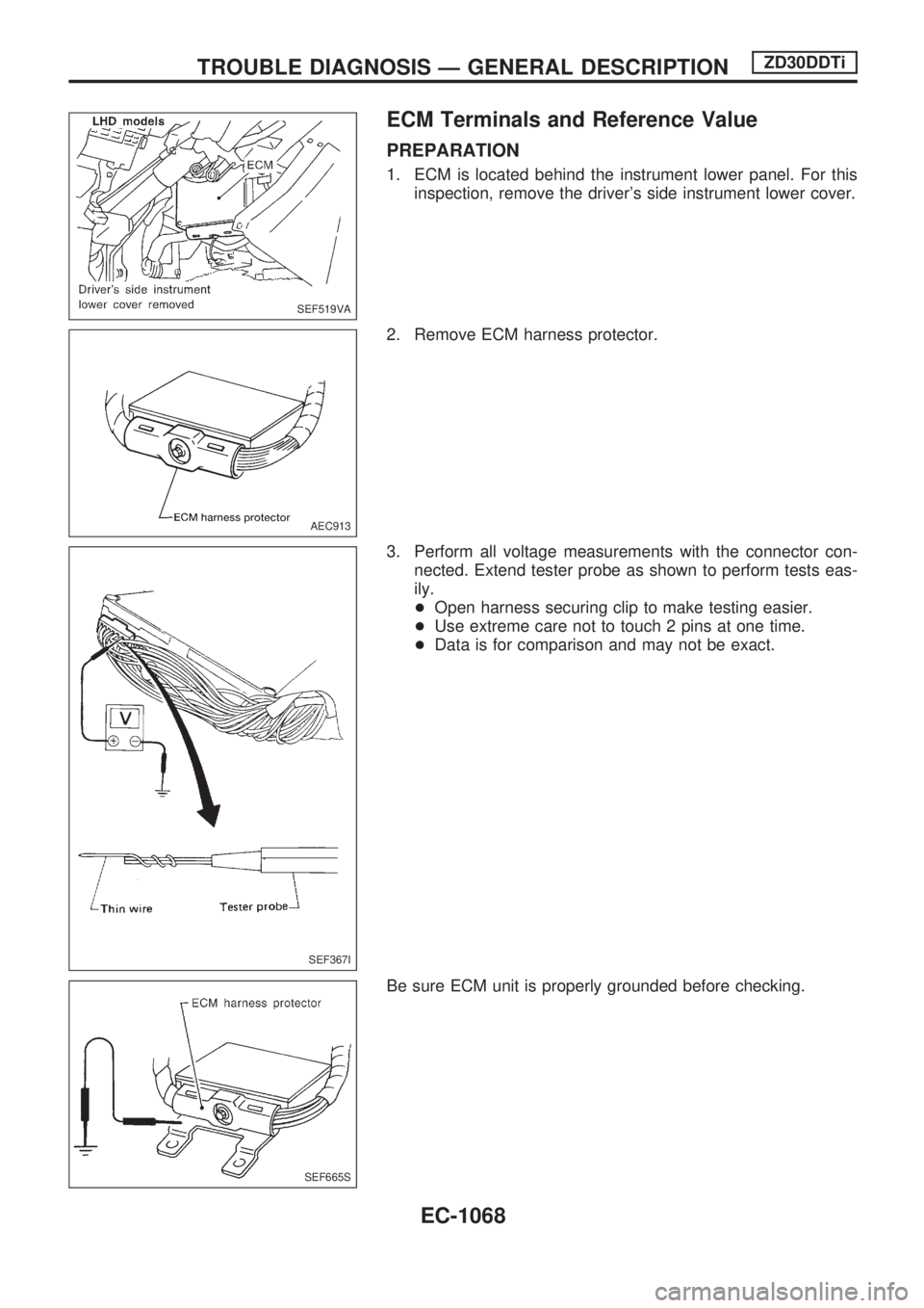
ECM Terminals and Reference Value
PREPARATION
1. ECM is located behind the instrument lower panel. For this
inspection, remove the driver's side instrument lower cover.
2. Remove ECM harness protector.
3. Perform all voltage measurements with the connector con-
nected. Extend tester probe as shown to perform tests eas-
ily.
+Open harness securing clip to make testing easier.
+Use extreme care not to touch 2 pins at one time.
+Data is for comparison and may not be exact.
Be sure ECM unit is properly grounded before checking.
SEF519VA
AEC913
SEF367I
SEF665S
TROUBLE DIAGNOSIS Ð GENERAL DESCRIPTIONZD30DDTi
EC-1068
Page 474 of 1033
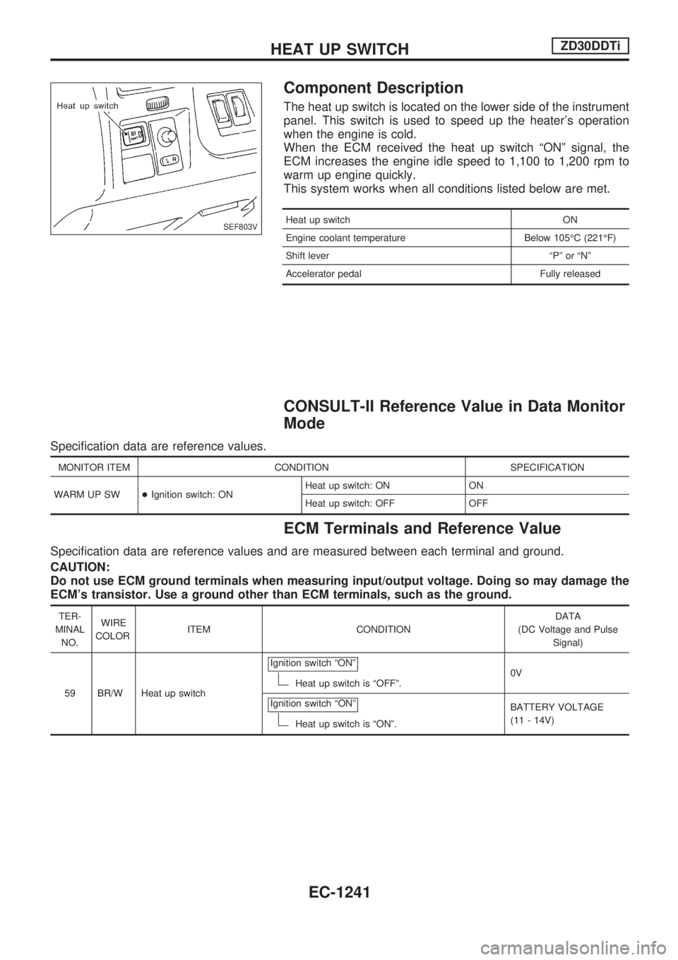
Component Description
The heat up switch is located on the lower side of the instrument
panel. This switch is used to speed up the heater's operation
when the engine is cold.
When the ECM received the heat up switch ªONº signal, the
ECM increases the engine idle speed to 1,100 to 1,200 rpm to
warm up engine quickly.
This system works when all conditions listed below are met.
Heat up switch ON
Engine coolant temperature Below 105ÉC (221ÉF)
Shift lever ªPº or ªNº
Accelerator pedal Fully released
CONSULT-II Reference Value in Data Monitor
Mode
Specification data are reference values.
MONITOR ITEM CONDITION SPECIFICATION
WARM UP SW+Ignition switch: ONHeat up switch: ON ON
Heat up switch: OFF OFF
ECM Terminals and Reference Value
Specification data are reference values and are measured between each terminal and ground.
CAUTION:
Do not use ECM ground terminals when measuring input/output voltage. Doing so may damage the
ECM's transistor. Use a ground other than ECM terminals, such as the ground.
TER-
MINAL
NO.WIRE
COLORITEM CONDITIONDATA
(DC Voltage and Pulse
Signal)
59 BR/W Heat up switchIgnition switch ªONº
Heat up switch is ªOFFº.0V
Ignition switch ªONº
Heat up switch is ªONº.BATTERY VOLTAGE
(11 - 14V)
SEF803V
HEAT UP SWITCHZD30DDTi
EC-1241
Page 513 of 1033
Supplemental Restraint System (SRS) ªAIR
BAGº and ªSEAT BELT PRE-TENSIONERº
The Supplemental Restraint System such as ªAIR BAGº and ªSEAT BELT PRE-TENSIONERº used along
with a seat belt, helps to reduce the risk or severity of injury to the driver and front passenger for certain
types of collision. The SRS system composition which is available to NISSAN MODEL Y61 is as follows (The
composition varies according to the destination and optional equipment.):
+For a frontal collision
The Supplemental Restraint System consists of driver air bag module (located in the center of the
steering wheel), front passenger air bag module (located on the instrument panel on passenger side),
seat belt pre-tensioners, a diagnosis sensor unit, warning lamp, wiring harness and spiral cable.
+For a side collision
The Supplemental Restraint System consists of front side air bag module (located in the outer side of
front seat), satellite sensor, diagnosis sensor unit (one of components of air bags for a frontal collision),
wiring harness, warning lamp (one of components of air bags for a frontal collision).
Information necessary to service the system safely is included in theRS sectionof this Service Manual.
WARNING:
+To avoid rendering the SRS inoperative, which could increase the risk of personal injury or death
in the event of a collision which would result in air bag inflation, all maintenance should be per-
formed by an authorized NISSAN dealer.
+Improper maintenance, including incorrect removal and installation of the SRS, can lead to per-
sonal injury caused by unintentional activation of the system. For removal of Spiral Cable and
Air Bag Module, see the RS section.
+Do not use electrical test equipment on any circuit related to the SRS unless instructed to in this
Service Manual. Spiral cable and wiring harnesses covered with yellow insulation tape either just
before the harness connectors or for the complete harness are related to the SRS.
PRECAUTIONS AND PREPARATION
EL-1003
Page 847 of 1033
Supplemental Restraint System (SRS) ªAIR
BAGº and ªSEAT BELT PRE-TENSIONERº
The Supplemental Restraint System such as ªAIR BAGº and ªSEAT BELT PRE-TENSIONERº used along
with a seat belt, helps to reduce the risk or severity of injury to the driver and front passenger for certain
types of collision. The SRS system composition which is available to NISSAN MODEL Y61 is as follows (The
composition varies according to the destination and optional equipment.):
+For a frontal collision
The Supplemental Restraint System consists of driver air bag module (located in the center of the
steering wheel), front passenger air bag module (located on the instrument panel on passenger side),
seat belt pre-tensioners, a diagnosis sensor unit, warning lamp, wiring harness and spiral cable.
+For a side collision
The Supplemental Restraint System consists of front side air bag module (located in the outer side of
front seat), satellite sensor, diagnosis sensor unit (one of components of air bags for a frontal collision),
wiring harness, warning lamp (one of components of air bags for a frontal collision).
Information necessary to service the system safely is included in theRS sectionof this Service Manual.
WARNING:
+To avoid rendering the SRS inoperative, which could increase the risk of personal injury or death
in the event of a collision which would result in air bag inflation, all maintenance should be per-
formed by an authorized NISSAN dealer.
+Improper maintenance, including incorrect removal and installation of the SRS, can lead to per-
sonal injury caused by unintentional activation of the system. For removal of Spiral Cable and
Air Bag Module, see the RS section.
+Do not use electrical test equipment on any circuit related to the SRS unless instructed to in this
Service Manual. Spiral cable and wiring harnesses covered with yellow insulation tape either just
before the harness connectors or for the complete harness are related to the SRS.
Precautions for Fuel
DIESEL ENGINE*:
Diesel fuel of at least 50 cetane for ZD30DDTi engine
* If two types of diesel fuel are available, use summer or win-
ter fuel properly according to the following temperature con-
ditions.
+Above þ7ÉC (20ÉF) ... Summer type diesel fuel.
+Below þ7ÉC (20ÉF) ... Winter type diesel fuel.
CAUTION:
+Do not use home heating oil, gasoline, or other alternate
fuels in your diesel engine. The use of those can cause
engine damage.
+Do not use summer fuel at temperature below þ7ÉC
(20ÉF). The cold temperature will cause wax to form in
the fuel. As a result, it may prevent the engine from run-
ning smoothly.
+Do not add gasoline or other alternate fuels to diesel
fuel.
PRECAUTIONS AND PREPARATION
GI-1002
Page 857 of 1033
Supplemental Restraint System (SRS) ªAIR
BAGº and ªSEAT BELT PRE-TENSIONERº
The Supplemental Restraint System such as ªAIR BAGº and ªSEAT BELT PRE-TENSIONERº used along
with a seat belt, helps to reduce the risk or severity of injury to the driver and front passenger for certain
types of collision. The SRS system composition which is available to NISSAN MODEL Y61 is as follows (The
composition varies according to the destination and optional equipment.):
+For a frontal collision
The Supplemental Restraint System consists of driver air bag module (located in the center of the
steering wheel), front passenger air bag module (located on the instrument panel on passenger side),
seat belt pre-tensioners, a diagnosis sensor unit, warning lamp, wiring harness and spiral cable.
+For a side collision
The Supplemental Restraint System consists of front side air bag module (located in the outer side of
front seat), satellite sensor, diagnosis sensor unit (one of components of air bags for a frontal collision),
wiring harness, warning lamp (one of components of air bags for a frontal collision).
Information necessary to service the system safely is included in theRS sectionof this Service Manual.
WARNING:
+To avoid rendering the SRS inoperative, which could increase the risk of personal injury or death
in the event of a collision which would result in air bag inflation, all maintenance should be per-
formed by an authorized NISSAN dealer.
+Improper maintenance, including incorrect removal and installation of the SRS, can lead to per-
sonal injury caused by unintentional activation of the system. For removal of Spiral Cable and
Air Bag Module, see the RS section.
+Do not use electrical test equipment on any circuit related to the SRS unless instructed to in this
Service Manual. Spiral cable and wiring harnesses covered with yellow insulation tape either just
before the harness connectors or for the complete harness are related to the SRS.
Precautions for Refrigerant Connection
A new type refrigerant connection has been introduced to all refrigerant lines except the following location.
+Expansion valve to cooling unit
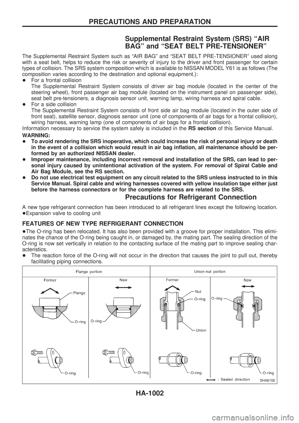
FEATURES OF NEW TYPE REFRIGERANT CONNECTION
+The O-ring has been relocated. It has also been provided with a groove for proper installation. This elimi-
nates the chance of the O-ring being caught in, or damaged by, the mating part. The sealing direction of the
O-ring is now set vertically in relation to the contacting surface of the mating part to improve sealing char-
acteristics.
+The reaction force of the O-ring will not occur in the direction that causes the joint to pull out, thereby
facilitating piping connections.
SHA815E
PRECAUTIONS AND PREPARATION
HA-1002
Page 974 of 1033
Supplemental Restraint System (SRS) ªAIR
BAGº and ªSEAT BELT PRE-TENSIONERº
The Supplemental Restraint System such as ªAIR BAGº and ªSEAT BELT PRE-TENSIONERº used along
with a seat belt, helps to reduce the risk or severity of injury to the driver and front passenger for certain
types of collision. The SRS composition which is available to NISSAN MODEL Y61 is as follows (The com-
position varies according to the destination and optional equipment.):
+For a frontal collision
The Supplemental Restraint System consists of driver air bag module (located in the center of the
steering wheel), front passenger air bag module (located on the instrument panel on passenger side),
seat belt pre-tensioners, a diagnosis sensor unit, warning lamp, wiring harness and spiral cable.
+For a side collision
The Supplemental Restraint System consists of front side air bag module (located in the outer side of
front seat), satellite sensor, diagnosis sensor unit (one of components of air bags for a frontal collision),
wiring harness, warning lamp (one of components of air bags for a frontal collision).
WARNING:
+To avoid rendering the SRS inoperative, which could increase the risk of personal injury or death
in the event of a collision which would result in air bag inflation, all maintenance should be per-
formed by an authorized NISSAN dealer.
+Improper maintenance, including incorrect removal and installation of the SRS, can lead to per-
sonal injury caused by unintentional activation of the system.
+Do not use electrical test equipment on any circuit related to the SRS unless instructed to in this
Service Manual. Spiral cable and wiring harnesses covered with yellow insulation tape either just
before the harness connectors or for the complete harness are related to the SRS.
PRECAUTION
RS-1002
Page 975 of 1033
Precautions for SRS ªAIR BAGº and ªSEAT
BELT PRE-TENSIONERº Service
+Do not use electrical test equipment to check SRS circuits unless instructed to in this Service Manual.
+Before servicing the SRS, turn ignition switch ªOFFº, disconnect both battery cables and wait at least 3
minutes.
For approximately 3 minutes after the cables are removed, it is still possible for the air bag and seat belt pre-
tensioner to deploy. Therefore, do not work on any SRS connectors or wires until at least 3 minutes have passed.
+Diagnosis sensor unit must always be installed with their arrow marks ªSº pointing towards the front of
the vehicle for proper operation. Also check diagnosis sensor unit for cracks, deformities or rust before
installation and replace as required.
+The spiral cable must be aligned with the neutral position since its rotations are limited. Do not attempt
to turn steering wheel or column after removal of steering gear.
+Handle air bag module carefully. Always place driver and passenger air bag modules with the pad side
facing upward and front side air bag modules (built-in type) with the stud bolt side facing down.
+Conduct self-diagnosis to check entire SRS for proper function after replacing any components.
+After air bag inflates, the front instrument panel assembly should be replaced if damaged.
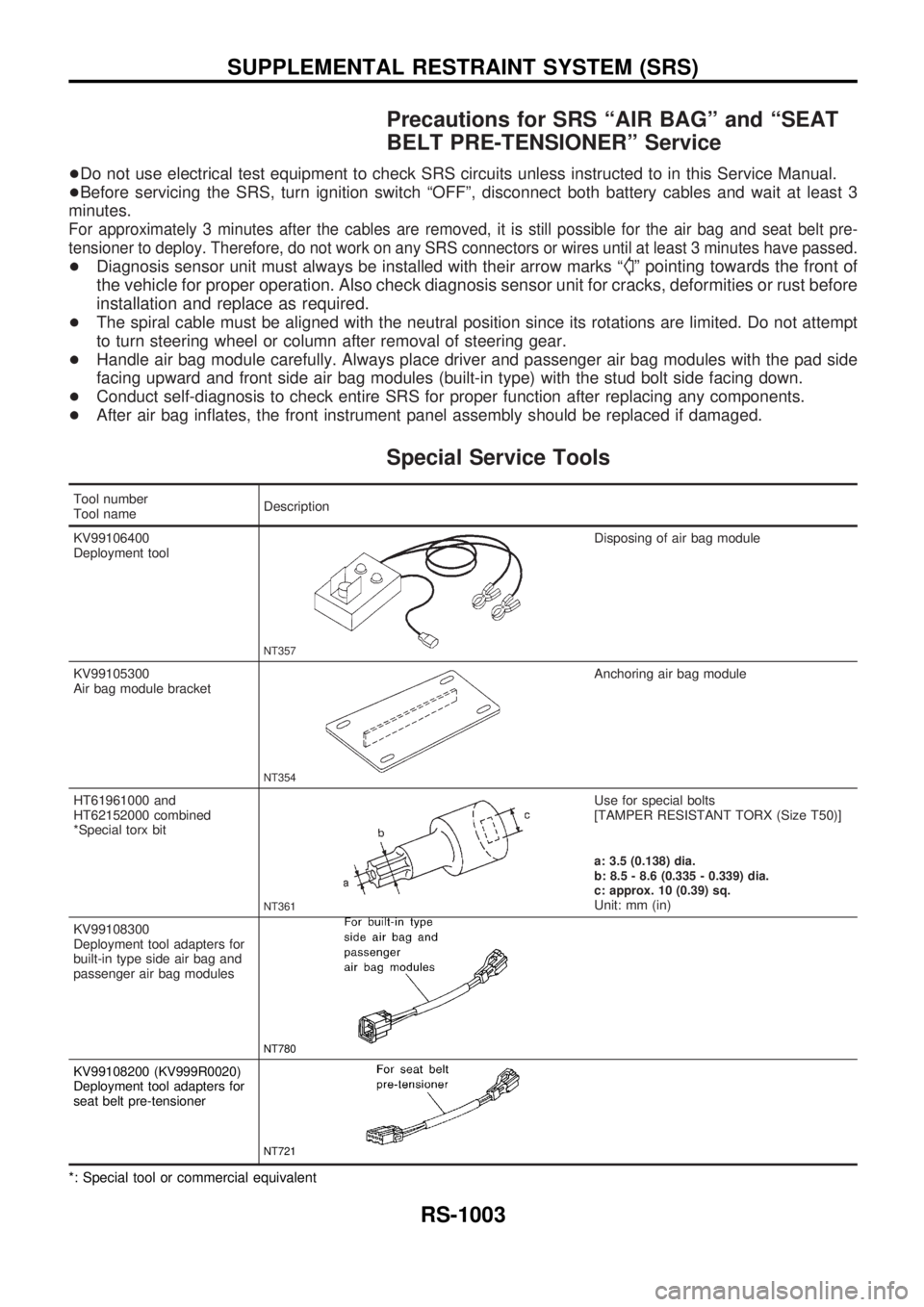
Special Service Tools
Tool number
Tool nameDescription
KV99106400
Deployment tool
NT357
Disposing of air bag module
KV99105300
Air bag module bracket
NT354
Anchoring air bag module
HT61961000 and
HT62152000 combined
*Special torx bit
NT361
Use for special bolts
[TAMPER RESISTANT TORX (Size T50)]
a: 3.5 (0.138) dia.
b: 8.5 - 8.6 (0.335 - 0.339) dia.
c: approx. 10 (0.39) sq.
Unit: mm (in)
KV99108300
Deployment tool adapters for
built-in type side air bag and
passenger air bag modules
NT780
KV99108200 (KV999R0020)
Deployment tool adapters for
seat belt pre-tensioner
NT721
*: Special tool or commercial equivalent
SUPPLEMENTAL RESTRAINT SYSTEM (SRS)
RS-1003
Page 978 of 1033
Maintenance Items
CAUTION:
Do not use electrical test equipment to check SRS circuit.
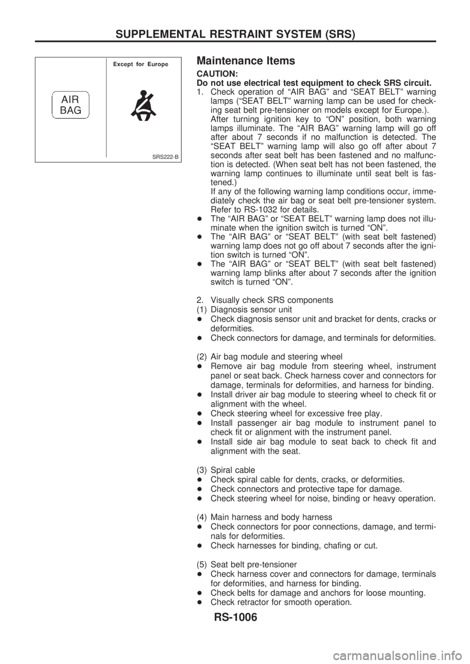
1. Check operation of ªAIR BAGº and ªSEAT BELTº warning
lamps (ªSEAT BELTº warning lamp can be used for check-
ing seat belt pre-tensioner on models except for Europe.).
After turning ignition key to ªONº position, both warning
lamps illuminate. The ªAIR BAGº warning lamp will go off
after about 7 seconds if no malfunction is detected. The
ªSEAT BELTº warning lamp will also go off after about 7
seconds after seat belt has been fastened and no malfunc-
tion is detected. (When seat belt has not been fastened, the
warning lamp continues to illuminate until seat belt is fas-
tened.)
If any of the following warning lamp conditions occur, imme-
diately check the air bag or seat belt pre-tensioner system.
Refer to RS-1032 for details.
+The ªAIR BAGº or ªSEAT BELTº warning lamp does not illu-
minate when the ignition switch is turned ªONº.
+The ªAIR BAGº or ªSEAT BELTº (with seat belt fastened)
warning lamp does not go off about 7 seconds after the igni-
tion switch is turned ªONº.
+The ªAIR BAGº or ªSEAT BELTº (with seat belt fastened)
warning lamp blinks after about 7 seconds after the ignition
switch is turned ªONº.
2. Visually check SRS components
(1) Diagnosis sensor unit
+Check diagnosis sensor unit and bracket for dents, cracks or
deformities.
+Check connectors for damage, and terminals for deformities.
(2) Air bag module and steering wheel
+Remove air bag module from steering wheel, instrument
panel or seat back. Check harness cover and connectors for
damage, terminals for deformities, and harness for binding.
+Install driver air bag module to steering wheel to check fit or
alignment with the wheel.
+Check steering wheel for excessive free play.
+Install passenger air bag module to instrument panel to
check fit or alignment with the instrument panel.
+Install side air bag module to seat back to check fit and
alignment with the seat.
(3) Spiral cable
+Check spiral cable for dents, cracks, or deformities.
+Check connectors and protective tape for damage.
+Check steering wheel for noise, binding or heavy operation.
(4) Main harness and body harness
+Check connectors for poor connections, damage, and termi-
nals for deformities.
+Check harnesses for binding, chafing or cut.
(5) Seat belt pre-tensioner
+Check harness cover and connectors for damage, terminals
for deformities, and harness for binding.
+Check belts for damage and anchors for loose mounting.
+Check retractor for smooth operation.
SRS222-B
SUPPLEMENTAL RESTRAINT SYSTEM (SRS)
RS-1006