2000 MITSUBISHI MONTERO egr valve
[x] Cancel search: egr valvePage 524 of 1839

DIESEL FUEL <4M4> -Troubleshooting13C-33
Item
No.Reference
page Code No.
or inspec-
tion proce-
dure No. Value to be
determined
as normal Inspection conditions Check item
06Vehicle
speed sen-
sorWhen drivingCompare the engine
speed displayed in the
speed meter with that
in MUT-IIMatchedCode No.
1713C-12
07Engine
speed sen-Engine: CrankingCompare the engine
speed displayed in theMatchedCode No.
1813C-13
sor (backup)Engine: Idlingtachometer with that in
MUT-II
08Engine
speed sen-Engine: CrankingCompare the engine
speed displayed in theMatchedCode No.
2113C-14
sorEngine: Idlingtachometer with that in
MUT-II
09Accelerator
pedal posi-Ignition switch: ONAccelerator pedal:
Idling position0.9 - 1.1VCode No.
1113C-8
tion sensor
(main)Accelerator pedal:
Fully opened position4.1 V or high-
er
10Idle switchIgnition switch: ONRelease the foot from
the accelerator pedal.0-1VCode No.
2313C-15
Step on the accelera-
tor pedal slightly4V or higher
11System volt-
ageIgnition switch: ONSystem volt-
ageProcedure
No. 1913C-31
13Timing con-Engine: After warmingIdling0%*1Code No.13C-16
trol valve*1up the engine2,500 r/min35 - 45%*125 or No.13C-20
High idling20 - 30%*143
14EGR com-
mand valueEngine: Idling0 - 100%*2–-
mand value
Engine: After warming up the engine
17Control
sleeve posi-Engine: After warming
up the engineIdling1.535 -
1.735 VCode No.
2613C-17
tion (target
value)2,500 r/minSlightly de-
creased.
High idling1.884 -
2.084 V
18Actual injec-Engine: After warmingIdling0.65 - 0.85 V––
tion timingup the engine2,500 r/min2.325 -
2.525 V
High idling3.814 -
4.014 V
19InjectionEngine: After warmingIdling0.3 - 0.5 V––
timing com-
mand valueup the engine2,500 r/min2.325 -
2.525 V
High idling3.814 -
4.014 V
www.WorkshopManuals.co.uk
Purchased from www.WorkshopManuals.co.uk
Page 525 of 1839

DIESEL FUEL <4M4> -Troubleshooting13C-34
Item
No.Reference
page Code No.
or inspec-
tion proce-
dure No. Value to be
determined
as normal Inspection conditions Check item
21GE actuatorEngine: After warmingIdling20 - 30%Code No.13C-17
up the engine2,500 r/min20 - 30%26 or No.13C-21
High idling20 - 29%48
22EGR dutyEngine: Idling0 - 100%*2––
valueEngine: After warming up the engine
23Control
sleeve posi-Engine: After warming
up the engineIdling1.535 -
1.735 VCode No.
2613C-17
tion (actual
value)2, 500 r/minSlightly de-
creased.
High idling1.884 -
2.084 V
24Accelerator
pedal posi-Ignition switch: ONAccelerator pedal:
Idling position0.9 - 1.1 VCode No.
2713C-18
tion sensor
(sub)Accelerator pedal:
Fully opened position4.1V or
higher
25Accelerator
pedal posi-Ignition switch: ONAccelerator pedal:
Idling position0%Code No.
2713C-18
tion sensor
(sub)Accelerator pedal:
Fully opened position99 - 100%
NOTE
*1: The opening degree of the timing control valve is converted into percentage. (0%: timer non-advanced angle,
100%: timer maximum advanced angle)
*
2: The opening degree of the EGR solenoid valve is converted into percentage.
Item
No.
Check itemInspection conditionsValue to be
determined
as normalCode No.
or inspec-
tion proce-
dure No.Reference
page
41Idle switchIgnition switch: ON
(check by repeatedRelease the foot from
the accelerator pedal.ON––
accelerator operation)Step on the accelerator
pedal slightly.OFF
43A/C switchEngine: Idling (The
A/C compressorA/C switch: ONON––
should be in operation
when the A/C switch is
“ON”)A/C switch: OFFOFF
44IgnitionIgnition switch: ONEngine: StopOFF––
switch-STEngine: CrankingON
45Ignition
switch-IGIgnition switch: ONON––
46Control
relayIgnition switch: ONON––
47A/C relayEngine: Idling after
warming up the engineA/C switch: OFFOFF (A/C
compressor
clutch not in
operation)––
A/C switch: ONON (A/C
compressor
clutch in op-
eration)
www.WorkshopManuals.co.uk
Purchased from www.WorkshopManuals.co.uk
Page 527 of 1839

DIESEL FUEL <4M4> -Troubleshooting13C-36
Item
No.Reference
page Code No.
or inspec-
tion proce-
dure No. Value to be
determined
as normal Inspection conditions Check item
58NeutralIgnition switch: ONN, P rangeN, P––
switchNone of the aboveD, R
60Fuel cut
relayIgnition switch: ON®OFF afterwards for a
certain period of timeON––
None of the aboveOFF
61EGR controlTurning off EGR quicklyON––
solenoid
valve No. 2None of the aboveOFF
62AT/MTIgnition switch: ONVehicles with A/TA/T––
switchVehicles with M/TM/T
68A/C switch 2A/C: Under high load or low loadON––
A/C: OFF or under medium loadOFF
69Warm up
switchDWarm up switch: ON
DHeater temperature setting: Maximum
DEngine coolant temperature: 90_C or lower
DBlower fan: ONON––
None of the aboveOFF
70PTC heaterDWarm up switch: ON
DHeater temperature setting: Maximum
DEngine coolant temperature: 65_Cto75_C
or lower
DBlower fan: ONON––
None of the aboveOFF
71PowerPower steering switch: ONON––
steering
switchPower steering switch: OFFOFF
www.WorkshopManuals.co.uk
Purchased from www.WorkshopManuals.co.uk
Page 529 of 1839

DIESEL FUEL <4M4> -Troubleshooting13C-38
Item
No.Reference
page Code No.
or inspec-
tion proce-
dure No. Value to be determined
as normal Inspection
conditions Drive Con-
tents Check item
25GE actuatorTurn the GE
actuator to
ONDIgnition
switch: ON
DEngine
speed:
0 r/min orMakes an audible
soundCode
No.4813C-21
26Turn the GE
actuator to
OFF
0 r/min or
lower
DControl
sleeve posi-
tion sensor:
Normal
27Fuel cut solenoid
valveTurn the
solenoid
valve to ONDIgnition
switch: ON
DVehicle
speed:
0 km/hMakes an audible
sound––
28EGR solenoid
valve No.1Turn the
solenoid
valve to ONDIgnition
switch: ON
DVehicleMakes an audible
sound––
29Turn the
solenoid
valve to ONspeed:
0 km/h
30EGR solenoid
valve No.2Turn the
solenoid
valve from
OFF to ON or
from ON to
OFFDIgnition
switch: ON
DVehicle
speed:
0 km/hMakes an audible
sound––
33PTC heaterSwitch the
PTC heater
relay ON/
OFF.DIgnition
switch: ONVoltage on the ECU
terminal No.9: 0 - 1V––
34Middle position
of GE actuatorHold the
injection
governor in
its middle
position.DIgnition
switch: ONWhen the crankshaft
is turned clockwise
during the adjustment
of the injection timing,
the injection pipes
spray out fuel.Code
No.4813C-21
www.WorkshopManuals.co.uk
Purchased from www.WorkshopManuals.co.uk
Page 557 of 1839

DIESEL FUEL <4M4> -General/Service Specifications/Troubleshooting13C-2
GENERAL
OUTLINE OF CHANGES
Some service procedures have been established as the following changes have been made due to the
compliance with the Emission Regulation StepIII.
DThe intake manifold cover and injection pump cover have been reshaped.
DThe throttle body assembly has been changed.
DThe EGR valve assembly has been changed.
SERVICE SPECIFICATIONS
ItemStandard value
Throttle body assembly resistanceΩat - 10 - 50_C12 - 20
at 50 - 100_C12 - 23
TROUBLESHOOTING
FAIL-SAFE, BACKUP FUNCTIONS
When abnormalities in the major sensors are detected by diagnosis functions, pre-set control logic operates
to maintain a safe driving condition for the vehicle.
Diagnosis itemControl features in malfunction
Accelerator pedal position sensorDAccelerator pedal released (idle switch ON)
Acceleration opening degree = 0 %
DAccelerator pedal applied (idle switch OFF)
Engine controlled at low speed
Acceleration opening degree = 40 %
DVoid cruise control
Idle switchDVoid idling speed control
DVoid cruise control
Engine speed sensorDEngine controlled at low speed
DVoid cruise control
Boost air temperature sensorMaintain the intake air temperature at 50_C
Vehicle speed sensorDVoid idling speed control
DVoid cruise control
DWith accelerator pedal released (when idle switch is on)
Accelerator opening angle = 0 %
DWith accelerator pedal depressed (when idle switch is off)
Accelerator opening angle = Fixed at 40 % (M/T), 28 % (A/T)
Engine coolant temperature sensorMaintain the engine coolant temperature at 80_C (engine running), 0_C
(engine stopped or just started)
Control sleeve position sensorDWith accelerator pedal released (when idle switch is on)
Engine speed = 800 r/min
DWith accelerator pedal depressed (when idle switch is off)
Engine speed = 2,000 r/min
DVoid cruise control
Timer piston position sensorDOpen control by means of engine speed
DVoid cruise control
Barometric pressure sensor (ECU built-in)Keep the barometric pressure at 101 kPa
www.WorkshopManuals.co.uk
Purchased from www.WorkshopManuals.co.uk
Page 558 of 1839

DIESEL FUEL <4M4> -Troubleshooting13C-3
Diagnosis item Control features in malfunction
Fuel temperature sensorMaintain the fuel temperature at 90_C
Boost pressure sensorDKeep the boost pressure as barometric pressure (101 kPa)
DVoid cruise control
Injection correction ROMDWhen backup data is normal: Correction calculation using backup
data
DWhen backup data is corrupted: Fixed at correction value±0%
GE actuatorDWith accelerator pedal released (when idle switch is on)
Engine speed = 800 r/min
DWith accelerator pedal depressed (when idle switch is off)
Engine speed = 2,000 r/min
DVoid cruise control
Over boostVoid cruise control
Timing control valveDOpen control by means of engine speed
DVoid cruise control
Throttle body assemblyVoid cruise control
EGR sensorEGR control is prohibited
EGR motorEGR control is prohibited
INSPECTION CHART FOR DIAGNOSIS CODES
Code No.Diagnosis itemReference page
11Accelerator pedal position sensor system13C-4
12Boost pressure sensor (boost sensor) system13C-4
13Barometric pressure sensor system13C-4
18Engine speed sensor (backup) system13C-4
21Engine speed sensor system13C-5
23Idle switch (accelerator pedal position sensor built-in) system13C-5
27Accelerator pedal position sensor (sub) system13C-5
41Throttle valve system13C-6
46Injection correction ROM system13C-6
48GE actuator (in the middle of control sleeve position sensor inoperative) system13C-7
51EGR valve system13C-8
www.WorkshopManuals.co.uk
Purchased from www.WorkshopManuals.co.uk
Page 563 of 1839

DIESEL FUEL <4M4> -Troubleshooting13C-8
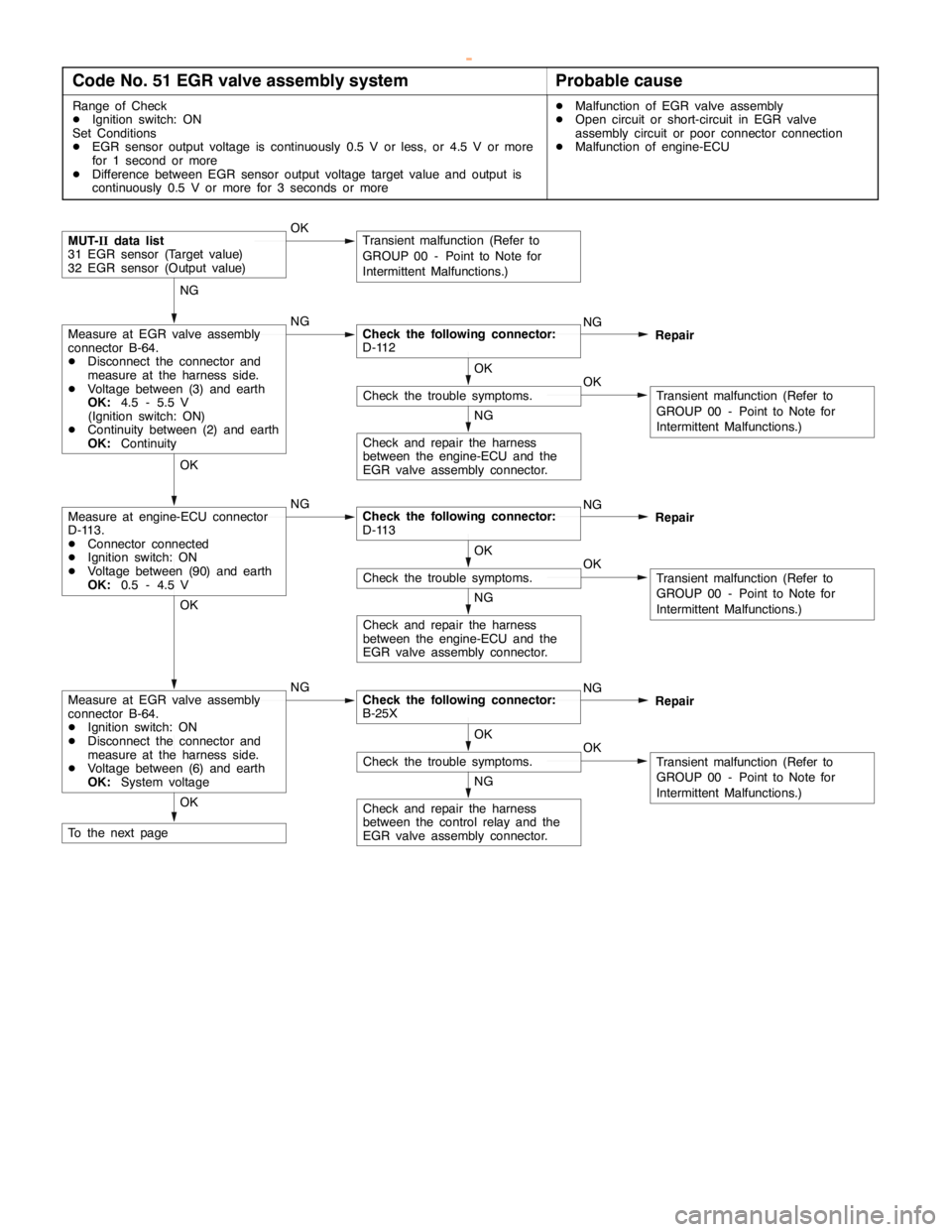
Code No. 51 EGR valve assembly systemProbable cause
Range of Check
DIgnition switch: ON
Set Conditions
DEGR sensor output voltage is continuously 0.5 V or less, or 4.5 V or more
for 1 second or more
DDifference between EGR sensor output voltage target value and output is
continuously 0.5 V or more for 3 seconds or moreDMalfunction of EGR valve assembly
DOpen circuit or short-circuit in EGR valve
assembly circuit or poor connector connection
DMalfunction of engine-ECU
Check and repair the harness
between the engine-ECU and the
EGR valve assembly connector.
NG
OKCheck the trouble symptoms.
OK
Transient malfunction (Refer to
GROUP 00 - Point to Note for
Intermittent Malfunctions.)
NGMeasure at engine-ECU connector
D-113.
DConnector connected
DIgnition switch: ON
DVoltage between (90) and earth
OK:0.5 - 4.5 VCheck the following connector:
D-113NG
Repair OK
Check and repair the harness
between the engine-ECU and the
EGR valve assembly connector.
NG
OKCheck the trouble symptoms.
OK
Transient malfunction (Refer to
GROUP 00 - Point to Note for
Intermittent Malfunctions.)
OKMUT-IIdata list
31 EGR sensor (Target value)
32 EGR sensor (Output value)Transient malfunction (Refer to
GROUP 00 - Point to Note for
Intermittent Malfunctions.)
NGMeasure at EGR valve assembly
connector B-64.
DDisconnect the connector and
measure at the harness side.
DVoltage between (3) and earth
OK:4.5 - 5.5 V
(Ignition switch: ON)
DContinuity between (2) and earth
OK:ContinuityCheck the following connector:
D-112NG
Repair NG
To the next pageOK
Check and repair the harness
between the control relay and the
EGR valve assembly connector.
NG
OKCheck the trouble symptoms.
OK
Transient malfunction (Refer to
GROUP 00 - Point to Note for
Intermittent Malfunctions.)
NGMeasure at EGR valve assembly
connector B-64.
DIgnition switch: ON
DDisconnect the connector and
measure at the harness side.
DVoltage between (6) and earth
OK:System voltageCheck the following connector:
B-25XNG
Repair OK
www.WorkshopManuals.co.uk
Purchased from www.WorkshopManuals.co.uk
Page 564 of 1839

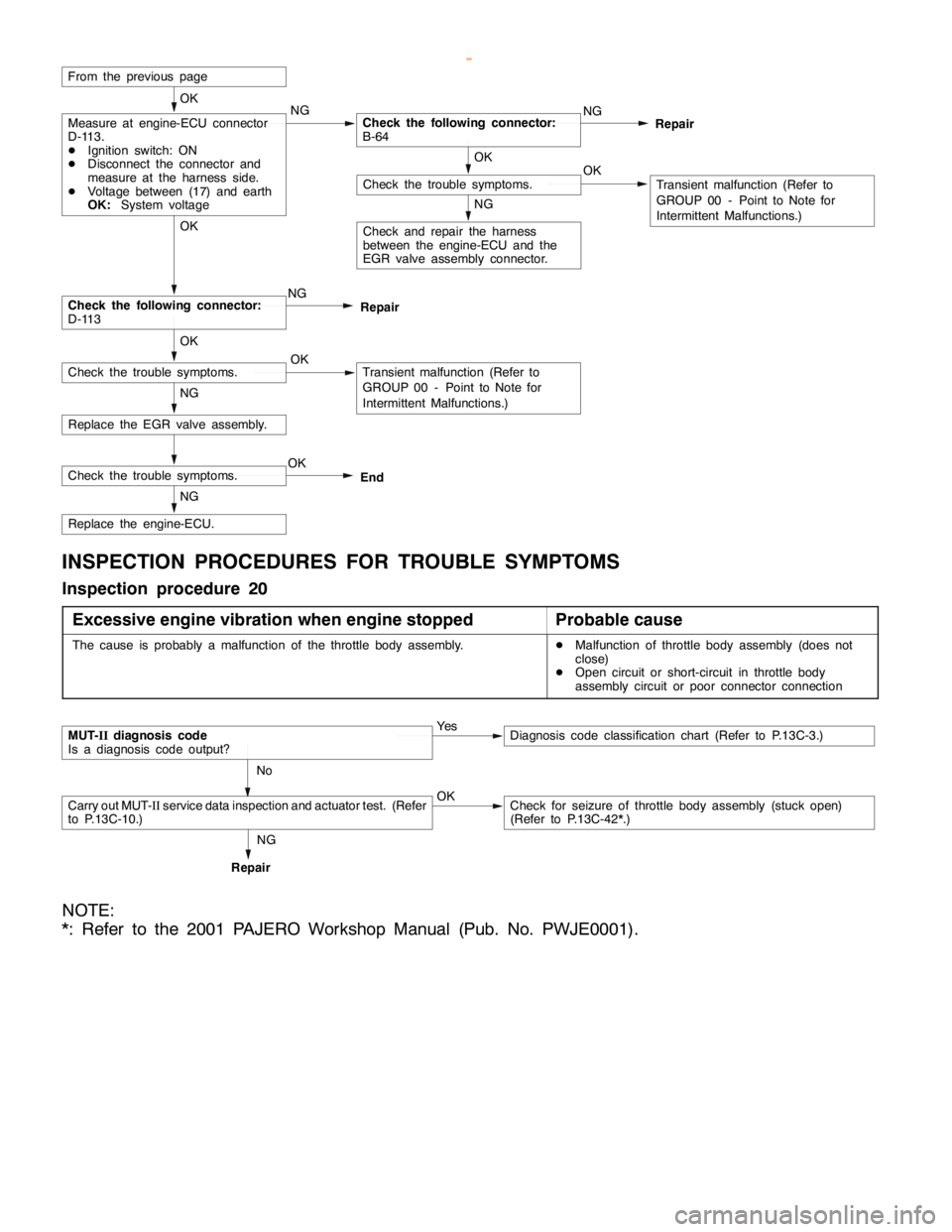
DIESEL FUEL <4M4> -Troubleshooting13C-9
Replace the engine-ECU.
Replace the EGR valve assembly.NG
Check the following connector:
D-113NG OK
Check and repair the harness
between the engine-ECU and the
EGR valve assembly connector.
NG
OKCheck the trouble symptoms.
OK
Transient malfunction (Refer to
GROUP 00 - Point to Note for
Intermittent Malfunctions.)
From the previous page
NGMeasure at engine-ECU connector
D-113.
DIgnition switch: ON
DDisconnect the connector and
measure at the harness side.
DVoltage between (17) and earth
OK:System voltageCheck the following connector:
B-64NG
Repair OK
NG
OKCheck the trouble symptoms.Transient malfunction (Refer to
GROUP 00 - Point to Note for
Intermittent Malfunctions.) OKRepair
Check the trouble symptoms.OK
End
INSPECTION PROCEDURES FOR TROUBLE SYMPTOMS
Inspection procedure 20
Excessive engine vibration when engine stopped
Probable cause
The cause is probably a malfunction of the throttle body assembly.DMalfunction of throttle body assembly (does not
close)
DOpen circuit or short-circuit in throttle body
assembly circuit or poor connector connection
MUT-IIdiagnosis code
Is a diagnosis code output?Ye sDiagnosis code classification chart (Refer to P.13C-3.)
No
Carry out MUT-IIservice data inspection and actuator test. (Refer
to P.13C-10.)OKCheck for seizure of throttle body assembly (stuck open)
(Refer to P.13C-42*.)
RepairNG
NOTE:
*: Refer to the 2001 PAJERO Workshop Manual (Pub. No. PWJE0001).
www.WorkshopManuals.co.uk
Purchased from www.WorkshopManuals.co.uk