2000 MERCEDES-BENZ SLK320 wheel
[x] Cancel search: wheelPage 63 of 273
60 Restraint systems
Te ch n ica l
data Instruments
and controlsOperationDrivingInstrument
cluster displayPractical hints Car care Index
Safety guidelines for the seat belt, emergency
tensioning retractor and airbag
If you believe that, even with the use of these
guidelines, it would be safer for your front
passenger seat occupant to have the passenger side
door mounted side airbag deactivated, then
deactivation can be accomplished upon your
written election to do so at your authorized
Mercedes-Benz Center at an additional cost. Please
contact your local authorized Mercedes-Benz
Center or call our Client Assistance Center at
1-800-FOR-MERCedes (1-800-367-6372) for details.Wa r n i n g !
• Damaged seat belts or belts that were highly
stressed in an accident must be replaced and
their anchoring points must also be checked.
Use only belts installed or supplied by an
authorized Mercedes-Benz Center.
• Airbags and ETR’s are designed to function on
a one-time-only basis. An airbag or emergency
tensioning retractor (ETR) that was activated
must be replaced.• Do not pass belts over sharp edges.• Do not make any modification that could
change the effectiveness of the belts.• No modifications of any kind may be made to
any components or wiring of the “SRS”. This
includes changing or removing any component
or part of the “SRS”, the installation of
additional trim material, badges etc. over the
steering wheel hub, passenger airbag cover, or
door trim panels, and installation of additional
electrical / electronic equipment on or near
“SRS” components and wiring. Keep area
between airbags and occupants free of objects
(e.g. packages, purses, umbrellas, etc.).
Page 64 of 273
61 Restraint systems
Te ch n ica l
data Instruments
and controlsOperationDrivingInstrument
cluster displayPractical hints Car care IndexWhen you sell the vehicle we strongly urge you to give
notice to the subsequent owner that it is equipped with
an “SRS” by a lerting him to th e applicabl e section in t he
Operator’s Manual.
• An airbag system component within the
steering wheel gets hot after the airbag has
inflated. Do not touch.• Improper work on the system, including
incorrect installation and removal, can lead to
possible injury through an unintended
activation of the “SRS”.• In addition, through improper work there is
the risk of rendering the “SRS” inoperative or
causing unintended airbag deployment. Work
on the “SRS” must therefore only be performed
by an authorized Mercedes-Benz Center.
• For your protection and the protection of
others, when scrapping the airbag unit or
emergency tensioning retractor, our safety
instructions must be followed. These
instructions are available at your authorized
Mercedes-Benz Center.• Given the considerable deployment speed and
the textile structure of the airbags, there is the
possibility of abrasions or other injuries
resulting from airbag deployment.
Page 67 of 273
64 Adjusting telescoping steering column
Te ch n ica l
data Instruments
and controlsOperationDrivingInstrument
cluster displayPractical hints Car care Index
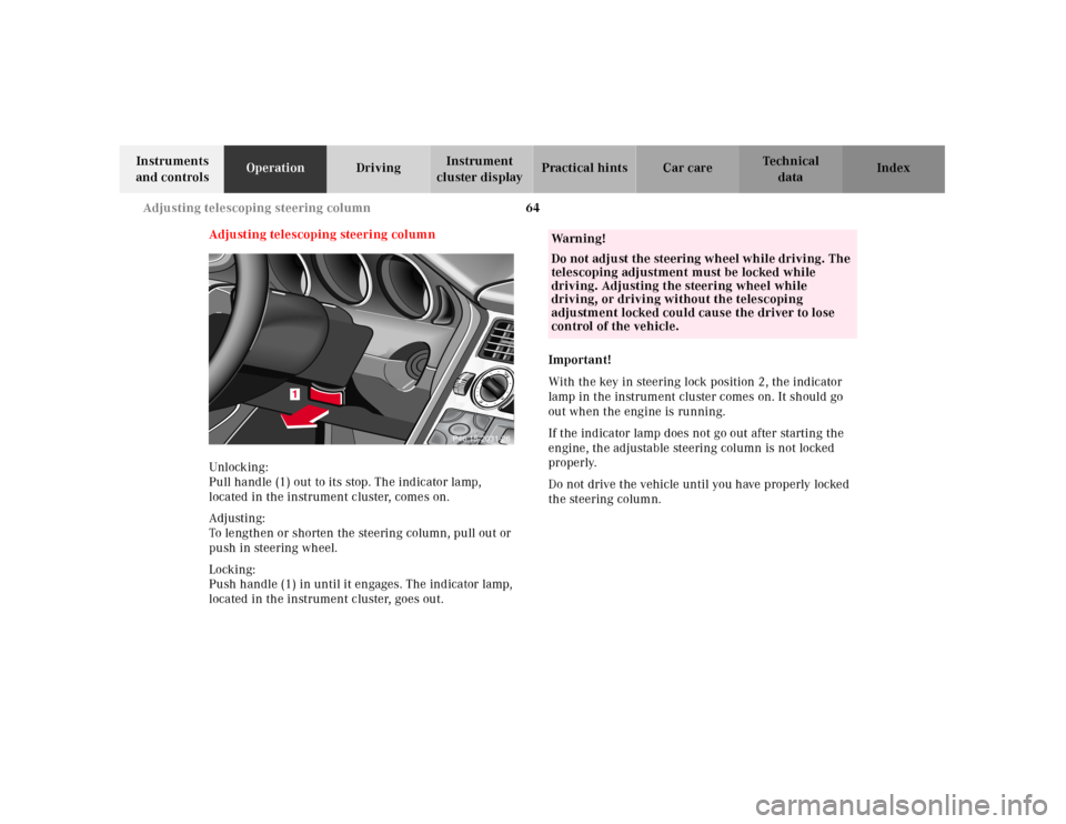
Adjusting telescoping steering column
Unlocking:
Pull handle (1) out to its stop. The indicator lamp,
located in the instrument cluster, comes on.
Adjusting:
To lengthen or shorten the steering column, pull out or
push in steering wheel.
Locking:
Push handle (1) in until it engages. The indicator lamp,
located in the instrument cluster, goes out.Important!
With the key in steering lock position 2, the indicator
lamp in the instrument cluster comes on. It should go
out when the engine is running.
If the indicator lamp does not go out after starting the
engine, the adjustable steering column is not locked
properly.
Do not drive the vehicle until you have properly locked
the steering column.
AUDIO
TEL
AUDIO
TEL
1
AUDIO
TEL
AUDIO
TEL
P46.15-2031-26
Wa r n i n g !
Do not adjust the steering wheel while driving. The
telescoping adjustment must be locked while
driving. Adjusting the steering wheel while
driving, or driving without the telescoping
adjustment locked could cause the driver to lose
control of the vehicle.
Page 84 of 273
81 Combination switch
Te ch n ica l
data Instruments
and controlsOperationDrivingInstrument
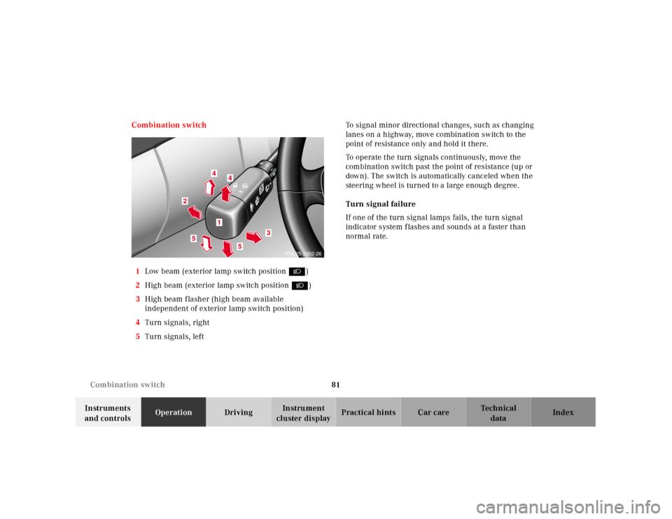
cluster displayPractical hints Car care Index Combination switch
1Low beam (exterior lamp switch position B)
2High beam (exterior lamp switch position B)
3High beam flasher (high beam available
independent of exterior lamp switch position)
4Turn signals, right
5Turn signals, leftTo signal minor directional changes, such as changing
lanes on a highway, move combination switch to the
point of resistance only and hold it there.
To operate the turn signals continuously, move the
combination switch past the point of resistance (up or
down). The switch is automatically canceled when the
steering wheel is turned to a large enough degree.
Turn signal failure
If one of the turn signal lamps fails, the turn signal
indicator system flashes and sounds at a faster than
normal rate.
2
3
4
4
5
5
1
P54.25-2302-26
Page 88 of 273
85 Climate control
Te ch n ica l
data Instruments
and controlsOperationDrivingInstrument
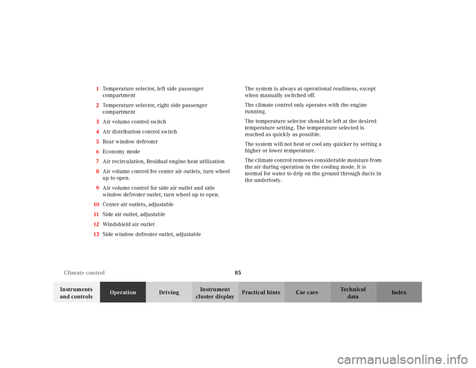
cluster displayPractical hints Car care Index 1Temperature selector, left side passenger
compartment
2Temperature selector, right side passenger
compartment
3Air volume control switch
4Air distribution control switch
5Rear window defroster
6Economy mode
7Air recirculation, Residual engine heat utilization
8Air volume control for center air outlets, turn wheel
up to open.
9Air volume control for side air outlet and side
window defroster outlet, turn wheel up to open.
10Center air outlets, adjustable
11Side air outlet, adjustable
12Windshield air outlet
13Side window defroster outlet, adjustableThe system is always at operational readiness, except
when manually switched off.
The climate control only operates with the engine
running.
The temperature selector should be left at the desired
temperature setting. The temperature selected is
reached as quickly as possible.
The system will not h eat or cool a ny quicker by setting a
higher or lower temperature.
The climate control removes considerable moisture from
the air during operation in the cooling mode. It is
normal for water to drip on the ground through ducts in
the underbody.
Page 143 of 273
140 Steering lock
Te ch n ica l
data Instruments
and controlsOperationDrivingInstrument
cluster displayPractical hints Car care Index
Steering lock
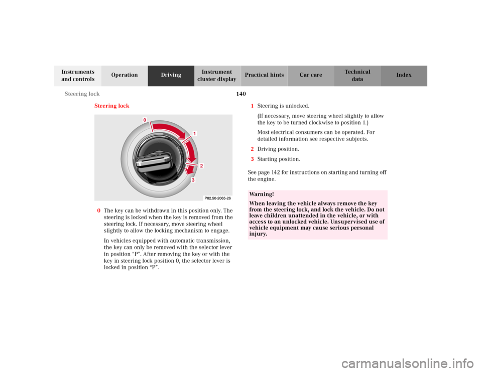
0The key can be withdrawn in this position only. The
steering is l ocked w hen th e key is removed f rom th e
steering lock. If necessary, move steering wheel
slightly to allow the locking mechanism to engage.
In vehicles equipped with automatic transmission,
the key can only be removed with the selector lever
in position “P”. After removing the key or with the
key in steering lock position 0, the selector lever is
locked in position “P”.1Steering is unlocked.
(If necessary, move steering wheel slightly to allow
the key to be turned clockwise to position 1.)
Most electrical consumers can be operated. For
detailed information see respective subjects.
2Driving position.
3Starting position.
See page 142 for instructions on starting and turning off
the engine.
2
3
0
1
Wa r n i n g !
When leaving the vehicle always remove the key
from the steering lock, and lock the vehicle. Do not
leave children unattended in the vehicle, or with
access to an unlocked vehicle. Unsupervised use of
vehicle equipment may cause serious personal
injury.
Page 146 of 273
143 Manual transmission
Te ch n ica l
data Instruments
and controlsOperationDrivingInstrument
cluster displayPractical hints Car care Index Manual transmission
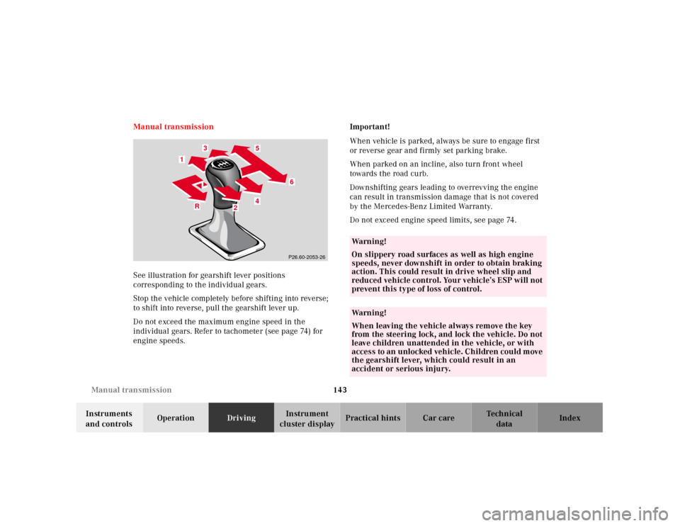
See illustration for gearshift lever positions
corresponding to the individual gears.
Stop the vehicle completely before shifting into reverse;
to shift into reverse, pull the gearshift lever up.
Do not exceed the maximum engine speed in the
individual gears. Refer to tachometer (see page 74) for
engine speeds.Important!
When vehicle is parked, always be sure to engage first
or reverse gear and firmly set parking brake.
When parked on an incline, also turn front wheel
towards the road curb.
Downshifting gears leading to overrevving the engine
can result in transmission damage that is not covered
by the Mercedes-Benz Limited Warranty.
Do not exceed engine speed limits, see page 74.
4 1
6
5
1
3
R
4
R4
6
13
5
2
2
P26.60-2053-26
Wa r n i n g !
On slippery road surfaces as well as high engine
speeds, never downshift in order to obtain braking
action. This could result in drive wheel slip and
reduced vehicle control. Your vehicle’s ESP will not
prevent this type of loss of control.Wa r n i n g !
When leaving the vehicle always remove the key
from the steering lock, and lock the vehicle. Do not
leave children unattended in the vehicle, or with
access to an u nlocked veh ic le. Ch ildren cou ld m ove
the gearshift lever, which could result in an
accident or serious injury.
Page 149 of 273
146 Automatic transmission
Te ch n ica l
data Instruments
and controlsOperationDrivingInstrument
cluster displayPractical hints Car care Index
Stopping
For brief stops, e.g. at traffic lights, leave the
transmission in gear and hold vehicle with the service
brake.
For longer stops with the engine idling, shift into “N”
or “P” and hold the vehicle with the service brake.
When stopping the vehicle on an uphill gradient, do not
hold it with the accelerator, use the brake. This avoids
unnecessary transmission heat build up.
Maneuvering
To maneuver in tight areas, e.g. when pulling into a
parking space, control the vehicle speed by gradually
releasing the brakes. Accelerate gently and never
abruptly step on the accelerator.
To rock a vehicle out of soft ground (mud or snow),
alternately shift from forward to reverse, while applying
only slight partial throttle.
Rocking a vehicle free in this manner may cause the
ABS or traction system malfunction indicator lamp to
come on. Turn off and restart the engine to clear the
malfunction indication.
Wa r n i n g !
Getting out of your vehicle with the selector lever
not fully engaged in position “P” is dangerous.
Also, when parked on an incline, posi tion “P” alone
may not prevent your vehicle from moving,
possibly hitting people or objects.Always set t he parki ng brake in addi tion to sh ifting
to position “P”, see page 153 for parking brake. When parked on an incline, also turn front wheel
towards the road curb.Wa r n i n g !
When leaving the vehicle always remove the key
from the steering lock, and lock the vehicle. Do not
leave children unattended in the vehicle, or with
access to an u nlocked veh ic le. Ch ildren cou ld m ove
the gear selector lever from position “P”, which
could result in an accident or serious injury.