2000 MERCEDES-BENZ SLK CLASS steering wheel
[x] Cancel search: steering wheelPage 163 of 273

160 Driving instructions
Te ch n ica l
data Instruments
and controlsOperationDrivingInstrument
cluster displayPractical hints Car care Index
Snow chains
Use only snow chains that are tested and recommended
by Mercedes-Benz. Your authorized Mercedes-Benz
Center will be glad to advise you on this subject.
Chains should only be used on the rear wheels. Follow
the manufacturer’s mounting instructions.
Snow chains should only be driven on snow covered
roads at speeds not to exceed 30 mph (50 km / h).
Remove chains as soon as possible when driving on
roads without snow.
When driving with snow chains, press the ESP control
switch to OFF, see page 172.
Important!
Use of snow chains is not permissible with tire size
225 / 50 R 16, with th e col lapsib le spa re tire, or with tire
size 245 / 40 ZR 17 (Sport Package).Winter driving instructions
The most important rule for slippery or icy roads is to
drive sensibly and to avoid abrupt acceleration, braking
and steering maneuvers. Do not use the cruise control
system under such conditions.
When the vehicle is in danger of skidding, move
selector lever to position “N” or in case of manual
transmission declutch. Try to keep the vehicle under
control by corrective steering action.
Road salts and chemicals can adversely affect braking
efficiency. Increased pedal force may become necessary
to produce the normal brake effect. We therefore
recommend depressing the brake pedal periodically
when traveling at length on salt-strewn roads. This can
bring road salt impaired braking efficiency back to
normal. A prerequisite is, however, that this be done
without endangering other drivers on the road.
If t he veh icle is pa rked af te r b eing driven on sal t trea ted
road s, th e braking ef f ic iency should be tested as soon a s
possible after driving is resumed while observing the
safety rules in the previous paragraph.
Page 171 of 273

168 Driving systems
Te ch n ica l
data Instruments
and controlsOperationDrivingInstrument
cluster displayPractical hints Car care Index
Antilock brake system (ABS)
Important!
The ABS improves steering control of the vehicle during
hard braking maneuvers.
The ABS prevents the wheels from locking up above a
vehicle speed of approximately 5 mph (8 km / h)
independent of road surface conditions.At the instant one of the wheels is about to lock up, a
slight pulsation can be felt in the brake pedal,
indicating that the ABS is in the regulating mode. Keep
firm and steady pressure on the brake pedal while
experiencing the pulsation.
Continuous steady brake pedal pressure results in
applying the advantages of the ABS, namely braking
power and ability to steer the vehicle.
In the case of an emergency brake maneuver keep
continuous full pressure on the brake pedal. In this
manner only can the ABS be most effective.
On slippery road surfaces, the ABS will respond even
with light brake pedal pressure because of the
increased likelihood of locking wheels. The pulsating
brake pedal can be an indication of hazardous road
conditions and functions as a reminder to take extra
care while driving.
Wa r n i n g !
Do not pump the brake pedal, rather use firm,
steady brake pedal pressure. Pumping the brake
pedal defeats the purpose for ABS and significantly
reduces braking effectiveness.
Page 173 of 273

170 Driving systems
Te ch n ica l
data Instruments
and controlsOperationDrivingInstrument
cluster displayPractical hints Car care Index
Electronic stability program (ESP)
The ESP enhances directional control and reduces
driving wheel spin of the vehicle under various driving
conditions.
Over / understeering of the vehicle is counteracted by
applying brakes to the appropriate wheel to create a
countervailing vehicle movement. Engine torque is also
limited. The ESP warning lamp, located in the
speedometer dial, starts to flash.Important!
If the ESP warning lampv flashes:
•During take-off apply as little throttle as possible.
•While driving ease up on the accelerator.
•Adapt your speed and driving to the prevailing road
conditions.
•Do not switch off the ESP.
Caution!
If the vehicle is towed with the front axle raised (see
page 214), the engine must be shut off (key in steering
lock position 0 or 1). Otherwise, the ESP will
immediately be engaged and will apply the rear wheel
brakes.
Wa r n i n g !
ESP cannot prevent the natural laws of physics
from acting on the vehicle, nor can it increase the
traction afforded. The ESP cannot prevent
accidents, including those resulting from excessive
speed in turns, or aquaplaning. Only a safe,
at tentive, and ski llful driver can prevent ac cidents.
The capabilities of an ESP equipped vehicle must
never be exploited in a reckless or dangerous
manner which could jeopardize the user’s safety or
the safety of others.
Page 174 of 273

171 Driving systems
Te ch n ica l
data Instruments
and controlsOperationDrivingInstrument
cluster displayPractical hints Car care Index Notes:
Th e m alf unction indicator l amp for t he ESP is combined
with that of the BAS.
The yellow BAS / ESP malfunction indicator lamp in the
instrument cluster and the yellow ESP warning
lampv in the speedometer dial come on with the
key in steering lock position 2. They should go out with
the engine running.
If the BAS / ESP malfunction indicator lamp comes on
continuously with the engine running, a malfunction
has been detected in either system. Only partial engine
output will be available.
If the BAS malfunctions, the brake system functions in
the usual manner, but without BAS.
Have the BAS or ESP checked at your authorized
Mercedes-Benz Center as soon as possible.
With the ABS malfunctioning, the ESP is also switched
off.Driving the vehicle with varied size tires will cause the
wheels to rotate at different speeds, therefore the ESP
may activate (yellow ESP warning lamp in speedometer
dial comes on). For this reason, all wheels, including the
spare wheel, must have the same tire size.
When testing the parking brake on a brake test
dynamometer, the engine must be shut off. Otherwise,
the ESP will immediately be engaged and will apply the
rear wheel brakes.
In winter operation, the maximum effectiveness of the
ESP is only achieved with Mercedes-Benz recommended
M+S rated radial-ply tires and / or snow chains.
Synchronizing ESP
If the power supply was interrupted (battery
disconnected or empty), the BAS / ESP malfunction
indicator lamp may be illuminated with the engine
running.
Turn steering wheel completely to the left and then to
the right. The BAS / ESP malfunction indicator lamp
should go out.
Page 210 of 273

207 Tires, wheels
Te ch n ica l
data Instruments
and controlsOperation DrivingInstrument
cluster displayPractical hintsCar care Index Inflating the collapsible spare tire
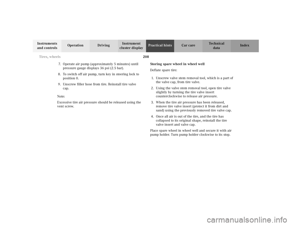
The air pump is located inside the wheel well in the
trunk.
1Filler hose
2Electrical plug
3Pressure gauge with vent screw1.Remove air pump from storage compartment inside
trunk.
2.Open lid and pull out air hose with pressure gauge
and electrical plug.
Observe instructions on air pump label.
3.Unscrew tire valve cap from spare wheel tire valve.
4.Screw filler hose onto tire valve.
5.Plug air pump electrical plug into vehicle cigar
lighter.
6.To switch on air pump, turn key in steering lock to
position 1.
Important!
Do not start engine.
P40.10-2124-26
1
0
45 6max. 6 min
A 170 584 01 38 AIR COMPRESSOR 23
Mercedes-Benz
2
3
2 1
1
2,5 bar
36 psi1
0 23
4
5
620PSI
BAR40
60
80
LUFTPRESSER12
12
3
Wa r n i n g !
To prevent possible injury when unscrewing air
pump filler hose from tire valve after inflating the
tire, use a rag since the tire valve could be hot.
Page 211 of 273

208 Tires, wheels
Te ch n ica l
data Instruments
and controlsOperation DrivingInstrument
cluster displayPractical hintsCar care Index
7.Operate air pump (approximately 5 minutes) until
pressure gauge displays 36 psi (2.5 bar).
8.To switch off air pump, turn key in steering lock to
position 0.
9.Unscrew filler hose from tire. Reinstall tire valve
cap.
Note:
Excessive tire air pressure should be released using the
vent screw.Storing spare wheel in wheel well
Deflate spare tire:
1.Unscrew valve stem removal tool, which is a part of
the valve cap, from tire valve.
2.Using the valve stem removal tool, open tire valve
slightly by turning the tire valve insert
counterclockwise to release air pressure.
3.When the tire air pressure has been released,
remove tire valve insert (protect it from dirt and
sand) using the previously removed tire valve cap.
4.Once all air is out of the tire, and the tire has
collapsed to its original shape, reinstall the tire
valve insert and valve cap.
Place spare wheel in wheel well and secure it with air
pump holder. Turn pump holder clockwise to its stop.
Page 218 of 273

215 Towing the vehicle
Te ch n ica l
data Instruments
and controlsOperation DrivingInstrument
cluster displayPractical hintsCar care Index Sport Package
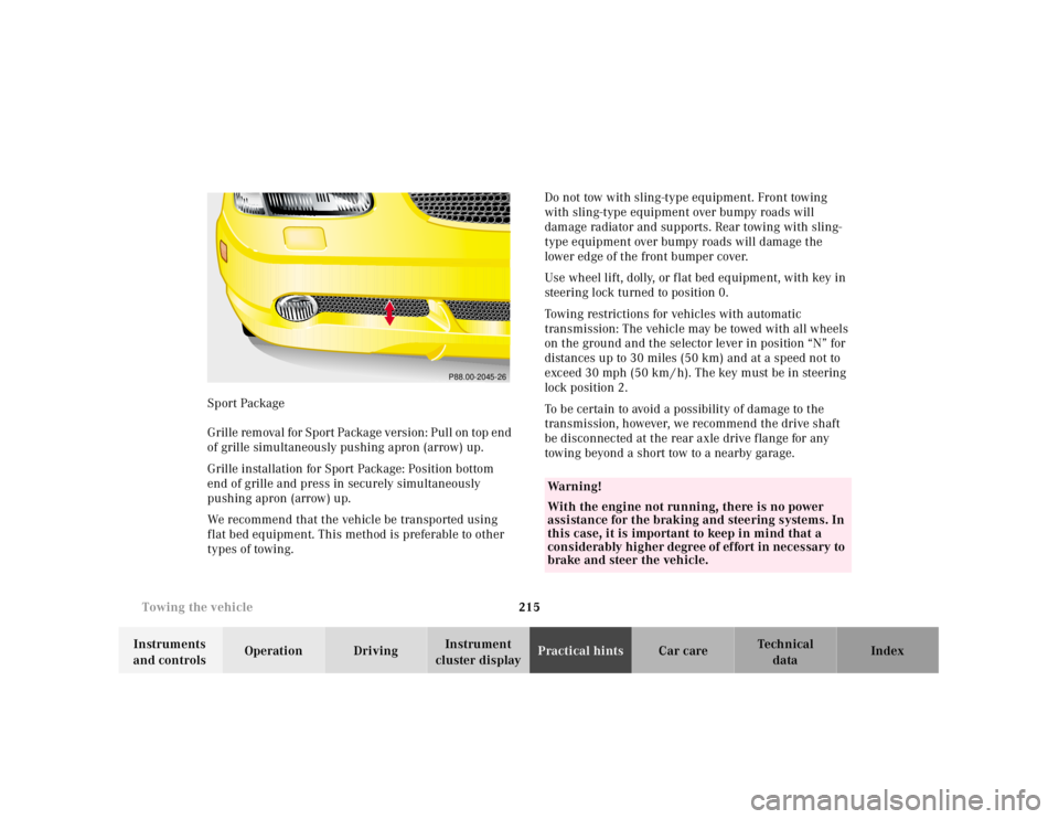
G r il l e re m ova l f or S p or t Pa cka g e v e rs i on : P u l l on t op e n d
of grille simultaneously pushing apron (arrow) up.
Grille installation for Sport Package: Position bottom
end of grille and press in securely simultaneously
pushing apron (arrow) up.
We recommend that the vehicle be transported using
f lat bed equipment. This method is preferable to other
types of towing.Do not tow with sling-type equipment. Front towing
with sling-type equipment over bumpy roads will
damage radiator and supports. Rear towing with sling-
type equipment over bumpy roads will damage the
lower edge of the front bumper cover.
Use wheel lift, dolly, or f lat bed equipment, with key in
steering lock turned to position 0.
Towing restrictions for vehicles with automatic
transmission: The vehicle may be towed with all wheels
on the ground and the selector lever in position “N” for
distances up to 30 miles (50 km) and at a speed not to
exceed 30 mph (50 km / h). The key must be in steering
lock position 2.
To be certain to avoid a possibility of damage to the
transmission, however, we recommend the drive shaft
be disconnected at the rear axle drive f lange for any
towing beyond a short tow to a nearby garage.
P88.00-2045-26
Wa r n i n g !
With the engine not running, there is no power
assistance for the braking and steering systems. In
this case, it is important to keep in mind that a
considerably higher degree of effort in necessary to
brake and steer the vehicle.
Page 219 of 273

216 Towing the vehicle
Te ch n ica l
data Instruments
and controlsOperation DrivingInstrument
cluster displayPractical hintsCar care Index
Important!
When towing the vehicle, please, note the following:
With the automatic central locking activated and the
key in steering lock position 2, the vehicle doors lock if
the left front wheel as well as the right rear wheel are
turning at vehicle speeds of approximately 9 mph
(15 km / h) or more.
To prevent the vehicle door locks from locking,
deactivate the automatic central locking.Note:
To signal turns while being towed with hazard warning
f lash er in u se, turn key in steering l ock to position 2 a nd
activate combination switch for left or right turn signal
in usual manner – only the selected turn signal will
operate. Upon canceling the turn signal, the hazard
warning flasher will operate again.
Caution!
If the vehicle is towed with the front axle raised, the
engine must be shut off (key in steering lock position 0
or 1). Otherwise, the ESP will immediately be engaged
and will apply the rear wheel brakes. Switch off the
tow-away alarm as well as the ESP, see page 37 and 170.