2000 MERCEDES-BENZ SL600 warning
[x] Cancel search: warningPage 215 of 297
211 Malfunction and indicator lamps
Technical
data Instruments
and controlsOperation DrivingInstrument
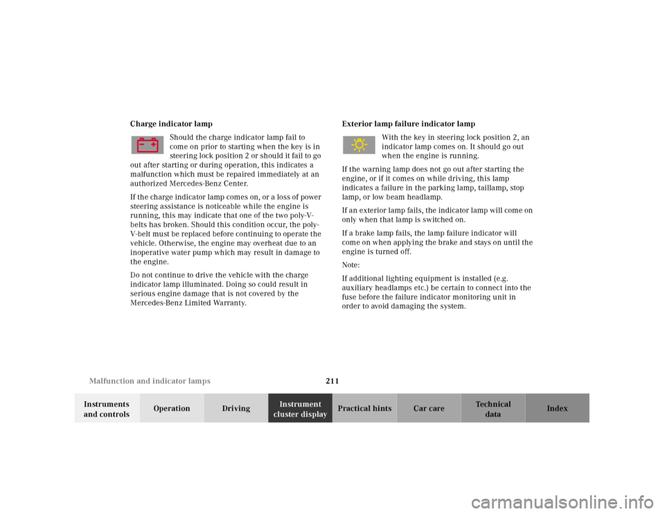
cluster displayPractical hints Car care Index Charge indicator lamp
Should the charge indicator lamp fail to
come on prior to starting when the key is in
steering l ock position 2 or sh ou ld it fa il to go
out after starting or during operation, this indicates a
malfunction which must be repaired immediately at an
authorized Mercedes-Benz Center.
If th e ch arge indica tor l amp com es on, or a loss of power
steering assistance is noticeable while the engine is
running, this may indicate that one of the two poly-V-
belts has broken. Should this condition occur, the poly-
V-belt mu st be repl aced before continuing to operate t he
vehicle. Otherwise, the engine may overheat due to an
inoperative water pump which may result in damage to
the engine.
Do not continue to drive the vehicle with the charge
indicator lamp illuminated. Doing so could result in
serious engine damage that is not covered by the
Mercedes-Benz Limited Warranty.Exterior lamp failure indicator lamp
With the key in steering lock position 2, an
indicator lamp comes on. It should go out
when the engine is running.
If the warning lamp does not go out after starting the
engine, or if it comes on while driving, this lamp
indicates a failure in the parking lamp, taillamp, stop
lamp, or low beam headlamp.
If a n exterior lamp fa ils, the indica tor lamp will com e on
only when that lamp is switched on.
If a brake lamp fails, the lamp failure indicator will
come on when applying the brake and stays on until the
engine is turned off.
Note:
If additional lighting equipment is installed (e.g.
auxiliary headlamps etc.) be certain to connect into the
fuse before the failure indicator monitoring unit in
order to avoid damaging the system.
Page 216 of 297
212 Malfunction and warning messages
Technical
data Instruments
and controlsOperation DrivingInstrument
cluster displayPractical hints Car care Index
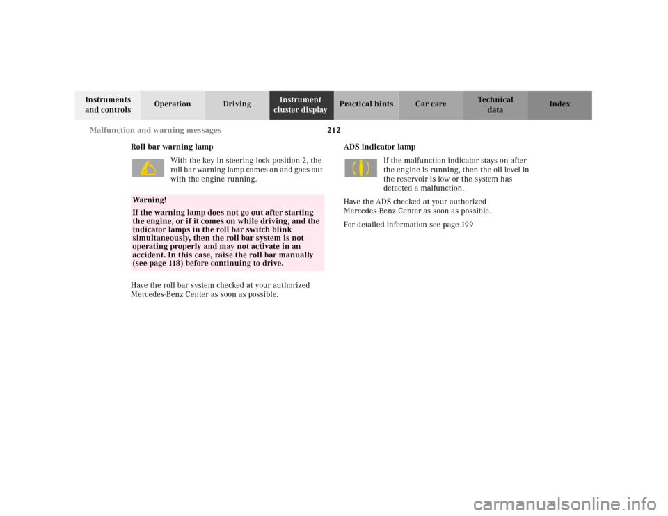
Roll bar warning lamp
With the key in steering lock position 2, the
roll bar warning lamp comes on and goes out
with the engine running.
Have the roll bar system checked at your authorized
Mercedes-Benz Center as soon as possible.ADS indicator lamp
If the malfunction indicator stays on after
the engine is running, then the oil level in
the reservoir is low or the system has
detected a malfunction.
Have the ADS checked at your authorized
Mercedes-Benz Center as soon as possible.
For detailed information see page 199
Wa r n i n g !
If the warning lamp does not go out after starting
the engine, or if it comes on while driving, and the
indicator lamps in the roll bar switch blink
simultaneously, then the roll bar system is not
operating properly and may not activate in an
accident. In this case, raise the roll bar manually
(see page 118) before continuing to drive.
Page 217 of 297
213 Malfunction and warning messages
Technical
data Instruments
and controlsOperation DrivingInstrument
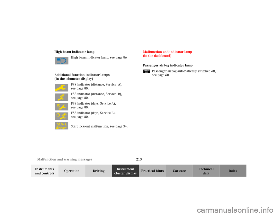
cluster displayPractical hints Car care Index High beam indicator lamp
High beam indicator lamp, see page 86
Additional function indicator lamps
(in the odometer display)
FSS indicator (distance, Service A),
seepage80.
FSS indicator (distance, Service B),
seepage80.
FSS indicator (days, Service A),
seepage80.
FSS indicator (days, Service B),
seepage80.
Start lock-out malfunction, see page 34.Malfunction and indicator lamp
(in the dashboard)
Passenger airbag indicator lamp
üPassenger airbag automatically switched off,
see page 60.
Page 226 of 297
222 Checking engine oil level
Technical
data Instruments
and controlsOperation DrivingInstrument
cluster displayPractical hintsCar care Index
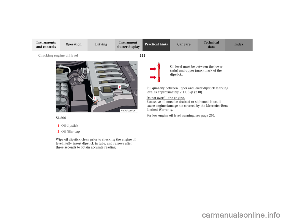
SL 600
1Oil dipstick
2Oil filler cap
Wipe oil dipstick clean prior to checking the engine oil
level. Fully insert dipstick in tube, and remove after
three seconds to obtain accurate reading.Oil level must be between the lower
(min) and upper (max) mark of the
dipstick.
Fill qu antity b etween u pper a nd l ower dipstick m arking
level is approximately 2.1 US qt (2.0l).
Do not overfill the engine.
Excessive oil must be drained or siphoned. It could
cause engine damage not covered by the Mercedes-Benz
Limited Warranty.
For low engine oil level warning, see page 210.
MERCEDES BENZ
MERCEDES BENZ
1
2P18.40-0258-26
Page 234 of 297
230 Tires, Wheels
Technical
data Instruments
and controlsOperation DrivingInstrument
cluster displayPractical hintsCar care Index
Changing wheelsMove vehicle to a level area which is a safe distance
from the roadway.
1. Firmly set parking brake, raise roll bar, and turn on
hazard warning f lasher.
2. Move selector lever to position “P”.
3. While engine is running, depress wheel change
switch for level control. The indicator lamp in the
sw it ch a n d t h e A D S m a l f u n c t i on i n d i c a to r l a mp l ig h t
up.
4. Turn off engine.
5. Prevent vehicle from rolling away by blocking
wheels with wheel chocks (not supplied with
vehicle) or sizable wood block or stone. When
changing a wheel on a hill, place chocks on the
downhill side blocking both wheels of the other
axl e. On a l evel road, pl ace one ch ock in front of a nd
one behind the wheel that is diagonally opposite to
the wheel being changed.
The jack is designed exclusively for jacking up the
veh icle at the jack tu bes bui lt into eith er si de of th e
vehicle. To help avoid personal injury, use the jack
only to lift the vehicle during a wheel change.
Never get beneath the vehicle while it is supported
by th e jack. Keep hands and feet away from the area
under the lifted vehicle. Always firmly set parking
brake and block wheels before raising vehicle with
jack.Do not disengage parking brake whi le th e vehic le is
raised. Be certain that the jack is always vertical
when in use, especially on hills. Always try to use
the jack on level surface. Be sure that the jack arm
is fully inserted in the jack tube. Always lower the
vehicle onto sufficient capacity jackstands before
working under the vehicle.Before working on the vehicle, e.g. when changing
wheels, the roll bar should be raised with the
switch, and the key be removed from the steering
lock, to prevent possible injury.
Page 243 of 297
239 Jump starting
Technical
data Instruments
and controlsOperation DrivingInstrument
cluster displayPractical hintsCar care Index Proceed as follows:
1. Position the vehicle with the charged battery so that
the jumper cables will reach, but never let the
vehicles touch. Make sure the jumper cables do not
have loose or missing unsulation.
2. On both vehicles:
• Turn off engine and all lights and accessories,
except hazard warning flashers or work lights.
• Apply parking brake and shift selector lever to
position “P”.
Important!
3. Clamp one end of the first jumper cable to the
positive (+) terminal of the discharged battery and
the other end to the positive (+) terminal of the
charged battery. Make sure the cable clamps do not
touch any other metal parts.
4. Clamp one end of the second jumper cable to the
grounded negative (-) terminal of the charged
battery and the final connection to the negative (-)
terminal of the discharged battery.Important!
5. Start engine of the vehicle with the charged battery
and run at high idle. Make sure the cables are not
on or near pulleys, fans, or other parts that will
move when the engine is started. Allow the
disch arge d ba ttery to ch arge for a few minu tes. Sta rt
engine of the disabled vehicle in the usual manner.
6. After the engine has started, remove jumper cables
by exactly reversing the above installation
sequence, starting with the last connection made
first. When removing each clamp, make sure that it
does not touch any other metal while the other end
is still attached.
Note:
If engine does not run after several unsuccessful
starting attempts, have it checked at the nearest
authorized Mercedes-Benz Center.
Excessive unburned fuel may damage the catalytic
converter.
Page 245 of 297
241 Towing the vehicle
Technical
data Instruments
and controlsOperation DrivingInstrument
cluster displayPractical hintsCar care Index The vehicle may be towed with all wheels on the ground
and the selector lever in position “N” for distances up to
30 miles (50 km) and at a speed not to exceed 30 mph
(50 km/h). The key must be in steering lock position 2.
To be certain to avoid a possibility of damage to the
transmission, however, we recommend the drive shaft
be disconnected at the rear axle drive f lange for any
towing beyond a short tow to a nearby garage.
Do not tow with sling-type equipment. Towing with
sling-type equipment over bumpy roads will damage
radiator and supports.
The use of wheel lift equipment will damage engine oil
pan.
Important!
When towing the vehicle, please, note the following:
With the automatic central locking activated and the
key in steering lock position 2, the vehicle doors lock if
the left front wheel as well as the right rear wheel are
tu rning a t veh ic le speeds of approx . 9 mph (15 k m/h) or
more.
To prevent the vehicle door locks from locking,
deactivate the automatic central locking.When transporting vehicle on flat bed equipment, the
front end of the vehicle must be loaded first. Additional
ramping may be required for loading to protect bumper
fascia.
Note:
To signal turns while being towed with hazard warning
f lash er in u se, turn key in steering l ock to position 2 a nd
activate combination switch for left or right turn signal
in usual manner – only the selected turn signal will
operate.
Upon canceling the turn signal, the hazard warning
f lasher will operate again.
Wa r n i n g !
With the engine not running, there is no power
assistance for the braking and steering systems. In
this case, it is important to keep in mind that a
considerably higher degree of effort in necessary to
brake and steer the vehicle.
Page 289 of 297
285
Technical
data Instruments
and controlsOperation DrivingInstrument
cluster displayPractical hints Car careIndex
Index
AABS (Antilock brake system) ....................................... 190
Malfunction indicator lamp .....................................208
Adj usting steering c ol umn
Storing steering column position in memory ........ 70
ADS indicator lamp ....................................................... 212
ADS warning lamp ......................................................... 212
Air conditioner refrigerant ...........................................278
Airbags .............................................................................. 60
Airbag OFF indicator lamp ...................................... 213
SRS indicator lamp ...................................................206
Antenna ........................................................................... 151
Antilock brake system (ABS) ....................................... 190
Antitheft alarm system ................................................... 42
Aquaplaning ................................................................... 180
Armrest ........................................................................... 127
Ashtrays .................................................................. 130, 131
Audio system
Anti-theft system ...................................................... 100
Button and soft key operation ................................. 101
Cassette mode ........................................................... 106
CD changer .................................................................110CD mode ..................................................................... 109
Operating and display elements ...............................99
Operating safety ..........................................................98
Operation ............................................................. 98, 102
Radio mode ................................................................ 104
Telephone operation ................................................. 113
Automatic climate control ..............................................90
Air distribution ............................................................95
Air recirculation ..........................................................96
Air volume .................................................................... 95
Basic setting - automatic mode ................................. 93
Defogging windows .....................................................94
Defrosting .....................................................................94
Display and controls ...................................................92
Dust filter .....................................................................97
Rear window defroster ............................................... 95
Residual engine heat utilization ...............................96
Automatic transmission ................................................ 168
Emergency operation ............................................... 174
Fluid level ...................................................................221
Maneuvering ..............................................................172
Program mode selector switch ................................173
Selector lever positions ............................................ 169