2000 MERCEDES-BENZ S55AMG ABS
[x] Cancel search: ABSPage 274 of 421
271 Driving systems
Te ch n ica l
data Instruments
and controlsOperationDrivingInstrument
cluster displayPractical hints Car care Index Brake assist system (BAS)
The BAS is designed to maximize the vehicle’s braking
capability during emergency braking maneuvers by
having maximum power boost applied to the brakes
more quickly in emergency braking conditions than
might otherwise be afforded solely by the driver’s
braking style. This can help reduce braking distances
over what ordinary driving and braking style might do.
The BAS complements the Antilock Brake System (ABS).Applying the brakes very quickly results in maximum
BAS assistance.
To receive the benefit of the system you must apply
continuous full braking power during the stopping
sequence. Do not reduce brake pedal pressure.
Once the brake pedal is released, the BAS is deactivated.
If the BAS warning message is displayed, a malfunction
has been detected in the system. The brake system
functions in the usual manner, but without BAS.
With the ABS malfunctioning, the BAS is also switched
off.
If a BAS warning message is displayed, have the BAS
checked at your authorized Mercedes-Benz Center as
soon as possible.
Wa r n i n g !
BAS cannot prevent the natural laws of physics
from acting on the vehicle, nor can it increase
braking efficiency beyond that afforded by the
condition of the vehicle brakes and tires or the
traction afforded. The BAS cannot prevent
accidents, including those resulting from excessive
speed in turns, following another vehicle too
closely, or aquaplaning. Only a safe, attentive, and
skillful driver can prevent accidents. The
capabilities of a BAS equipped car must never be
exploited in a reckless or dangerous manner which
could jeopardize the user’s safety or the safety of
others.
Page 275 of 421
272 Driving systems
Te ch n ica l
data Instruments
and controlsOperationDrivingInstrument
cluster displayPractical hints Car care Index
Antilock brake system (ABS)
Important!
The ABS improves steering control of the vehicle during
hard braking maneuvers.
The ABS prevents the wheels from locking up above a
vehicle speed of approximately 5 mph (8 km / h)
independent of road surface conditions.At the instant one of the wheels is about to lock up, a
slight pulsation can be felt in the brake pedal,
indicating that the ABS is in the regulating mode. Keep
firm and steady pressure on the brake pedal while
experiencing the pulsation.
Continuous steady brake pedal pressure results in
applying the advantages of the ABS, namely braking
power and ability to steer the vehicle.
In the case of an emergency brake maneuver keep
continuous full pressure on the brake pedal. In this
manner only can the ABS be most effective.
On slippery road surfaces, the ABS will respond even
with light brake pedal pressure because of the
increased likelihood of locking wheels. The pulsating
brake pedal can be an indication of hazardous road
conditions and functions as a reminder to take extra
care while driving.
Wa r n i n g !
Do not pump the brake pedal, rather use firm,
steady brake pedal pressure. Pumping the brake
pedal defeats the purpose for ABS and significantly
reduces braking effectiveness.
Page 276 of 421
273 Driving systems
Te ch n ica l
data Instruments
and controlsOperationDrivingInstrument
cluster displayPractical hints Car care Index ABS control
The ABS malfunction indicator lamp- in the
instrument cluster comes on with the electronic key in
starter switch position 2 and should go out with the
engine running.
When the ABS malfunction indicator lamp in the
instrument cluster comes on while the engine is
running, it indicates that the ABS has detected a
malfunction and has switched off. In this case, the brake
system functions in the usual manner, but without
antilock assistance.
For ABS malfunction indicator lamp, see page 300.
With the ABS malfunctioning, the BAS and ESP are also
switched off. Both malfunction indicator lamps come on
with the engine running.
If the charging voltage falls below 10 volts, the
malfunction indicator lamp comes on and the ABS is
switched off. When the voltage is above this value again,
the malfunction indicator lamp should go out and the
ABS is operational.If the ABS malfunction indicator lamp stays illuminated,
have the system checked at your authorized
Mercedes-Benz Center as soon as possible.
Note:
To alert following vehicles to slippery road conditions
you discover, operate your hazard warning flashers as
appropriate.
Wa r n i n g !
ABS cannot prevent the natural laws of physics
from acting on the vehicle, nor can it increase
braking or steering efficiency beyond that afforded
by the condition of the vehicle brakes and tires or
the traction afforded. The ABS cannot prevent
accidents, including those resulting from excessive
speed in turns, following another vehicle too
closely, or aquaplaning. Only a safe, attentive, and
skillful driver can prevent accidents. The
capabilities of a ABS equipped vehicle must never
be exploited in a reckless or dangerous manner
which could jeopardize the user’s safety or the
safety of others.
Page 278 of 421
275 Driving systems
Te ch n ica l
data Instruments
and controlsOperationDrivingInstrument
cluster displayPractical hints Car care Index Notes:
The yellow ESP warning lampv in the speedometer
dial comes on with the electronic key in starter switch
position 2. It should go out with the engine running.
If the ESP warning message is displayed, a malfunction
has been detected in the system. Only partial engine
output will be available.
Have the ESP checked at your authorized
Mercedes-Benz Center as soon as possible.
For ESP warning message, see page 301.
With the ABS malfunctioning, the ESP is also switched
off.
Driving the vehicle with varied size tires will cause the
wheels to rotate at different speeds, therefore the ESP
may activate (yellow ESP warning lamp in speedometer
dial comes on). For this reason, all wheels, including the
spare wheel, must have the same tire size. When testing the parking brake on a brake test
dynamometer, the engine must be shut off. Otherwise,
the ESP will immediately be engaged and will apply the
rear wheel brakes.
In winter operation, the maximum effectiveness of the
ESP is only achieved with Mercedes-Benz recommended
M+S rated radial-ply tires and / or snow chains.
Synchronizing ESP
If the power supply was interrupted (battery
disconnected or empty), the ESP warning message may
be displayed with the engine running.
Turn steering wheel completely to the left and then to
the right. The ESP warning message should go out.
Page 298 of 421
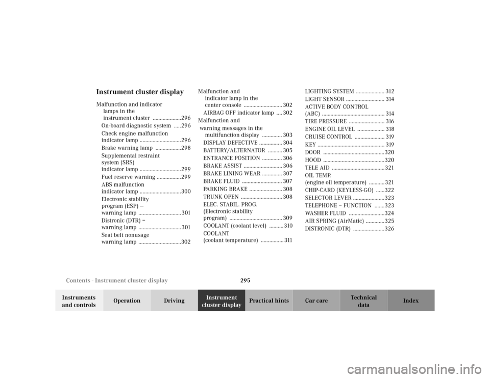
295 Contents - Instrument cluster display
Te ch n ica l
data Instruments
and controlsOperation DrivingInstrument
cluster displayPractical hints Car care Index
Instrument cluster displayMalfunction and indicator
lamps in the
instrument cluster ....................296
On-board diagnostic system .....296
Check engine malfunction
indicator lamp .............................296
Brake warning lamp ..................298
Supplemental restraint
system (SRS)
indicator lamp .............................299
Fuel reserve warning .................299
ABS malfunction
indicator lamp .............................300
Electronic stability
program (ESP) —
warning lamp ..............................301
Distronic (DTR) –
warning lamp ..............................301
Seat belt nonusage
warning lamp ..............................302Malfunction and
indicator lamp in the
center console ........................... 302
AIRBAG OFF indicator lamp .... 302
Malfunction and
warning messages in the
multifunction display .............. 303
DISPLAY DEFECTIVE ................ 304
BATTERY/ALTERNATOR .......... 305
ENTRANCE POSITION .............. 306
BRAKE ASSIST ........................... 306
BRAKE LINING WEAR .............. 307
BRAKE FLUID ............................ 307
PARKING BRAKE ....................... 308
TRUNK OPEN ............................. 308
ELEC. STABIL. PROG.
(Electronic stability
program) ..................................... 309
COOLANT (coolant level) .......... 310
COOLANT
(coolant temperature) ................ 311LIGHTING SYSTEM .................... 312
LIGHT SENSOR ........................... 314
ACTIV E BO DY CO NTROL
(ABC) ............................................ 314
TIRE PRESSURE ......................... 316
ENGINE OIL LEVEL ................... 318
CRUISE CONTROL ..................... 319
KEY ............................................... 319
DOOR ...........................................320
HOOD ...........................................320
TELE AID .....................................321
OIL TEMP.
(engine oil temperature) ...........321
CHIP-CARD (KEYLESS-GO) ......322
SELECTOR LEVER ......................323
TELEPHONE – FUNCTION .......323
WASHER FLUID .........................324
AIR SPRING (AirMatic) .............325
DISTRONIC (DTR) ......................326
Page 303 of 421

300 Malfunction and indicator lamps
Te ch n ica l
data Instruments
and controlsOperation DrivingInstrument
cluster displayPractical hints Car care Index
ABS malfunction indicator lamp
The ABS malfunction indicator lamp in the
instrument cluster comes on with the
electronic key in starter switch position 2
and should go out with the engine running.
When the ABS malfunction indicator lamp symbol and
warning in the instrument cluster remains illuminated
while the engine is running, it indicates that the ABS
has detected a malfunction and has switched off. In this
case, the brake system functions in the usual manner,
but without antilock assistance.
A malfunctioning ABS control unit can possibly affect
the operation of other systems (e.g. Parktronic,
Navigation, Automatic transmission). Be guided
accordingly with respect to the use of those systems and
have the system checked at your authorized
Mercedes-Benz Center as soon as possible.With the ABS malfunctioning, the BAS and ESP are also
switched off. The malfunction indicator lamps and
malfunction messages in the multifunction display
come on with the engine running.
If the charging voltage falls below 10 volts, the
malfunction indicator lamp comes on and the ABS is
switched off. When the voltage is above this value again,
the malfunction indicator lamp should go out and the
ABS is operational.
Have the system checked at your authorized
Mercedes-Benz Center as soon as possible.
See page 272 for notes on antilock brake system (ABS).
ABS
Page 332 of 421

329 Fuses
Te ch n ica l
data Instruments
and controlsOperation DrivingInstrument
cluster displayPractical hintsCar care Index Fuses
Most of your vehicle’s electrical components are fused
with safety fuses. With the exception of the brake lights,
all individual lighting system components are
electronically fused. Before replacing a blown safety
fuse, determine the cause of the short circuit. Always
observe amperage and color of fuse.
The circuit for components is protected by a cycled
circuit breaker interrupted if too much current is being
drawn. The circuit closes automatically after a short
time; the circuit is broken again if the malfunction
reoccurs.
Always use a new fuse for replacement. Never attempt to
repair or bridge a blown fuse.
A fuse chart, spare fuses and a fuse extractor are located
in the vehicle tool kit in the luggage bowl under the
trunk f loor. See page 338 for notes on the vehicle tool
kit.Fuse boxes in the engine compartment
1Fuse box in engine compartment, left-hand side
3Tabs
3
3
1
P54.15-2007-26
Page 333 of 421

330 Fuses
Te ch n ica l
data Instruments
and controlsOperation DrivingInstrument
cluster displayPractical hintsCar care Index
2Fuse box in engine compartment, right-hand side
3Ta bs
To gain access to fuse box:
Slide both tabs (3) on fuse box forward to the Œ
symbol and remove the cover.To close the fuse box:
Ensure that the sealing rubber is properly positioned
when you replace the cover. Press the cover down by
hand. Slide both tabs (3) back to the ‹ symbol on the
fuse box.
Note:
The fuse box cover must be properly positioned and
both tabs pushed forward to prevent moisture entering
the fuse box.
2
3
3
P54.15-0466-26