2000 MERCEDES-BENZ S500 air
[x] Cancel search: airPage 282 of 421
279 Driving systems
Te ch n ica l
data Instruments
and controlsOperationDrivingInstrument
cluster displayPractical hints Car care Index Level control system for vehicles with
Airmatic system
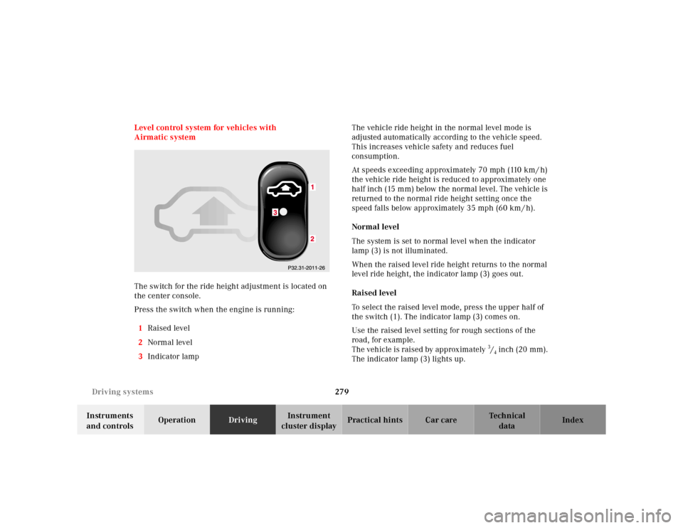
The switch for the ride height adjustment is located on
the center console.
Press the switch when the engine is running:
1Raised level
2Normal level
3Indicator lampThe vehicle ride height in the normal level mode is
adjusted automatically according to the vehicle speed.
This increases vehicle safety and reduces fuel
consumption.
At speeds exceeding approximately 70 mph (110 km / h)
the vehicle ride height is reduced to approximately one
half inch (15 mm) below the normal level. The vehicle is
returned to the normal ride height setting once the
speed falls below approximately 35 mph (60 km / h).
Normal level
The system is set to normal level when the indicator
lamp (3) is not illuminated.
When the raised level ride height returns to the normal
level ride height, the indicator lamp (3) goes out.
Raised level
To select the raised level mode, press the upper half of
the switch (1). The indicator lamp (3) comes on.
Use the raised level setting for rough sections of the
road, for example.
The vehicle is raised by approximately 3/4 inch (20 mm).
The indicator lamp (3) lights up.
Page 283 of 421
280 Driving systems
Te ch n ica l
data Instruments
and controlsOperationDrivingInstrument
cluster displayPractical hints Car care Index
The message “AIR SPRING – VEHICLE RISING” appears
in the multifunction display. The display switches off
when the vehicle is raised.
Notes:
The raised level setting switches off at speeds exceeding
approximately 75 mph (120 km / h), or if vehicle speed
is operated between 50 mph (80 km / h) and 75 mph
(120 km / h) for approximately 5 minutes. The message
“AIR SPRING – LEVEL CANCELLED” appears in the
display.
The raised level setting will be stored in memory after
the electronic key is removed from the starter switch if
you did not drive at the aforementioned speeds.
See “AIR SPRING” on page 325 for malfunction and
warning messages.Level control system for vehicles with
Active Body Control (ABC)
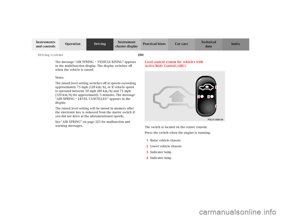
The switch is located on the center console.
Press the switch when the engine is running:
1Raise vehicle chassis
2Lower vehicle chassis
3Indicator lamp
4Indicator lamp
Page 288 of 421
285 Parking system
Te ch n ica l
data Instruments
and controlsOperationDrivingInstrument
cluster displayPractical hints Car care Index Parking assist (Parktronic)
The Parktronic system assists the driver during parking
maneuvers. It visually and audibly indicates the relative
distance between the vehicle and an obstacle.
The front area of the vehicle is monitored when driving
forward. When reversing or with the gear selector lever
in position “N”, the front as well as the rear areas are
monitored.
With the electronic key in starter switch position 2,
Parktronic engages automatically at speeds up to
approximately 10 mph (15 km / h) and deactivates
during higher speeds.
Parktronic can be switched off by a control switch
located in the center console. It engages automatically
again when starting the engine.
See page 289 for Parktronic switch.
Wa r n i n g !
Parktronic is a supplemental system. It is not
intended to nor does it replace the need for extreme
care. The responsibility during parking and other
critical maneuvers rests always with the driver.Special attention must be paid to objects having
smooth surfaces or low silhouettes (e.g. trailer
couplings, painted posts, or street curbs). Such
objects may not be detected by the system and can
damage the vehicle.The operational function of the Parktronic can be
affected by dirty sensors, especially at times of
snow and ice. See page 378 for notes on cleaning
the parktronic system sensors.Interference caused by other ultrasonic signals
(e.g. working jackhammers or the air brakes of
trucks) can cause the system to send erratic
indications, and should be taken into
consideration.
Page 290 of 421
287 Parking system
Te ch n ica l
data Instruments
and controlsOperationDrivingInstrument
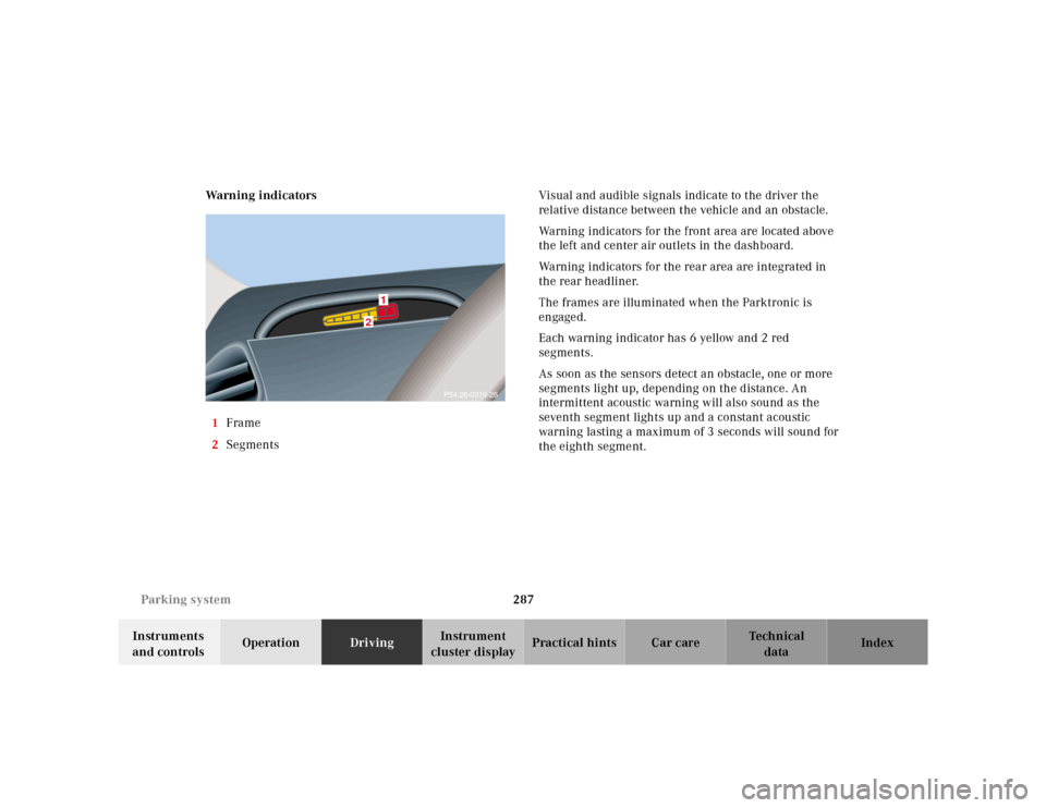
cluster displayPractical hints Car care Index Warning indicators
1Frame
2SegmentsVisual and audible signals indicate to the driver the
relative distance between the vehicle and an obstacle.
Warning indicators for the front area are located above
the left and center air outlets in the dashboard.
Warning indicators for the rear area are integrated in
the rear headliner.
The frames are illuminated when the Parktronic is
engaged.
Each warning indicator has 6 yellow and 2 red
segments.
As soon as the sensors detect an obstacle, one or more
segments light up, depending on the distance. An
intermittent acoustic warning will also sound as the
seventh segment lights up and a constant acoustic
warning lasting a maximum of 3 seconds will sound for
the eighth segment.
2
1
P54.26-0319-26
Page 293 of 421
290 What you should know at the gas station
Te ch n ica l
data Instruments
and controlsOperationDrivingInstrument
cluster displayPractical hints Car care Index
What you should know at the gas station
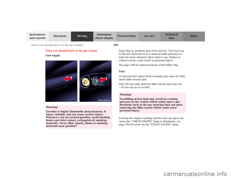
Fuel supplyOpen flap by pushing near front (arrow). Turn fuel cap
to the left and hold on to it until possible pressure in
tank has been released, then remove cap. Failure to
remove slowly could result in personal injury.
See page 368 for manual release of fuel filler flap.
Fuel
To prevent fuel vapors from escaping into open air, fully
insert filler nozzle unit.
Only fill fuel tank until the filler nozzle unit cuts out
— do not top up or overfill.
Leaving the engine running and the fuel cap open can
cause the “CHECK ENGINE” lamp to illuminate, see
page 296 for notes on the “CHECK ENGINE” lamp.
Wa r n i n g !
Gasoline is highly flammable and poisonous. It
burns violently and can cause serious injury.
Whenever you are around gasoline, avoid inhaling
fumes and skin contact, extinguish all smoking
materials. Never allow sparks, flame or smoking
materials near gasoline!
P88.60-2001-26
Wa r n i n g !
Overfilling of fuel tank may result in creating
pressure in the system which could cause a gas
discharge such as the gas spraying back out upon
removing the filler nozzle which could cause
personal injury.
Page 295 of 421
292 What you should know at the gas station
Te ch n ica l
data Instruments
and controlsOperationDrivingInstrument
cluster displayPractical hints Car care Index
Tire pressure
For tire pressure, refer to tire pressure label inside the
fuel filler flap. See page 348 for further details.
Air conditioner
R-134a refrigerant and special PAG lubricant, refer to
“Technical Data”.
Spark plugs
Approved spark plugs, refer to “Technical Data”.
Windshield cleaning
To prevent damage to the engine hood, the windshield
wipers must not be folded forward in parked position.
See page 380 for cleaning the windshield.Bulbs
High and low beams: H7 (55 W),
low beam: Xenon (optional)
fog lamps: H1 (55 W),
turn signal lamps,
front 2357 NA (28.5 / 8.3 W [Yellow]),
parking and standing lamps, front: W 5W (5 W)
side marker lamps, front: 5 W / 4 cp,
turn signal lamps, rear: 1156 NA bulb,
tail and parking lamp: P 21 / 4 W,
tail, parking and rear fog lamp, driver’s side: P 21 / 4 W,
tail, parking, standing and
side marker lamp: R 5 W / 4 cp,
backup lamps: 21 W / 32 cp,
license plate lamps: 5 W / 4 cp
Page 298 of 421
295 Contents - Instrument cluster display
Te ch n ica l
data Instruments
and controlsOperation DrivingInstrument
cluster displayPractical hints Car care Index
Instrument cluster displayMalfunction and indicator
lamps in the
instrument cluster ....................296
On-board diagnostic system .....296
Check engine malfunction
indicator lamp .............................296
Brake warning lamp ..................298
Supplemental restraint
system (SRS)
indicator lamp .............................299
Fuel reserve warning .................299
ABS malfunction
indicator lamp .............................300
Electronic stability
program (ESP) —
warning lamp ..............................301
Distronic (DTR) –
warning lamp ..............................301
Seat belt nonusage
warning lamp ..............................302Malfunction and
indicator lamp in the
center console ........................... 302
AIRBAG OFF indicator lamp .... 302
Malfunction and
warning messages in the
multifunction display .............. 303
DISPLAY DEFECTIVE ................ 304
BATTERY/ALTERNATOR .......... 305
ENTRANCE POSITION .............. 306
BRAKE ASSIST ........................... 306
BRAKE LINING WEAR .............. 307
BRAKE FLUID ............................ 307
PARKING BRAKE ....................... 308
TRUNK OPEN ............................. 308
ELEC. STABIL. PROG.
(Electronic stability
program) ..................................... 309
COOLANT (coolant level) .......... 310
COOLANT
(coolant temperature) ................ 311LIGHTING SYSTEM .................... 312
LIGHT SENSOR ........................... 314
ACTIV E BO DY CO NTROL
(ABC) ............................................ 314
TIRE PRESSURE ......................... 316
ENGINE OIL LEVEL ................... 318
CRUISE CONTROL ..................... 319
KEY ............................................... 319
DOOR ...........................................320
HOOD ...........................................320
TELE AID .....................................321
OIL TEMP.
(engine oil temperature) ...........321
CHIP-CARD (KEYLESS-GO) ......322
SELECTOR LEVER ......................323
TELEPHONE – FUNCTION .......323
WASHER FLUID .........................324
AIR SPRING (AirMatic) .............325
DISTRONIC (DTR) ......................326
Page 302 of 421
299 Malfunction and indicator lamps
Te ch n ica l
data Instruments
and controlsOperation DrivingInstrument
cluster displayPractical hints Car care Index Supplemental restraint system (SRS) indicator lamp
The operational readiness of the airbag
system is verified by the indicator lamp
“SRS” in the instrument cluster when
turning the electronic key in starter switch to position 1
or 2. If no fault is detected, the lamp will go out after
approximately 4 seconds; after the lamp goes out, the
system continues to monitor the components and
circuitry of the airbag system and will indicate a
malfunction by coming on again.
See page 94 for notes on airbags, see page 92 for belt
tensioners and page 84 for infant and child seat
restraint.Fuel reserve warning
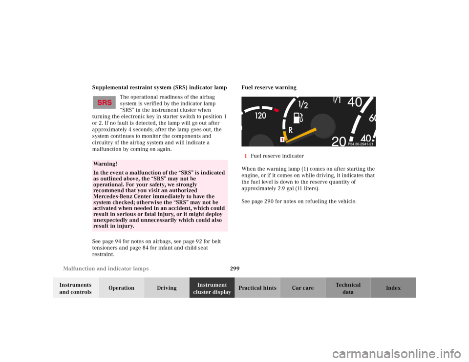
1Fuel reserve indicator
When the warning lamp (1) comes on after starting the
engine, or if it comes on while driving, it indicates that
the fuel level is down to the reserve quantity of
approximately 2.9 gal (11 liters).
See page 290 for notes on refueling the vehicle.
Wa r n i n g !
In the event a malfunction of the “SRS” is indicated
as outlined above, the “SRS” may not be
operational. For your safety, we strongly
recommend that you visit an authorized
Mercedes-Benz Center immediately to have the
system checked; otherwise the “SRS” may not be
activated when needed in an accident, which could
result in serious or fatal injury, or it might deploy
unexpectedly and unnecessarily which could also
result in injury.