Page 13 of 299
IntroductionWhere to find it
The Operator’s Manual is divided into eight sections:
• Instruments and controls: An overview of all the controls that can be operated from the driver’s seat.
• Operation: Information on the vehicle’s equipment and its operation.
•Driving: Important information on driving.
• Instrument cluster display: Displays and indicator lamps on the instrument cluster with brief instructions.
• Practical hints: Assistance and instructions in the event of an emergency.
•Car care: Instructions on caring for your vehicle.
• Technical data: All the important technical data for your vehicle as well as consumer information such as fuels,
coolants, lubricants etc. is contained here.
•Index: Key terms to help you find a topic quickly.
Other documents may also be supplied, depending on your vehicle’s equipment.
Explanation of color used:
Warning notices for the protection of yourself and
others appear on red background.
13
Page 47 of 299
Seats
Te ch n ica l
data Instruments
and controlsOperationDrivingInstrument
cluster displayPractical hints Car care Index
Storing
Three sets of seat/head restraint and exterior rear view
mirror positions may be programmed into memory.
After the seat/head restraint and exterior rear view
mirrors are positioned, push memory button (6),
release, and within 3 seconds push position button “1”.
A second and third set of positions for the same seat/
head restraint and exterior rear view mirrors can be
programmed into memory by pushing first memory
button (6) and then “2”, respectively “3”.
Note:
See page 75for instructions on adjustment of mirrors.Recalling
To recall a seat/head restraint and exterior rear view
mirror position, push and hold position button “1”, “2”
or “3” until seat/head restraint and exterior rear view
mirror movement has stopped. The seat/head restraint
and exterior rear view mirror movement stops when the
position button is released.
Caution!
Do not operate the power seats using the memory
button if the backrest is in an excessively reclined
position. Doing so could cause damage to front or rear
seats.
First move the backrest to an upright position.
47
Page 49 of 299
50 Seats
Te ch n ica l
data Instruments
and controlsOperationDrivingInstrument
cluster displayPractical hints Car care Index
Front head restraints
Removal:
Tilt the backrest rearward for easier removal of the front
head restraints.
Push button (1) up to bring the power adjustable head
restraint to its highest position.
Pull out head restraint completely with both hands.Installation:
Push button (1) of the power adjustable head restraint
up for approximately 5 seconds.
Insert the head restraint and push it down to the stop.
Adjust head restraint to the desired position.
For positioning of head restraints see also power seats,
front on page
44
and head restraints, rear on page .
Warning!
For your protection, drive only with properly
positioned head restraints.Adjust head restraint to support the back of the
head approximately at ear level.Do not drive the vehicle without the seat head
restraints. Head restraints are intended to help
reduce injuries during an accident.
49
Page 51 of 299
Seats
Te ch n ica l
data Instruments
and controlsOperationDrivingInstrument
cluster displayPractical hints Car care Index Backrest
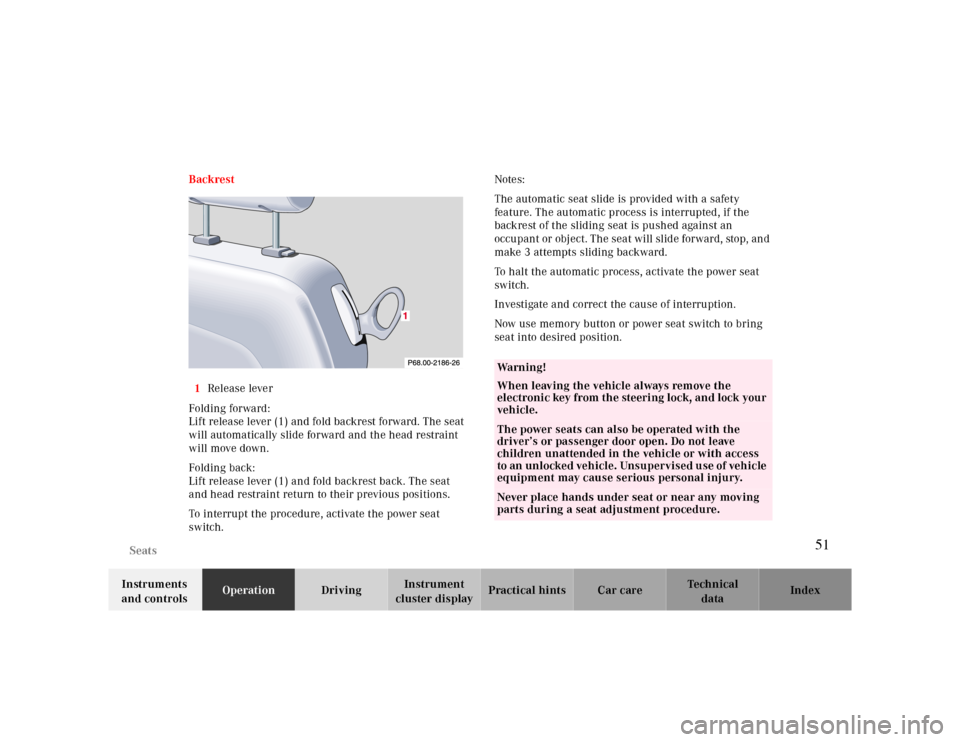
1Release lever
Folding forward:
Lift release lever (1) and fold backrest forward. The seat
will automatically slide forward and the head restraint
will move down.
Folding back:
Lift release lever (1) and fold backrest back. The seat
and head restraint return to their previous positions.
To interrupt the procedure, activate the power seat
switch.Notes:
The automatic seat slide is provided with a safety
feature. The automatic process is interrupted, if the
backrest of the sliding seat is pushed against an
occupant or object. The seat will slide forward, stop, and
make 3 attempts sliding backward.
To halt the automatic process, activate the power seat
switch.
Investigate and correct the cause of interruption.
Now use memory button or power seat switch to bring
seat into desired position.
Wa r n i n g !
When leaving the vehicle always remove the
electronic key from the steering lock, and lock your
vehicle.The power seats can also be operated with the
driver’s or passenger door open. Do not leave
children unattended in the vehicle or with access
to an unlocked vehicle. Unsupervised use of vehicle
equipment may cause serious personal injury.Never place hands under seat or near any moving
parts during a seat adjustment procedure.
51
Page 59 of 299
Restraint systems
Te ch n ica l
data Instruments
and controlsOperationDrivingInstrument
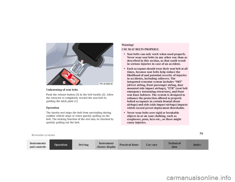
cluster displayPractical hints Car care Index Unfastening of seat belts
Push the release button (3) in the belt buckle (2). Allow
the retractor to completely rewind the seat belt by
guiding the latch plate (1).
Operation
The inertia reel stops the belt from unwinding during
sudden vehicle stops or when quickly pulling on the
belt. The locking function of the reel may be checked by
quickly pulling out the belt.
1
2
3
Wa r n i n g !
USE SEAT BELTS PROPERLY.• Seat belts can only work when used properly.
Never wear seat belts in any other way than as
described in this section, as that could result
in serious injuries in case of an accident.• Each occupant should wear their seat belt at all
times, because seat belts help reduce the
likelihood of and potential severity of injuries
in accidents, including rollovers. The
integrated restraint system includes “SRS”
(driver airbag, front passenger airbag, door
mounted side impact airbags), “ETR” (seat belt
emergency tensioning retractors), and front
seat knee bolsters. The system is designed to
enhance the protection offered to properly
belted occupants in certain frontal (front
airbags) and side (side impact airbags) impacts
which exceed preset deployment thresholds. • Never wear belts over rigid or breakable
objects in or on your clothing, such as
eyeglasses, pens, keys etc., as these might
cause injuries.
59
Page 72 of 299
Restraint systems
Te ch n ica l
data Instruments
and controlsOperationDrivingInstrument
cluster displayPractical hints Car care Index
Installation of infant and child restraint systems
This vehicle is provided with tether anchorages for a top
tether strap at each of the rear seats.
To secure a tether strap to the anchorage, securely
fasten the hook (3), which is part of the tether strap, to
the anchorage ring (2).
Children too big for child restraint systems must
ride in back seats using regular seat belts. Position
shoulder belt across chest and shoulder, not face or
neck. A booster seat may be necessary to achieve
proper belt positioning for children from 41 lbs. to
the point where a lap/shoulder belt fits properly
without one.When the child restraint is not in use, remove it
from the vehicle or secure it with the seat belt to
prevent the child restraint from becoming a
projectile in the event of an accident.
72
Page 73 of 299
Adjusting telescoping steering column
Te ch n ica l
data Instruments
and controlsOperationDrivingInstrument
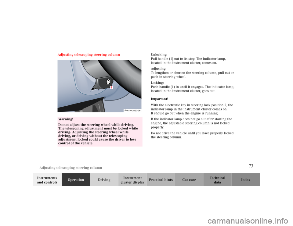
cluster displayPractical hints Car care Index Adjusting telescoping steering columnUnlocking :
Pull handle (1) out to its stop. The indicator lamp,
located in the instrument cluster, comes on.
Ad justing:
To lengthen or shorten the steering column, pull out or
push in steering wheel.
Locking:
Push handle (1) in until it engages. The indicator lamp,
located in the instrument cluster, goes out.
Important!
With the electronic key in steering lock position 2, the
indicator lamp in the instrument cluster comes on.
It should go out when the engine is running.
If the indicator lamp does not go out after starting the
engine, the adjustable steering column is not locked
properly.
Do not drive the vehicle until you have properly locked
the steering column.
Warning!
Do not adjust the steering wheel while driving.
The telescoping adjustment must be locked while
driving. Adjusting the steering wheel while
driving, or driving without the telescoping
adjustment locked could cause the driver to lose
control of the vehicle.
1
P46.10-2020-26
73
Page 82 of 299
Instrument cluster
Te ch n ica l
data Instruments
and controlsOperationDrivingInstrument
cluster displayPractical hints Car care Index
Coolant temperature gauge (3)
During severe operating conditions and stop-and-go city
traffic, the coolant temperature may rise close to the red
marking.
The engine should not be operated with the coolant
temperature in the red zone. Doing so may cause
serious engine damage which is not covered by the
Mercedes-Benz Limited Warranty.Outside temperature indicator (5)
The temperature sensor is located in the front bumper
area. Due to its location, the sensor can be affected by
road or engine heat during idling or slow driving. This
means that the accuracy of the displayed temperature
can only be verified by comparison to a thermometer
placed next to the sensor, not by comparison to external
displays (e.g. bank signs etc.).
Adaptation to ambient temperature takes place in steps
and depends on the prevailing driving conditions (stop-
and-go or moderate, constant driving) and amount of
temperature change.
Warning!
• Driving when your engine is badly overheated
can cause some fluids which may have leaked
into the engine compartment to catch fire. You
could be seriously burned.• Steam from an overheated engine can cause
serious burns and can occur just by opening
the engine hood. Stay away from the engine if
you see or hear steam coming from it.Turn off the engine, get out of the vehicle and do
not stand near the vehicle until it cools down.
Wa r n i n g !
The outside temperature indicator is not designed
to serve as an Ice-Warning Device and is therefore
unsuitable for that purpose. Indicated
temperatures just above the freezing point do not
guarantee that the road surface is free of ice.
82