2000 MERCEDES-BENZ CLK CABRIOLET check engine light
[x] Cancel search: check engine lightPage 4 of 323

Operation Audio and telephone 125 The first 1 000 miles (1 500 km) 171 Travelling abroad 200
Power windows 143 Maintenance 171 Cruise control 201
Interior lighting 146 Catalytic converter 172 Brake assist system (BAS) 204
Entrance lamps, exit lamps in doors 146 Emission control 173 Antilock brake system (ABS) 206
Sun visors 147 Tele Aid 174
Electronic stability program (ESP)
208
Illuminated vanity mirrors 147 Steering lock 180 What you should know at the
Interior 148 Starting and turning off the engine 182 gas station 211
Storage compartments, armrest and
cup holder148 Automatic transmission 183 Check regularly and before a
long trip 213
Glove box 148 Parking brake 192
Ashtray 150 Driving instructions 192
Instrument cluster display
Lighter 151 Drive sensibly – save fuel 192 Malfunction and indicator
lamps in the instrument cluster 216
Cargo tie down rings 152 Drinking and driving 193 On-board diagnostic system
Parcel net in front passenger footwell 152 Pedals 193 Check engine malfunction
indicator lamp 216
Armrest, rear bench 152 Power assistance 193 Supplemental restraint system
(SRS) indicator lamp 218
Telephone, general 153 Brakes 193 Fuel reserve and fuel cap
Cellular telephone 153 Driving off 194 placement warning 218
Garage door opener 154 Parking 195 Electronic stability
program(ESP) — warning lamp 219
Soft top 158 Tires 195
BAS/ESP malfunction indicator
lamp
219
Wind screen 165 Snow chains 198
ABS malfunction indicator lamp
219
Winter driving instructions 198 Telescoping steering column –
indicator lamp220
DrivingDeep water 199 Seat belt warning lamp 220
Control and operation of radio transmitters
170 Passenger compartment 200
4
Page 5 of 323

Malfunction and indicator lamps in the
center console 221Practical hintsJump starting 263
AIRBAG OFF indicator lamp 221 First aid kit 238 Towing the vehicle 265
Roll bar warning lamp 221 Shelf below rear window 238 Transmission selector lever,
manually unlocking 268
Malfunction and warning messages in
the multifunction display 222Stowing things in the vehicle 238 Bulbs 269
DISPLAY DEFECTIVE (engine
control unit) 223Luggage cover 238 Adjusting headlamp aim 274
DISPLAY DEFECTIVE (several
systems) 223Spare wheel, vehicle tools, storage
compartment 240Changing batteries in the
electronic main key 277
BATTERY/ALTERNATOR 224 Vehicle jack 241 Raising soft top manually 280
ABS-SYSTEM 225 Fuses 242 Antenna 287
BRAKE ASSIST 225 Hood 244 Manual release for fuel filler
BRAKE LINING WEAR 226 Checking engine oil level 246 flap 287
BRAKE FLUID 226 Automatic transmission fluid level 247 Trunk lamp 288
PARKING BRAKE 227 Coolant level 247 Replacing wiper blade insert 288
ENGINE FAN 227 Adding coolant 248
COOLANT (coolant level) 228
Windshield washer / headlamp clean.system
249
Vehicle care
COOLANT TEMP. (coolant
temperature) 229Windshield and headlamp washer fluid
mixing ratio 249Cleaning and care of the vehicle 292
LIGHTING SYSTEM 230 Wheels 250 Engine cleaning 293
LIGHT SENSOR 231 Tire replacement 250 Vehicle washing 293
STEER. WHEEL ADJUST. 231 Rotating wheels 251 Power washer 293
OIL TEMP. 232 Spare wheel 252 Plastic and rubber parts 293
ENGINE OIL LEVEL 232 Changing wheels 254 Tar stains 294
ELEC. STABIL. PROG. (Electronic
stability program) 234Tire inflation pressure 259 Window cleaning 294
WASHER FLUID 235 Battery 261
5
Page 27 of 323

Central locking system
Te ch n ica l
data Instruments
and controlsOperationDrivingInstrument
cluster displayPractical hints Car care Index Start lock-out
Important!
Removing the electronic key from the steering lock
activates the start lock-out. The engine cannot be
started.
Inserting the electronic key in the steering lock
deactivates the start lock-out.
Note:
In case the engine cannot be started (vehicle’s battery is
in order), the system is not operational. Contact an
authorized Mercedes-Benz Center or call 1-800-FOR-
MERCedes (in the USA) or 1-800-387-0100 (in Canada).General notes on the central locking system
If the electronic key is inserted in the steering lock, the
vehicle cannot be locked or unlocked with the remote
control.
If the vehicle cannot be locked or unlocked:
•Aim transmitter eye at a receiver of either door
handle. Check the batteries of the electronic main
key, see page 288, or synchronize the remote
control, see page 290.
•Use the mechanical key to unlock the driver’s door.
To start the engine, insert the electronic main key in
the steering lock. There could be a slight delay until
the electronic main key can be turned in the
steering lock.
27
Page 213 of 323

Check regularly and before a long trip
Te ch n ica l
data Instruments
and controlsOperationDrivingInstrument
cluster displayPractical hints Car care Index
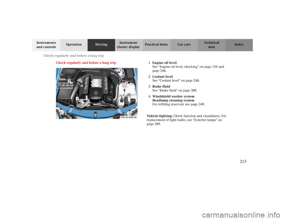
Check regularly and before a long trip 1Engine oil level
See “Engine oil level, checking” on page110and
page246.
2Coolant level
See “Coolant level” on page248.
3Brake fluid
See “Brake fluid” on page309.
4Windshield washer system
Headlamp cleaning system
For refilling reservoir see page249.
Ve h i c l e l i g h t i n g : Check function and cleanliness. For
replacement of light bulbs, see “Exterior lamps” on
page269.
213
Page 215 of 323

Instrument cluster display
Malfunction and warning messages in the
multifunction display 222
Malfunction and indicator lamps in the instrument cluster 216 DISPLAY DEFECTIVE (engine control unit) 223
On-board diagnostic system DISPLAY DEFECTIVE (several systems) 223
Check engine malfunction indicator lamp 216 BATTERY/ALTERNATOR 224
Supplemental restraint system (SRS) indicator lamp 218 ABS-SYSTEM 225
Fuel reserve and fuel cap BRAKE ASSIST 225
placement warning 218 BRAKE LINING WEAR 226
Electronic stability program(ESP) — warning lamp 219 BRAKE FLUID 226
BAS/ESP malfunction indicator lamp
219 PARKING BRAKE 227
ABS malfunction indicator lamp
219 ENGINE FAN 227
Telescoping steering column – indicator lamp 220 COOLANT (coolant level) 228
Seat belt warning lamp 220 COOLANT TEMP. (coolant temperature) 229
Malfunction and indicator lamps in the center console 221 LIGHTING SYSTEM 230
AIRBAG OFF indicator lamp 221 LIGHT SENSOR 231
Roll bar warning lamp 221 STEER. WHEEL ADJUST. 231
OIL TEMP. 232
ENGINE OIL LEVEL 232
ELEC. STABIL. PROG. (Electronic stability
program) 234
WASHER FLUID 235
215
Page 219 of 323

Malfunction and indicator lamps
Te ch n ica l
data Instruments
and controlsOperation DrivingInstrument
cluster displayPractical hints Car care Index Electronic stability program (ESP) — warning lamp
The yellow ESP warning lamp in the
speedometer dial comes on with the
electronic key in steering lock position 2.
It should go out with engine running.
See page208if the warning lamp lights up or flashes
when the vehicle is moving.
BAS / ESP malfunction indicator lamp
The malfunction indicator lamp for the ESP
is combined with that of the BAS.
The yellow BAS/ESP malfunction indicator
lamp in the instrument cluster comes on with the
electronic key in steering lock position 2. It should go
out with the engine running.
If the BAS/ESP malfunction indicator lamp remains
illuminated with the engine running, see page209
.ABS malfunction indicator lamp
The ABS malfunction indicator lamp in the
instrument cluster comes on with the
electronic key in steering lock position 2 and
should go out with the engine running.
When the ABS malfunction indicator lamp symbol and
warning in the instrument cluster remains illuminated
while the engine is running, it indicates that the ABS
has detected a malfunction and has switched off. In this
case, the brake system functions in the usual manner,
but without antilock assistance.
With the ABS malfunctioning, the BAS and ESP are also
switched off. Both malfunction indicator lamps come on
with the engine running.
If the charging voltage falls below 10 volts, the
malfunction indicator lamp comes on and the ABS is
switched off. When the voltage is above this value again,
the malfunction indicator lamp should go out and the
ABS is operational.
Have the system checked at your authorized
Mercedes-Benz Center as soon as possible.
See page206 for notes on the antilock brake system
(ABS).
BAS
ESP
ABS
219
Page 221 of 323

Malfunction and indicator lamps
Te ch n ica l
data Instruments
and controlsOperation DrivingInstrument
cluster displayPractical hints Car care Index Malfunction and indicator lamps in the
center console
AIRBAG OFF indicator lamp
The 7 indicator lamp will light up for approx.
6 seconds when you turn the electronic key in steering
lock to position 1 or 2.
The 7 indicator lamp stays lit as long as a
BabySmart
TM compatible child seat is properly installed
on the front passenger seat. It indicates that the front
passenger airbag is switched off.
See page63 for BabySmart
TM deactivation system.
BabySmart
TM is a trademark of Siemens Automotive Corp.
Roll bar warning lamp
The roll bar warning lamp is located in the roll bar
switch in the center console. Roll bar switch see
page 52.
With the electronic key in steering lock position 2, the
roll bar warning lamp comes on and should go out with
the engine running.
With the engine running and the roll bar lowered, the
warning lamp in the roll bar switch will blink for
approx. 15 seconds. The blinking is reminding you to
raise the roll bar if the rear passenger seats are
occupied.
Note:
Have the roll bar system checked at your authorized
Mercedes-Benz Center as soon as possible.Wa r n i n g !
If the warning lamp does not go out after starting
the engine, or if it comes on while driving, then the
roll bar system is not operating properly and may
not activate in an accident. In this case, raise the
roll bar manually (see page51) before continuing
to drive.
221
Page 230 of 323

Malfunction and warning messages
Te ch n ica l
data Instruments
and controlsOperation DrivingInstrument
cluster displayPractical hints Car care Index
LIGHTING SYSTEMWhen the message appears after starting the engine, or
if it comes on while driving, this indicates a failure in
the parking lamp, taillamp, stop lamp, or low beam
headlamp. See page 269 for instructions on replacing
bulbs.
If an exterior lamp fails, the message will appear only
when that lamp is switched on.
If a brake lamp fails, the message will appear when
applying the brake and stays on until the engine is
turned off.
Note:
If additional lighting is installed (e.g. auxiliary
headlamps etc.) be certain to connect into the fuse
before the failure indicator monitoring unit order to
avoid damaging the system.
Line 1 Line 2
LAMP DEFECTIVE CHECK LAMPS!
DISPLAY DEFECTIVE VISIT WORKSHOP!
2 C*
* C = Category, see page 2222
230