Page 53 of 224

²Station overload.Weak signals are sometimes captured by stronger
signals when you pass a broadcast tower. A stronger signal may
temporarily overtake a weaker signal and play while the weak station
frequency is displayed.
The audio system automatically switches to single channel reception if it
will improve the reception of a station normally received in stereo.
Audio system warranties and service
Refer to the ªWarranty Guideº for audio system warranty information.
If service is necessary, see your dealer or a qualified technician.
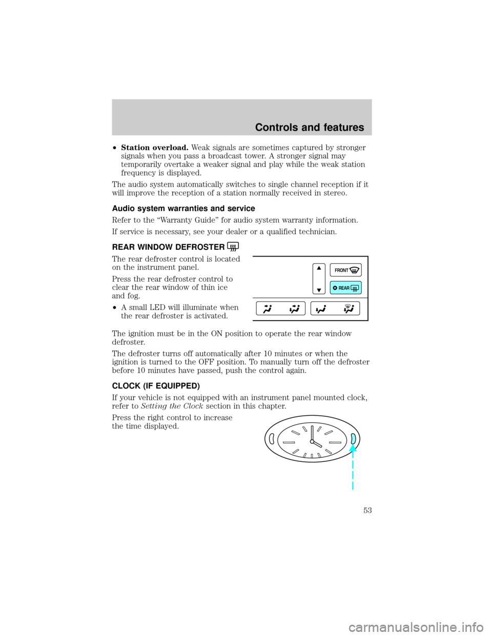
REAR WINDOW DEFROSTER
The rear defroster control is located
on the instrument panel.
Press the rear defroster control to
clear the rear window of thin ice
and fog.
²A small LED will illuminate when
the rear defroster is activated.
The ignition must be in the ON position to operate the rear window
defroster.
The defroster turns off automatically after 10 minutes or when the
ignition is turned to the OFF position. To manually turn off the defroster
before 10 minutes have passed, push the control again.
CLOCK (IF EQUIPPED)
If your vehicle is not equipped with an instrument panel mounted clock,
refer toSetting the Clocksection in this chapter.
Press the right control to increase
the time displayed.
FRONT
REAR
Controls and features
53
Page 54 of 224
Press the left control to decrease
the time displayed.
AUXILIARY POWER POINT
The auxiliary power point is located
under the instrument panel. This
outlet should be used in place of the
cigarette lighter for optional
electrical accessories.
POSITIONS OF THE IGNITION
1. ACCESSORY, allows the electrical
accessories such as the radio to
operate while the engine is not
running.
2. LOCK, locks the steering wheel,
automatic transmission gearshift
lever and allows key removal.
3. OFF, shuts off the engine and all
accessories without locking the
steering wheel.
4. ON, all electrical circuits operational. Warning lights illuminated. Key
position when driving.
5. START, cranks the engine. Release the key as soon as the engine
starts.
VOL
PUSH ONTAPE
MUTESEEK
TUNE
AM
FM
REW
FFSIDE 1 2
COMP
SHUFFCDEJ
RDS
SCAN AUTO123
4
56
BASS
TREBSELBAL
FADE
EXT
OFFMAX
A/CAUTOFRONT
REARSELECTRESET
3
1
2
5
4
Controls and features
54
Page 65 of 224

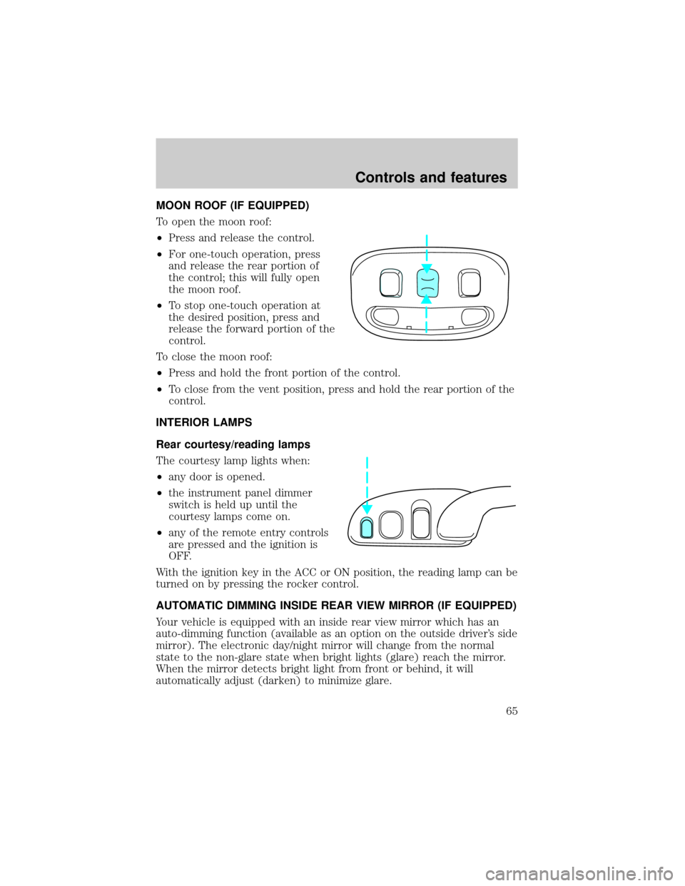
MOON ROOF (IF EQUIPPED)
To open the moon roof:
²Press and release the control.
²For one-touch operation, press
and release the rear portion of
the control; this will fully open
the moon roof.
²To stop one-touch operation at
the desired position, press and
release the forward portion of the
control.
To close the moon roof:
²Press and hold the front portion of the control.
²To close from the vent position, press and hold the rear portion of the
control.
INTERIOR LAMPS
Rear courtesy/reading lamps
The courtesy lamp lights when:
²any door is opened.
²the instrument panel dimmer
switch is held up until the
courtesy lamps come on.
²any of the remote entry controls
are pressed and the ignition is
OFF.
With the ignition key in the ACC or ON position, the reading lamp can be
turned on by pressing the rocker control.
AUTOMATIC DIMMING INSIDE REAR VIEW MIRROR (IF EQUIPPED)
Your vehicle is equipped with an inside rear view mirror which has an
auto-dimming function (available as an option on the outside driver's side
mirror). The electronic day/night mirror will change from the normal
state to the non-glare state when bright lights (glare) reach the mirror.
When the mirror detects bright light from front or behind, it will
automatically adjust (darken) to minimize glare.
Controls and features
65
Page 82 of 224

Procedure to program spare SecuriLockYkeys to your vehicle
New coded keys must have the correct mechanical key cut for your
vehicle.
Conventional (non-coded) keyscannotbe programmed to your vehicle.
You will need to have two previously programmed coded keys and the
new unprogrammed SecuriLockykey readily accessible for timely
implementation of each step in the procedure. Please read and
understand the entire procedure before you begin.
1. Insert the first previously programmed coded key into the ignition and
turn the ignition from OFF to ON (maintain ignition in ON for at least
one second).
2. Turn ignition to OFF and remove the first coded key from the ignition.
3. Within five seconds of turning the ignition to OFF, insert the second
previously programmed coded key into the ignition and turn the ignition
from OFF to ON (maintain ignition in ON for at least one second but no
more than five seconds).
4. Turn the ignition to OFF and remove the second coded key from the
ignition.
5. Within 10 seconds of turning the ignition to OFF, insert the new
unprogrammed key (new key/valet key) into the ignition and turn the
ignition from OFF to ON (maintain ignition in ON for at least one
second). This step will program your new key to a coded key.
6. To program additional new unprogrammed key(s), repeat this
procedure from step 1.
If the programming procedure was successful, the new coded key(s) will
start the vehicle's engine. The theft indicator (located on the instrument
panel) will light for three seconds and then go out.
If the programming procedure was not successful, the new coded key(s)
will not operate the vehicle's engine. The theft indicator will flash on and
off. Wait at least one minute and then repeat the procedure from step 1.
If failure repeats, bring your vehicle to your dealership to have the new
spare key(s) programmed.
Controls and features
82
Page 136 of 224
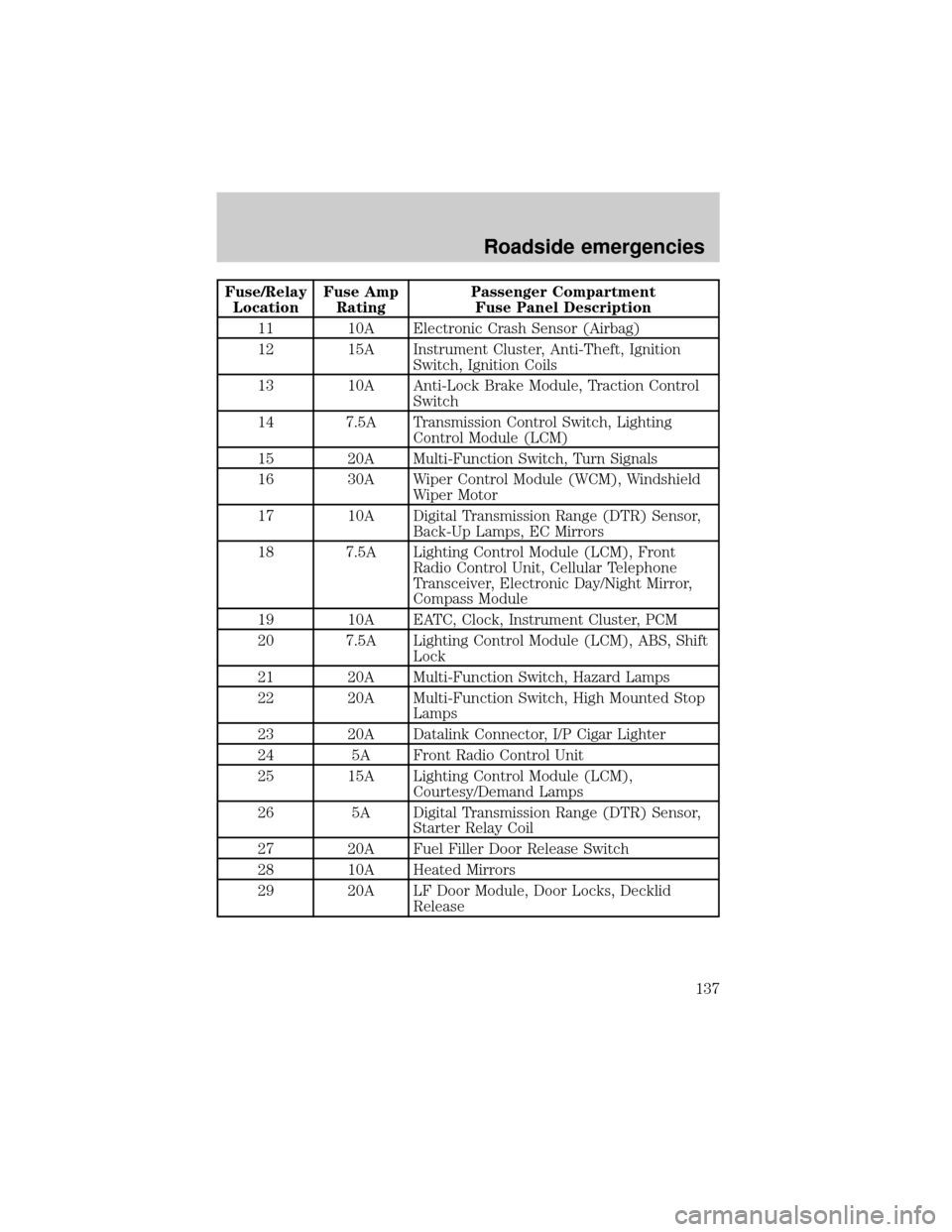
The fuses are coded as follows.
Fuse/Relay
LocationFuse Amp
RatingPassenger Compartment
Fuse Panel Description
1 10A Lighting Control Module (LCM), Left-Hand
Low Beam Headlamp
2 30A EATC Blower Motor
3 10A Lighting Control Module (LCM),
Right-Hand Low Beam Headlamp
4 7.5A Instrument Cluster
5 7.5A Lighting Control Module (LCM), Park/Tail
Lamps
6 15A EATC, Heated Seats
7 15A Lighting Control Module (LCM), Day/Night
Sensor/Amplifier
8 10A Shift Lock, Speed Control, Air Suspension,
Steering Wheel Rotation Sensor
9 20A Lighting Control Module (LCM),
Multi-Function Switch, Hi Beam
Headlamps
10 20A Brake Pedal Position (BPP) Switch, Brake
Pressure Switch, Stop Lamps
27 25
26 2423 21
2219
20
18 16
17 1514 12
1310
33
31
2932
30
28 11
97
8653
41
2RELAY
1
Roadside emergencies
136
Page 137 of 224

Fuse/Relay
LocationFuse Amp
RatingPassenger Compartment
Fuse Panel Description
11 10A Electronic Crash Sensor (Airbag)
12 15A Instrument Cluster, Anti-Theft, Ignition
Switch, Ignition Coils
13 10A Anti-Lock Brake Module, Traction Control
Switch
14 7.5A Transmission Control Switch, Lighting
Control Module (LCM)
15 20A Multi-Function Switch, Turn Signals
16 30A Wiper Control Module (WCM), Windshield
Wiper Motor
17 10A Digital Transmission Range (DTR) Sensor,
Back-Up Lamps, EC Mirrors
18 7.5A Lighting Control Module (LCM), Front
Radio Control Unit, Cellular Telephone
Transceiver, Electronic Day/Night Mirror,
Compass Module
19 10A EATC, Clock, Instrument Cluster, PCM
20 7.5A Lighting Control Module (LCM), ABS, Shift
Lock
21 20A Multi-Function Switch, Hazard Lamps
22 20A Multi-Function Switch, High Mounted Stop
Lamps
23 20A Datalink Connector, I/P Cigar Lighter
24 5A Front Radio Control Unit
25 15A Lighting Control Module (LCM),
Courtesy/Demand Lamps
26 5A Digital Transmission Range (DTR) Sensor,
Starter Relay Coil
27 20A Fuel Filler Door Release Switch
28 10A Heated Mirrors
29 20A LF Door Module, Door Locks, Decklid
Release
Roadside emergencies
137
Page 151 of 224
Working with the engine off
1. Set the parking brake and ensure the gearshift is securely latched in P
(Park).
2. Turn off the engine and remove the key.
3. Block the wheels to prevent the vehicle from moving unexpectedly.
Working with the engine on
1. Set the parking brake and ensure the gearshift is securely latched in P
(Park).
2. Block the wheels to prevent the vehicle from moving unexpectedly.
Do not start your engine with the air cleaner removed and do
not remove it while the engine is running.
OPENING THE HOOD
1. Inside the vehicle, pull the hood
release handle located under the
instrument panel.
2. Go to the front of the vehicle and
release the auxiliary latch that is
located under the front of the hood.
3. Lift the hood until the lift
cylinders hold it open.
HOOD
Maintenance and care
151
Page 188 of 224

Replacing the interior bulbs
Check the operation of the following interior bulbs frequently:
²interior overhead lamp
²map lamp
For bulb replacement, see a dealer or qualified technician.
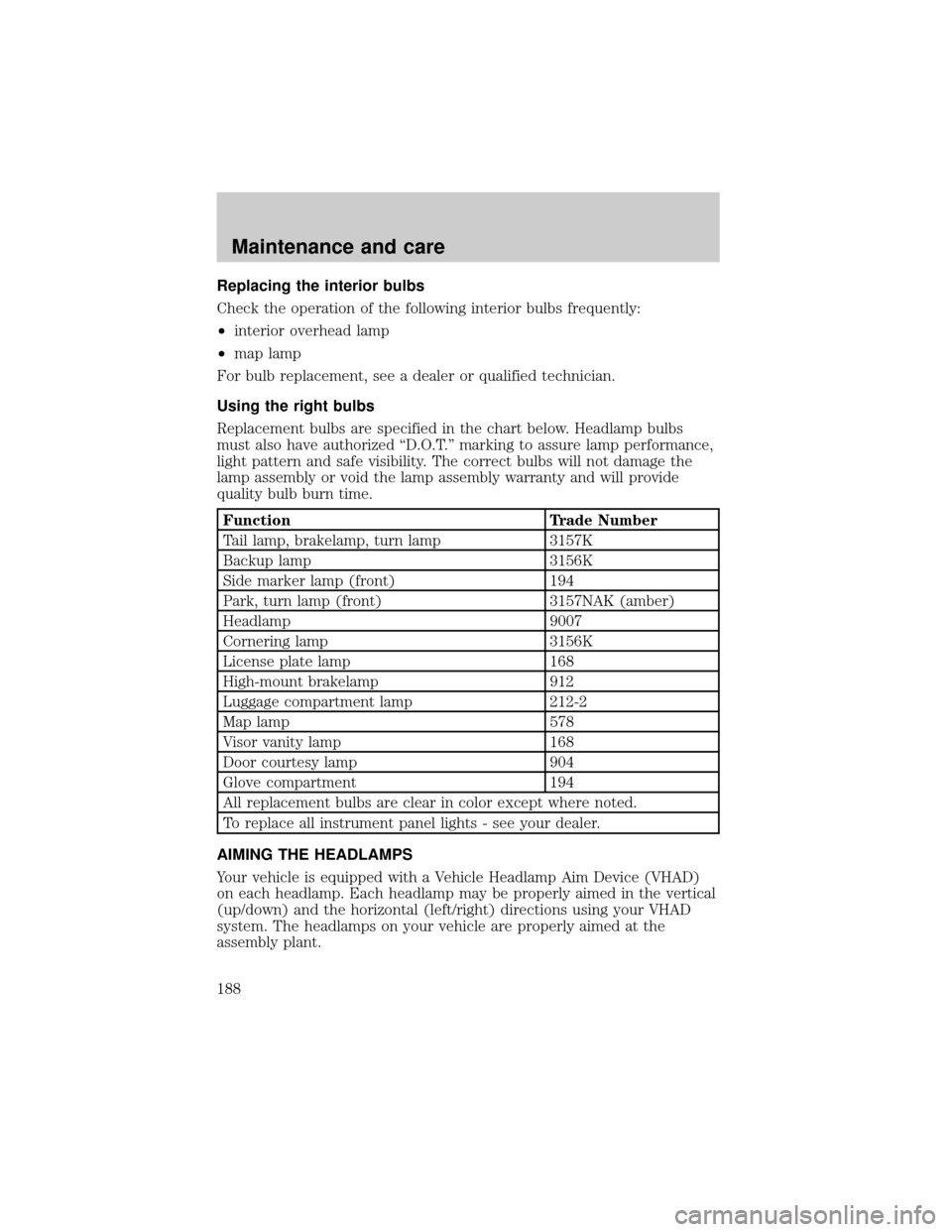
Using the right bulbs
Replacement bulbs are specified in the chart below. Headlamp bulbs
must also have authorized ªD.O.T.º marking to assure lamp performance,
light pattern and safe visibility. The correct bulbs will not damage the
lamp assembly or void the lamp assembly warranty and will provide
quality bulb burn time.
Function Trade Number
Tail lamp, brakelamp, turn lamp 3157K
Backup lamp 3156K
Side marker lamp (front) 194
Park, turn lamp (front) 3157NAK (amber)
Headlamp 9007
Cornering lamp 3156K
License plate lamp 168
High-mount brakelamp 912
Luggage compartment lamp 212-2
Map lamp 578
Visor vanity lamp 168
Door courtesy lamp 904
Glove compartment 194
All replacement bulbs are clear in color except where noted.
To replace all instrument panel lights - see your dealer.
AIMING THE HEADLAMPS
Your vehicle is equipped with a Vehicle Headlamp Aim Device (VHAD)
on each headlamp. Each headlamp may be properly aimed in the vertical
(up/down) and the horizontal (left/right) directions using your VHAD
system. The headlamps on your vehicle are properly aimed at the
assembly plant.
Maintenance and care
188