2000 LINCOLN LS relay
[x] Cancel search: relayPage 91 of 272

There may be charges incurred for certain services.
Upon receiving an Emergency Activation (by pressing the emergency
control or via an air bag activation) the Lincoln Security Response
Center relays details of the situation and the location of the vehicle to
the appropriate authorities and establishes a three-way phone call. While
the appropriate authorities dispatch help to your location, the response
center will:
²dispatch the emergency help to your location.
²when appropriate, stay in direct phone contact with you until
emergency help arrives.
²notify pre-designated family contacts or friends of the emergency
situation, if requested, or if no response is received from the vehicle.
If you are certain of your location, a direct phone call to 911 or
other emergency services may provide a faster response.
If roadside assistance is required, the Lincoln Security Response Center
will contact the Lincoln Commitment Roadside Assistance provider via
three±way phone call.
Activation and deactivation
When either of the two Lincoln RESCU controls are pressed, or the air
bags are deployed (this will activate the system as an emergency
automatically) status messages will be displayed on the vehicle's message
center, confirming an assistance request has been made.
The system can be activated whenever your ignition key is in the
RUN/START position and for six minutes after your vehicle is turned off.
Once a RESCU control has been pressed, do not attempt to crank the
engine as this may cancel the activation. In most situations, the
assistance request can only be terminated and the system reset when a
special tone is sent to the vehicle by the Lincoln Security Response
Center. (SeeAutomatic rediallater in this chapter for exceptions.)
Operation will continue even if the vehicle is turned off during an
activation (although visual feedback via the message center will not be
available in this situation).
INFO activations can be cancelled by pressing the END button on the
cellular phone.
Controls and features
91
Page 94 of 272

constellation of 24 orbiting satellites located more than 20 000 km
(12 428 miles) above the earth. At any given time, several of the 24
satellites should be visible to the vehicle's GPS receiver. Based on the
time for signals emitted by these satellites to reach the receiver, an
on-board computer will determine the vehicle's location, typically within
30 meters (100 feet). In addition to latitude and longitude, the system
also determines heading and speed.
Vehicle positioning information is relayed to the Lincoln Security
Response Center only during roadside or emergency requests. The
response center will not be able to track your location while in an
inactive state.
Lincoln RESCU system limitations
²Inoperative if cellular phone inactive or inoperative
Lincoln RESCU utilizes your vehicle's cellular phone and will not operate
if cellular service has not been activated or if the phone is inoperative.
²
Inoperative if battery discharged or disconnected
Lincoln RESCU is powered by the vehicle's battery and will not operate if
the battery is discharged or disconnected.
²
Inoperative if cellular phone is not installed in the vehicle
interface
Lincoln RESCU utilizes your vehicle's cellular phone and will not operate
if cellular phone is not installed in the vehicle interface.
²
Potentially inoperative if vehicle involved in accident
If the vehicle is involved in an accident, some components can be
damaged, rendering your RESCU System inoperative.
²
Positioning capability degraded if satellite signals obstructed
Vehicle positioning is accomplished by receiving and interpreting signals
transmitted by satellites. If the signals are obstructed positioning
capability could be degraded or lost. This situation will be most prevalent
in urban areas populated with tall buildings. tunnels, underpasses,
parking garages, trees and similar structures could also adversely affect
positioning performance. Under these conditions, the system will operate
but the response center could have difficulty identifying your current
location. (The last valid position obtained before the obstruction is
retained, however, and will be sent.) The operator may depend on you to
provide verbal information regarding vehicle location.
Controls and features
94
Page 156 of 272

If you cannot move the gearshift lever out of P (Park) with ignition in
the RUN position and the brake pedal depressed:
1. Apply the parking brake, turn ignition key to LOCK, then remove the
key.
2. Insert the key and turn it to OFF. Apply the brake pedal and shift to N
(Neutral).
3. Start the vehicle.
If it is necessary to use the above procedure to move the gearshift lever,
it is possible that a fuse has blown or the vehicle's brakelamps are not
operating properly. Refer toFuses and relaysin theRoadside
emergencieschapter.
Do not drive your vehicle until you verify that the brakelamps
are working.
If your vehicle gets stuck in mud or snow it may be rocked out by
shifting from forward and reverse gears, stopping between shifts, in a
steady pattern. Press lightly on the accelerator in each gear.
Do not rock the vehicle if the engine is not at normal operating
temperature or damage to the transmission may occur.
Do not rock the vehicle for more than a few minutes or damage
to the transmission and tires may occur or the engine may
overheat.
Always set the parking brake fully and make sure the gearshift is
latched in P (Park). Turn off the ignition whenever you leave
your vehicle.
If the parking brake is fully released, but the brake warning lamp
remains illuminated, the brakes may not be working properly.
See your dealer or a qualified service technician.
Driving with a 5±speed automatic transmission (if equipped)
Understanding gearshift positions
Pull the gearshift lever towards you and downward to the desired gear.
The gearshift positions are displayed on the floor console next to the
gearshift lever and on the instrument cluster.
Driving
156
Page 175 of 272

The fuel pump shut-off switch is
located in the driver's foot well,
behind the kick panel. The reset
button for the fuel pump shut-off
switch is accessible through an
opening in the kick panel.
Use the following procedure to reset the fuel pump shut-off switch.
1. Turn the ignition to the OFF position.
2. Check the fuel system for leaks.
3. If no fuel leak is apparent, reset the fuel pump shut-off switch by
pushing in on the reset button.
4. Turn the ignition to the RUN position. Pause for a few seconds and
return the key to the OFF position.
5. Make a further check for leaks in the fuel system.
FUSES AND RELAYS
Fuses
If electrical components in the
vehicle are not working, a fuse may
have blown. Blown fuses are
identified by a broken wire within
the fuse. Check the appropriate
fuses before replacing any electrical
components.
15
Roadside emergencies
175
Page 177 of 272

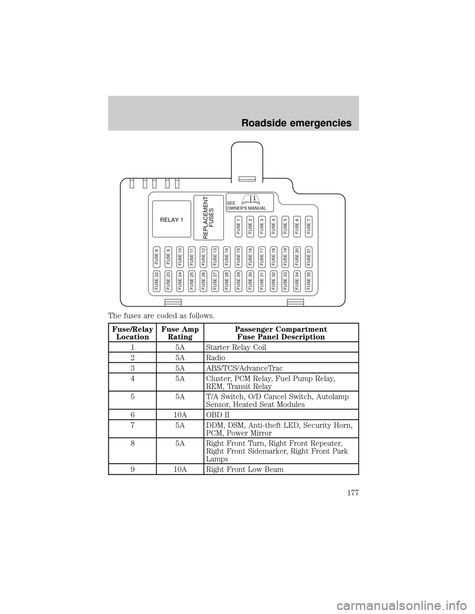
The fuses are coded as follows.
Fuse/Relay
LocationFuse Amp
RatingPassenger Compartment
Fuse Panel Description
1 5A Starter Relay Coil
2 5A Radio
3 5A ABS/TCS/AdvanceTrac
4 5A Cluster, PCM Relay, Fuel Pump Relay,
REM, Transit Relay
5 5A T/A Switch, O/D Cancel Switch, Autolamp
Sensor, Heated Seat Modules
6 10A OBD II
7 5A DDM, DSM, Anti-theft LED, Security Horn,
PCM, Power Mirror
8 5A Right Front Turn, Right Front Repeater,
Right Front Sidemarker, Right Front Park
Lamps
9 10A Right Front Low Beam
SEE
OWNER'S MANUAL
RELAY 1
REPLACEMENT
FUSES
FUSE 8FUSE 9FUSE 10FUSE 11FUSE 12FUSE 13FUSE 14FUSE 15FUSE 16FUSE 17FUSE 18FUSE 19FUSE 20FUSE 21
FUSE 1FUSE 2FUSE 3FUSE 4FUSE 5FUSE 6FUSE 7
FUSE 22FUSE 23FUSE 24FUSE 25FUSE 26FUSE 27FUSE 28FUSE 29FUSE 30FUSE 31FUSE 32FUSE 33FUSE 34FUSE 35
Roadside emergencies
177
Page 178 of 272

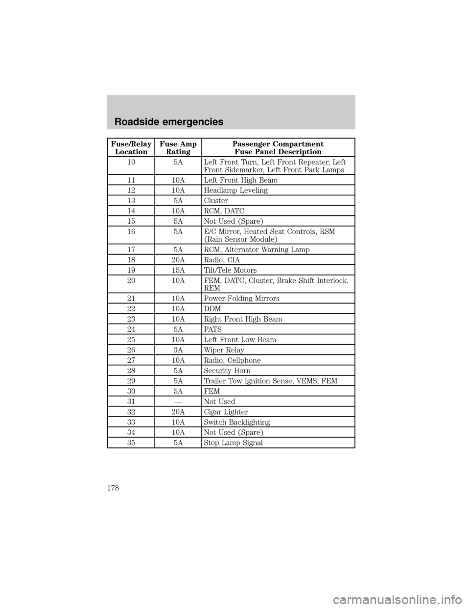
Fuse/Relay
LocationFuse Amp
RatingPassenger Compartment
Fuse Panel Description
10 5A Left Front Turn, Left Front Repeater, Left
Front Sidemarker, Left Front Park Lamps
11 10A Left Front High Beam
12 10A Headlamp Leveling
13 5A Cluster
14 10A RCM, DATC
15 5A Not Used (Spare)
16 5A E/C Mirror, Heated Seat Controls, RSM
(Rain Sensor Module)
17 5A RCM, Alternator Warning Lamp
18 20A Radio, CIA
19 15A Tilt/Tele Motors
20 10A FEM, DATC, Cluster, Brake Shift Interlock,
REM
21 10A Power Folding Mirrors
22 10A DDM
23 10A Right Front High Beam
24 5A PATS
25 10A Left Front Low Beam
26 3A Wiper Relay
27 10A Radio, Cellphone
28 5A Security Horn
29 5A Trailer Tow Ignition Sense, VEMS, FEM
30 5A FEM
31 Ð Not Used
32 20A Cigar Lighter
33 10A Switch Backlighting
34 10A Not Used (Spare)
35 5A Stop Lamp Signal
Roadside emergencies
178
Page 180 of 272

The high-current fuses are coded as follows.
Fuse/Relay
LocationFuse Amp
RatingPower Distribution Box Description
1 10A* A/C Clutch
2 10A* Windshield Washer Pump
3 15A* Fog Lamp
4 15A* Horn
5 20A* Fuel Injectors
6 15A* Transmission Solenoid
7 Ð Not Used
8 Ð Not Used
9 Ð Not Used
10 Ð Not Used
11 15A* HEGO's
12 10A* COP's
13 30A** Heated Wiper Park
RELAY
14RELAY
15
RELAY
11RELAY
12
RELAY
1013
1234
5678
9 10111214 15 16 17 18
19 20 21 22 23 24
RELAY
13RELAY 08DIODE
RELAY 04 RELAY 05RELAY 01
RELAY 09
RELAY 06
RELAY 02RELAY 07
RELAY 03
Roadside emergencies
180
Page 181 of 272

Fuse/Relay
LocationFuse Amp
RatingPower Distribution Box Description
14 30A** ABS Module
15 Ð Not Used
16 30A** Blower Motor
17 20A** Thermactor Air Pump (Low Emission
Vehicles Only)
18 40A** PCM
19 Ð Not Used
20 30A** Wiper Motor
21 30A** Starter Solenoid
22 30A** ABS Motor
23 Ð Not Used (Fuse Plug)
24 Ð Not Used
Relay 01 Ð Wiper Hi/Lo
Relay 02 Ð Wiper Park
Relay 03 Ð COP's and HEGO's
Relay 04 Ð Windshield Washer
Relay 05 Ð Auxiliary Coolant Pump (V8)
Relay 06 Ð Horn
Relay 07 Ð Fog Lamps
Relay 08 Ð A/C Clutch
Relay 09 Ð Wiper Run/Acc
Relay 10 Ð Blower Motor
Relay 11 Ð Not Used
Relay 12 Ð Heated Wiper Park
Relay 13 Ð Not Used
Relay 14 Ð PCM Power
Relay 15 Ð Starter Motor
Diode Ð PCM
*Mini fuses **Cartridge fuses
Roadside emergencies
181